Feedback
Table Of Contents
Cisco's Implementation of LAPB and X.25
Facility Handling in Encapsulated X.25 Virtual Circuits
Establish LAPB DCE or DTE Operation
Configure LAPB Timers and Frame Parameters
Define the LAPB Hold Queue Size
Configure an X.25 Datagram Transport
Set the X.121 Interface Address
Understand Single-Protocol and Multiprotocol Virtual Circuit Options
Map Datagram Addresses to X.25 Hosts
Establish a Permanent Virtual Circuit (PVC)
Establish a Default Virtual Circuit Protocol
Cisco's Implementation of DDN X.25 Dynamic Mapping
Configure Blacker Emergency Mode
Apply an Access List to a Line
Configure X.25 Level 3 Parameters and Special Features
Configure Virtual Circuit Ranges
Configure the Switched Virtual Circuit Idle Timer
Increase the Number of Virtual Circuits Allowed
Configure the Ignore Destination Timer
Set Default Maximum Packet Sizes
Establish the Packet Acknowledgment Policy
Configure the X.25 Level 3 Retransmission Timers
Set X.25 TCP Header Compression
Configure X.25 Packet-by-Packet Compression
Define the Default Encapsulation Protocol
Configure the X.25 User Facilities
Set the Packet Numbering Modulo
Define the Virtual Circuit Packet Hold Queue Size
Monitor and Maintain LAPB and X.25
LAPB and X.25 Configuration Examples
Typical LAPB Configuration Example
Typical X.25 Configuration Example
Virtual Circuit Ranges Example
DDN X.25 Configuration Example
Configuring LAPB and X.25
This chapter describes how to configure connections through X.25 networks, including Link Access Procedure Balanced (LAPB) connections. LAPB procedures are presented first for those users who only want to configure a simple, reliable serial encapsulation method. For a complete description of the commands mentioned in this chapter, refer to the "X.25 Configuration Commands" chapter in the Access and Communication Servers Command Reference publication.
Cisco's Implementation of LAPB and X.25
A group of specifications published by the ITU-T defines Recommendations, or specifications, for X.25.
Note
The ITU-T carries out the functions of the former Consultative Committee for International Telegraph and Telephone (CCITT).
The ITU-T specifications specify connections between data terminal equipment (DTE) and data communications equipment (DCE) for remote terminal access and computer communications. The X.25 specifications include LAPB as the data link layer protocol and X.25 as the network layer protocol, or packet layer protocol (PLP) as it is also known. The ITU-T updates its specifications every four years, and the specifications dated 1980 and 1984 are the most common versions currently in use.
Additionally, the International Organization for Standardization (ISO) has published ISO 7776:1986 as an equivalent to the LAPB standard, and ISO 8208:1989 as an equivalent to the ITU-T 1984 X.25 Recommendation packet layer. Our X.25 software follows the CCITT 1984 X.25 Recommendation, except for its Defense Data Network (DDN) and Blacker Front-End Encryption (BFE) encapsulation operation, which follows the CCITT 1980 X.25 Recommendation.
Briefly, our X.25 software provides the following capabilities:
•
•
•
•
•
Facility Handling in Encapsulated X.25 Virtual Circuits
The access server either originates or accepts encapsulation virtual circuits in order to transport LAN traffic through an X.25 network.
When the access server originates a CALL for LAN traffic encapsulation, the facilities in the CALL are controlled by the facilities configured for the interface and the map statement that specifies the LAN/X.25 encapsulation. Because an access server may be attached to a Public Data Network (PDN), the interface and map configurations allow a number of facilities to be specified in outgoing CALLs. These facilities are specified in all originated CALLs relating to the given interface and map with one exception; the incoming and outgoing maximum packet sizes proposed will be lowered if the lower layer (LAPB) cannot support the specified DATA packet size.
When the access server accepts an encapsulation CALL, many facilities are simply ignored. The maximum packet sizes will be lowered if the lower layer (LAPB) cannot support the sizes proposed. A reverse-charged CALL will be CLEARed if neither the interface nor the map allows it. A CALL that specifies a Network User Identification (NUID) will be CLEARed if the user authentication fails.
LAPB Configuration Task List
It is possible to use only LAPB as a serial encapsulation method. This can be done using a leased serial line. You must use one of the X.25 packet-level encapsulations when attaching to an X.25 network.
The LAPB standards distinguish between two types of hosts: data terminal equipment (DTE), and data circuit-terminating equipment (DCE). At Level 2, or the data link layer in the OSI model, LAPB allows for orderly and reliable exchange of data between a DTE and a DCE. An access server using LAPB encapsulation can act as a DTE or DCE device at the protocol level, which is distinct from the hardware DTE or DCE level.
Using LAPB under noisy conditions can result in greater throughput than HDLC encapsulation. When LAPB detects a missing frame, the access server retransmits the frame instead of waiting for the higher layers to recover the lost information. This behavior is good only if the host timers are relatively slow. In the case of quickly expiring host timers, however, you will discover that LAPB is spending much of its time transmitting host retransmissions. If the line is not noisy, the lower overhead of HDLC encapsulation is more efficient than LAPB. When using long delay satellite links, for example, the lock-step behavior of LAPB makes HDLC encapsulation the better choice.
Perform the following tasks to configure LAPB:
•
•
•
•
The following sections describe the LAPB configuration tasks. Refer to the section "Monitor and Maintain LAPB and X.25" later in this chapter for the LAPB administrative tasks. Examples of LAPB configurations appear at the end of this chapter.
Establish LAPB DCE or DTE Operation
Set the appropriate LAPB encapsulation to run datagrams over a serial interface. One end of the link must be DTE and the other must be DCE.
Select an encapsulation and the protocol if using a single protocol, or select the multiple protocol operation, according to the table that follows. Perform the following tasks in interface configuration mode:
For an example of configuring LAPB DCE operation, see the section "Typical LAPB Configuration Example" later in this chapter.
Configure LAPB Timers and Frame Parameters
X.25 Level 2 or LAPB operates at the data link layer of the OSI reference model. LAPB specifies methods for exchanging data (in units called frames), detecting out-of-sequence or missing frames, retransmitting frames, and acknowledging frames.
The LAPB modulo determines the operating mode. Modulo 8 (basic mode) is widely available, because it is required for all standard LAPB implementations and is sufficient for most links. Modulo 128 (extended mode) can achieve greater throughput on high-speed links that have a low error rate (satellite links, for example) by increasing the number of frames that can be transmitted before waiting for acknowledgment (as configured by the LAPB window parameter, k). By its design, LAPB's k parameter can be at most one less than the operating modulo. Modulo 8 links can typically send seven frames before an acknowledgment must be received; modulo 128 links can set k to a value as large as 127. By default, LAPB links use the basic mode with a window of 7.
When connecting to an X.25 network, use the N1 parameter value set by the network administrator. This value is the maximum number of bits in a LAPB frame, which determines the maximum size of an X.25 packet. When using LAPB over leased lines, the N1 parameter should be eight times the hardware maximum transmission unit (MTU) size plus any LAPB overhead. The other frame parameters are determined by the network configuration; see for the default values.
The retransmission timer determines how long a transmitted frame can remain unacknowledged before the router polls for an acknowledgment. For X.25 networks, the router retransmission timer setting should match that of the network.
The LAPB standards define a timer to detect unsignaled link failures (T4). The T4 timer is reset every time a frame is received from the partner on the link. If the T4 timer expires, a Receiver Ready frame with the Poll bit set is sent to the partner, which is required to respond. If the partner does not respond, the standard polling mechanism is used to determine whether the link is down. The period of T4 must be greater than the period of T1.
Another LAPB timer function allows brief hardware failures, while the protocol is up, without requiring a protocol reset. If a brief hardware outage occurs, the link will continue uninterrupted if the outage is cured before the specified hardware outage period expires.
For leased-line circuits, the retransmission timer setting is critical. The timer setting must be large enough to permit a maximum-sized frame to complete one round trip on the link. If the timer setting is too small, the router will poll before the acknowledgment frame can return, which may result in duplicated frames and severe protocol problems; the design of LAPB assumes that a frame has been lost if it is not acknowledged within period T1. If the timer setting is too large, the router waits longer than necessary before requesting an acknowledgment, which reduces bandwidth.
summarizes the LAPB parameters you can set in interface configuration mode.
Table 8-1 LAPB Parameters
For an example of configuring the LAPB T1 timer, see the section "Typical LAPB Configuration Example" later in this chapter.
Define the LAPB Hold Queue Size
To define the maximum number of packets to be held while LAPB is unable to send data, perform the following task in interface configuration mode:
X.25 Configuration Task List
To configure X.25, you can choose from the following tasks, depending upon the X.25 application or task required for your network:
•
•
•
•
Note that all X.25 applications except DDN and BFE X.25 operation and routing require that an encapsulation method and an X.121 address be set; see the sections "Set X.25 DTE or DCE Operation" and "Set the X.121 Interface Address" for the tasks to do so.
Default parameters have been provided for X.25 operation; however, you can change the settings to meet the needs of your X.25 network or as defined by your X.25 service supplier. We also provide special and custom configuration settings to further optimize your X.25 network. See the section "Configure X.25 Level 3 Parameters and Special Features" later in this chapter for more information.
The following sections describe how to implement the supported configuration types and special configuration tasks. Refer to the Access and Communication Servers Command Reference publication for information about the commands in the tasks. See the section "LAPB and X.25 Configuration Examples" at the end of this chapter for configuration examples.
Configure an X.25 Datagram Transport
X.25 support is most commonly configured as a transport for datagrams across an X.25 network. This is accomplished by first establishing a mapping between protocol addresses (for example, IP or DECnet) and the X.121 addresses of the X.25 network. When datagrams for a particular destination are routed for the first time, a virtual circuit is set up to the appropriate X.121 address. The Call User Data portion of the initial Call Request identifies the protocol of the datagrams being carried by a particular virtual circuit. If multiple protocols are in use, multiple virtual circuits will be opened.
illustrates two access servers sending data across an X.25 public data network (PDN).
Figure 8-1 Transporting LAN Protocols across an X.25 PDN
You must perform the following tasks to configure your access server as a transport for X.25 datagrams (note that these tasks are required by all X.25 applications except DDN and BFE X.25):
•
•
Perform the following tasks, as necessary, to complete the X.25 configuration for your network needs:
•
•
•
•
The following sections describe how to perform these configuration tasks. Configuring the X.25 parameters and special features, including TCP header compression, are described in the section "Configure X.25 Level 3 Parameters and Special Features" later in this chapter.
Set X.25 DTE or DCE Operation
An access Server using X.25 Level 3 encapsulation can act as a DTE or DCE protocol device. Default serial encapsulation is HDLC. Configure one of these encapsulation types, according to the needs of your X.25 service supplier. To do so, perform the following task in interface configuration mode:
Set X.25 DTE operation.
encapsulation x25
Set X.25 DCE operation.
encapsulation x25-dce
Typically, a public data network will require attachment as a DTE. (This is distinct from the hardware interface DTE and DCE assignments.)
For an example of configuring X.25 DTE operation, see the section "Typical X.25 Configuration Example" later in this chapter.
Set the X.121 Interface Address
Set the X.121 address of the network interface. The X.121 address is assigned by the X.25 network service provider. To set the X.121 address, perform the following task in interface configuration mode:
For an example of configuring the X.25 interface address, see the section "Typical X.25 Configuration Example" later in this chapter.
Understand Single-Protocol and Multiprotocol Virtual Circuit Options
This section describes X.25 single-protocol and multiprotocol encapsulation options and describes how protocols are identified under both options.
Protocol Encapsulation
We support encapsulation of several datagram protocols across X.25, using a standard method, when available, or a proprietary method, when necessary. These traditional methods assign a protocol to each virtual circuit. If more than one protocol is carried between the router and a given host, each active protocol will have at least one virtual circuit dedicated to carrying its datagrams.
We also support a newer standard, RFC 1356, which standardizes a method for encapsulating most datagram protocols over X.25. It also specifies how one virtual circuit can carry datagrams from more than one protocol.
A router can be configured to use any of the available encapsulation methods with a particular host.
Once an encapsulation virtual circuit is established using any method, sending and receiving a datagram is a simple process of fragmenting and reassembling the datagram into and from an X.25 complete packet sequence. An X.25 complete packet sequence is one or more X.25 data packets that have the More bit set in all but the last packet. A virtual circuit that can carry multiple protocols includes protocol identification data as well as the protocol data at the start of each complete packet sequence.
Protocol Identification
The primary difference between the available encapsulation methods is the specific value used to identify a protocol. When any of the methods establishes a virtual circuit for carrying a single protocol, the protocol is identified in the Call packet by using the Call User Data (CUD) field. When a virtual circuit is established to carry more than one protocol (only available using the RFC 1356 methodology), a specific value is also encoded in the Call User Data field in each datagram; every datagram exchanged over that virtual circuit has its protocol identified.
Table 8-2 summarizes the values used in the Call User Data field to identify protocols.
Table 8-2 Protocol Identification in the Call User Data Field
AppleTalk
0xD2
0x80 (5-byte SNAP encoding)
ISO CLNS
0x81
0x811
Compressed TCP
0xD8
0x00 (5-byte SNAP encoding)2
IP
0xCC
0xCC3
or
0x80 (5-byte SNAP encoding)Novell IPX
0xD3
0x80 (5-byte SNAP encoding)
1 The use of 0x81 for CLNS is compatible with ISO/IEC 8473-3:1994.
2 Compressed TCP traffic has two types of datagrams, so IETF encapsulation requires a multiprotocol virtual circuit.
3 The use of 0xCC for IP is backward compatible with RFC 877.
Once a multiprotocol virtual circuit has been established, datagrams on the virtual circuit have protocol identification data before the actual protocol data; the values used are the same used by RFC 1356 in the CUD field for an individual protocol.
Note
Map Datagram Addresses to X.25 Hosts
Encapsulation is a cooperative process between the router and another X.25 host. Since X.25 hosts are reached using an X.121 address (an X.121 address has between 0 and 15 decimal digits), the router must have a means to map a host's protocol address (or addresses) to its X.121 address.
Each encapsulating X.25 interface should be configured with the relevant datagram parameters. For example, an interface that encapsulates IP will typically have an IP address.
A router set up for DDN or BFE service uses a dynamic mapping technique to convert between IP and X.121 addresses. These techniques have been designed specifically for attachment to the DDN network and to Blacker encryption equipment. Their design, restrictions, and operation make them work well for these specific applications, but not for other networks.
You should also establish the X.121 address of an encapsulating X.25 interface using the x25 address interface configuration command. This is the address that encapsulation Calls should be directed to. It will also be used as the source X.121 address when originating an encapsulation Call, which is how the destination host will be able to determine what services are needed for the encapsulation virtual circuit. A DDN or BFE interface will have an X.121 address generated from the interface IP address, which for proper operation, should not be modified.
For each X.25 interface, you can explicitly map each destination host's protocols and addresses to its X.121 address. If needed and the destination host has the capability, one host map can be configured to support several protocols; alternatively, you can define one map for each supported protocol.
To establish a map, perform the following task in interface configuration mode:
Map one or more host protocol addresses to the host's X.121 address.
x25 map protocol1 address1 [protocol2 address2...protocol9 address9] x.121-address [option]
As an example, if you are encapsulating IP over a given X.25 interface, you should define an IP address for the interface and, for each of the desired destination hosts, map the host's IP address to its X.121 address.
Note
An individual host map can specify the following protocols using the given keyword:
•
•
•
A multiprotocol map can specify a single address for all of the protocols listed above (except bridging and QLLC, which are not supported for RFC 1356 encapsulation). If IP and TCP header compression are both specified, the same IP address must be given for both protocols.
When setting up the address map, you can include options, such as enabling broadcasts and specifying the number of virtual circuits allowed, and defining various user facility settings.
Note
For specific information about how to establish a protocol to run over X.25, refer to the appropriate protocol chapters in this publication.
The configuration for the Open Shortest Path First (OSPF) protocol can be greatly simplified by adding the optional broadcast keyword when doing this task. See the x25-map description in the Access and Communication Servers Command Reference publication for more information.
Establish a Permanent Virtual Circuit (PVC)
Permanent virtual circuits (PVCs) are the X.25 equivalent of leased lines; they are never disconnected. Specify the required network protocol-to-X.121 address map before you set up a PVC. To establish a PVC, perform the following task in interface configuration mode:
IP and Novell IPX are supported by this task.
Establish a Default Virtual Circuit Protocol
The Call Request packet that sets up a virtual circuit might contain a field called the Call User Data (CUD) field. Typically, the software uses the first byte of Call User Data to distinguish which high-level protocol will be carried by a particular virtual circuit.
lists the hexadecimal values of the initial byte of Call User Data and its corresponding network level protocol. The use of 0xCC for Department of Defense IP is defined by RFC 877. The other values are meaningful only to our X.25 software. Most of the single-byte identifiers are padded to four bytes with three bytes of 0x00. BFE IP encapsulation requires that only one byte be used. CLNS may use one or five bytes as defined in ISO 8473.
Table 8-3 Protocols and Initial Byte of Call User Data
You can specify the protocol assumed by the access server to interpret calls with unknown Call User Data (CUD) or with no CUD by performing the following task in interface configuration mode:
Configure DDN or BFE X.25
The DDN X.25 protocol has two versions: Basic Service and Standard Service. Our X.25 implementation only supports the Standard Service. DDN X.25 Standard Service requires that the X.25 data packets carry IP datagrams. The DDN Packet Switch Nodes (PSNs) can extract the IP packet from within the X.25 packet and pass data to another Standard Service host.
The DDN X.25 Standard is the required protocol for use with DDN PSNs. The Defense Communications Agency (DCA) has certified our DDN X.25 Standard implementation for attachment to the Defense Data Network. As part of the certification, our software is required to provide a scheme for dynamically mapping IP address to X.121 addresses. See the section "Cisco's Implementation of DDN X.25 Dynamic Mapping" that follows for details on that scheme.
Complete the following tasks to enable DDN X.25 service:
•
Perform the following task, as necessary, to complete the configuration.
•
Cisco's Implementation of DDN X.25 Dynamic Mapping
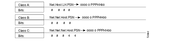
The DDN X.25 standard implementation includes a scheme for dynamically mapping all classes of IP addresses to X.121 addresses without a table. This scheme requires that the IP addresses conform to the formats shown in . These formats segment the IP addresses into network (N), host (H), logical address (L), and PSN (P) portions. (The acronym PSN stands for Packet Switch Node.) For the BFE encapsulation, the IP address is segmented into Port (P), Domain (D), and BFE ID number (B). The DDN algorithm requires that the host value be less than 64.
Figure 8-2 DDN Internet/X.121 Address Conventions
The DDN conversion scheme uses the host and PSN portions of an IP address to create the corresponding X.121 address. Strictly speaking, the DDN conversion mechanism is limited to Class A IP addresses. However, the access server can convert Class B and Class C addresses as well. As indicated, this method uses the last two octets of a Class B address as the host and PSN identifiers, and the upper and lower four bits in the last octet of a Class C address as the host and PSN identifiers, respectively. The BFE conversion scheme requires a Class A IP address.
The DDN conversion scheme uses a physical address mapping if the host identifier is numerically less than 64. (This limit derives from the fact that a PSN cannot support more than 64 nodes.) If the host identifier is numerically larger than 64, the resulting X.121 address is called a logical address. The DDN does not use logical addresses.
The format of physical DDN X.25/X.121 addresses is ZZZZFIIIHHZZ(SS), where each character represents a digit. ZZZZ represents four zeros, F is zero to indicate a physical address, III represents the PSN octet from the IP address padded with leading zeros, HH is the host octet from the IP address padded with leading zeros, and ZZ represents two zeros. (SS) represents the optional and unused subaddress.
The physical and logical mappings of the DDN conversion scheme always generate a 12-digit X.121 address. Subaddresses are optional; when added to this scheme, the result is a 14-digit X.121 address. The DDN does not use subaddressing.
Packets using routing and other protocols that require broadcast support can successfully traverse X.25 networks, including the DDN. This traversal requires the use of network protocol-to-X.121 maps, because the access server must know explicitly where to deliver broadcast datagrams. (X.25 does not support broadcasts.) You can mark network protocol-to-X.121 map entries to accept broadcast packets; the access server then sends broadcast packets to hosts with marked entries. If you do not specify the address for an interface configured for DDN X.25, the access server uses the DDN mapping technique to obtain the X.121 address of an interface.
Enable DDN X.25
Both DCE and DTE operation cause the access server to specify the Standard Service facility in the Call Request packet, which notifies the PSNs to use Standard Service.
Perform one of the following tasks in interface configuration mode, as appropriate for your network:
Set DDN X.25 DTE operation.
encapsulation ddnx25
Set DDN X.25 DCE operation.
encapsulation ddnx25-dce
For an example of enabling DDN X.25, see the section "DDN X.25 Configuration Example" later in this chapter.
Define IP Precedence Handling
Using Standard Service, the DDN can be configured to provide efficient service for datagrams with Index high precedence values. If the access server receives an IP packet with a nonzero protocol precedence field, it uses a different virtual circuit and sets the precedence facility request to the DDN-specified precedence mapping in the Call Request packet. Different virtual circuits are maintained based on the precedence mapping values and the number of virtual circuits permitted.
By default, the DDN X.25 software opens one virtual circuit for all types of service values. You can enable the precedence sensitivity feature by performing the following task in interface configuration mode:
Allow a new virtual circuit based on the type of service (TOS) field.
x25 ip-precedence
Some hosts send nonstandard data in the TOS field, thereby causing multiple, wasteful virtual circuits to be created.
Configure Blacker Emergency Mode
For environments that require a high level of security, your access server software supports the Defense Data Network Blacker Front-End Encryption (BFE) and Blacker Emergency Mode.
Blacker Emergency Mode allows your BFE device and your access server to function in emergency situations. When the access server is configured to participate in emergency mode and the BFE device is in emergency mode, the access server sends address translation information to the BFE device to assist it in sending information.
Our implementation of Blacker Emergency Mode adheres to the specifications outlined in the DCA Blacker Interface Control document, published March 21, 1989.
Your BFE device is configured to be in one of three possible modes as follows:
•
•
•
Perform these tasks to configure Blacker Emergency Mode:
•
•
•
•
The following tables describe these tasks.
BFE encapsulation operates to map between Class A IP addresses and the X.121 addresses expected by the BFE encryption device. To set BFE encapsulation, perform the following task in interface configuration mode:
Set BFE encapsulation on the access server attached to a BFE device.
encapsulation bfex25
For an example of enabling Blacker Emergency mode, see the section "BFE Emergency Mode Example" later in this chapter.
You must set up a table that provides the address translation information the access server sends to the BFE when the BFE is in emergency mode. To do so, perform the following task in interface configuration mode
Set up the table that lists the BFE nodes (host or gateways) to which the access server will send packets.
x25 remote-red host-ip-address remote-black
blacker-ip-address
:
For an example of configuring setting up the table, see the section "BFE Emergency Mode Example" later in this chapter.
You can define the circumstances under which the access server participates in emergency mode and how it will participate in emergency mode. To do so, perform the following tasks in interface configuration mode:
For an example of configuring the circumstances under which the access server participates in emergency mode, see the section "BFE Emergency Mode Example" later in this chapter.
To set the access server to participate in emergency mode or to end participation in emergency mode when your system is so configured, perform the following task in EXEC mode:
For an example of configuring the access server to participate in emergency mode, see the section "BFE Emergency Mode Example" later in this chapter. See the previous task for more information about configuring the access server to participate in emergency mode.
Create X.29 Access Lists
Protocol translation software supports access lists, which make it possible to limit access to the access server from X.25 hosts. Access lists take advantage of the message field defined by Recommendation X.29, which describes procedures for exchanging data between two PADs or between a PAD and a DTE device.
To define X.29 access lists, perform the following tasks:
Step 1
Step 2
These tasks are described in the following sections.
When configuring protocol translation, you can specify an access list number with each translate command. When translation sessions result from incoming PAD connections, the corresponding X.29 access list is used. Refer to the chapter "Protocol Translation Configuration Commands" in the Access and Communication Servers Command Reference publication for more information about the translate command.
Create an Access List
To specify the access conditions, perform the following global configuration task:
An access list can contain any number of lines. The lists are processed in the order in which you type the entries. The first match causes the permit or deny condition. If an X.121 address does not match any of the entries in the access list, access will be denied.
Apply an Access List to a Line
To apply an access list to a virtual line, perform the following task in line configuration mode:
Restrict incoming and outgoing connections between a particular virtual terminal line (into a Cisco device) and the addresses in an
access list.access-class access-list-number in
The access list number is used for incoming TCP access, incoming LAT access, and for incoming PAD access. For TCP access, the protocol translator uses the defined IP access lists. For LAT access, the protocol translator uses the defined LAT access list. For incoming PAD connections, an X.29 access list is used. If you want to have access restrictions only on one of the protocols, then you can create an access list that permits all addresses for the other protocol.
For information about applying an access list using the translate command, refer to the chapter "Protocol Translation Configuration Commands" in the Access and Communication Servers Command Reference publication.
Create an X.29 Profile Script
You can create an X.29 profile script for use by the translate command. When an X.25 connection is established, the protocol translator then acts as if an X.29 SET PARAMETER packet had been sent that contained the parameters and values set by this command.
To create an X.29 profile script, perform the following global configuration task:
Configure X.25 Level 3 Parameters and Special Features
The Cisco IOS software allows you to configure the standard Level 2 and Level 3 X.25 parameters and user facilities.
Note
This section describes the X.25 parameters, user facilities, and special features you can configure. Which tasks you perform depends upon the structure of your network and the requirements of the service provider. These parameters must be adjusted to match the values used by the X.25 network. It is common for networks to require values different from the our defaults.
Perform the following tasks to configure the optional parameters, user facilities, and special features:
•
•
•
•
•
•
•
•
•
•
•
•
•
•
The following sections describe these tasks.
Configure Virtual Circuit Ranges
The X.25 protocol maintains multiple connections over one physical link between a DTE and a DCE. These connections are called virtual circuits or logical channels. X.25 can maintain up to 4095 virtual circuits numbered 1 through 4095. An individual virtual circuit is identified by giving its logical channel identifier or virtual circuit number. Many documents use the following terms interchangeably: virtual circuit and logical channel. The same is true for the terms virtual circuit number, logical channel number, and logical channel identifier.
An important part of X.25 operation is the range of virtual circuit numbers. Virtual circuit numbers are broken into four ranges (listed here in numerically increasing order):
1
2
3
4
The incoming-only, two-way, and outgoing-only ranges define the virtual circuit numbers over which a switched virtual circuit (SVC) can be established by placing an X.25 call, much like a telephone network establishes a switched voice circuit when a call is placed.
The rules about DCE and DTE devices initiating calls are as follows:
•
•
•
There is no difference in the operation of the SVCs except the restrictions on which a device can initiate a call. These ranges can be used to prevent one side from monopolizing the virtual circuits, which can be useful for X.25 interfaces with a small total number of SVCs available.
Six X.25 parameters define the upper and lower limit of each of the three SVC ranges. A permanent virtual circuit (PVC) must be assigned a number less than the numbers assigned to the SVC ranges. An SVC range is not allowed to overlap another range.
For a list of virtual circuit range types and the corresponding commands used to configure the ranges, refer to the "X.25 Configuration Commands" chapter in the Access and Communication Servers Command Reference publication.
Note
To set the X.25 virtual circuit parameters, perform any of the following tasks in interface configuration mode:
For an example of configuring virtual circuit ranges, see the section "Virtual Circuit Ranges Example" later in this chapter.
Configure the Switched Virtual Circuit Idle Timer
The access server can clear datagram transport switched virtual circuit (SVC) after a set period of inactivity. You can set this time by performing the following task in interface configuration mode:
For an example of configuring the SVC idle timer, see the section "Typical X.25 Configuration Example" later in this chapter. See the section "Monitor and Maintain LAPB and X.25" later in this chapter for additional commands that clear virtual circuits.
Increase the Number of Virtual Circuits Allowed
You can establish up to eight switched virtual circuits to a host for each protocol used in X.25 datagram transport. Perform one or both of the following tasks to increase the number of virtual circuits allowed:
For an example of increasing the number of virtual circuits allowed, see the sections "Typical X.25 Configuration Example" and "DDN X.25 Configuration Example" later in this chapter.
Configure the Ignore Destination Timer
Upon receiving a Clear for an outstanding datagram transport Call Request, the X.25 support code immediately tries another Call Request if it has more traffic to send. This action can overrun some X.25 switches. You can define the number of minutes it takes to prevent calls from going to a previously failed destination by performing the following task in interface configuration mode:
Incoming calls will still be accepted.
Set Default Window Sizes
X.25 networks have a default input and output window size that is defined by the network administrator. You must set the access server default input and output window sizes to match those of the network; see the note following the next section "Set Default Maximum Packet Sizes."
To set the default window sizes, perform the following tasks in interface configuration mode:
For an example of setting the default window sizes, see the sections "Typical X.25 Configuration Example" and "DDN X.25 Configuration Example" later in this chapter.
Set Default Maximum Packet Sizes
X.25 networks have a default maximum input and output packet size that is defined by the network administrator. You must set the access server default input and output maximum packet sizes to match those of the network by performing the following tasks in interface configuration mode:
Set the default input maximum packet size.
128
x25 ips bytes
Set the default output maximum packet size.
128
x25 ops bytes
To send a packet larger than the agreed X.25 packet size over an X.25 virtual circuit, an access server must break the packet into two or more X.25 packets with the M-bit ("more data" bit) set. The receiving device collects all packets in the M-bit sequence and reassembles them.
For an example of setting the default maximum packet sizes, see the sections "Typical X.25 Configuration Example" and "DDN X.25 Configuration Example" later in this chapter.
Note
Establish the Packet Acknowledgment Policy
You can instruct the access server to send an acknowledgment packet when it has received a threshold of data packets it has not acknowledged, instead of waiting until its input window is full. A value of 1 will send an acknowledgment for each data packet received if it cannot be acknowledged in an outgoing data packet. A value of 0 restores the default behavior of waiting until the input window is full. This approach improves line responsiveness at the expense of bandwidth. To do so, perform the following task in interface configuration mode:
Configure the X.25 Level 3 Retransmission Timers
The X.25 Level 3 retransmission timers determine how long the access server must wait before retransmitting various packets (an expiring call timer causes the virtual circuit to be cleared). You can set these timers independently using the commands listed in the "X.25 Configuration Commands" chapter in the Access and Communication Servers Command Reference publication. Each keyword requires a time value in seconds as its argument. The last column shows the default timer values, in seconds. Four of the timers apply to DTE devices, and the other four apply to DCE devices. To set the retransmission timers, perform any of the following tasks in interface configuration mode:
For an example of setting the default packet sizes, see the section "DDN X.25 Configuration Example" later in this chapter.
Set X.25 TCP Header Compression
You can configure two types of compression for X.25 interfaces:
•
•
We support RFC 1144 TCP/IP header compression on serial lines using HDLC and X.25 encapsulation. The implementation of Compressed TCP over X.25 uses one virtual circuit to pass the compressed packets. Any noncompressed packets are carried over separate IP encapsulations. To set X.25 TCP header compression perform the following tasks interface configuration mode:
To allow a separate virtual circuit for compressed packets.
x25 map compressedtcp ip-address x.121-address [options]
Configure X.25 Packet-by-Packet Compression
For increased efficiency on relatively slow networks, our access servers support packet-by-packet compression of outgoing calls over X.25.
Several restrictions apply to packet-by-packet compression:
•
•
•
•
•
To enable packet-by-packet compression over X.25, perform the following task in interface configuration mode:
Enable packet-by-packet compression over X.25.
x25 map protocol address [protocol address] x.121-address compress
This command specifies that X.25 compression is to be used when mapping outgoing traffic to the specified host. Because each virtual circuit established for compressed traffic uses significant amounts of memory, compression should be used with careful consideration of its impact on the router's performance.
Define the Default Encapsulation Protocol
To instruct the access server how to interpret unknown Call User Data, perform the following task in interface configuration mode:
Configure the X.25 User Facilities
The X.25 software provides commands to support X.25 user facilities—options specified by the creators of the X.25 Recommendation—that allow you to implement features such as accounting, user identification, and flow control negotiation. The facilities configured by the x25 map commands are on a per-peer basis; the x25 facility commands specify the values sent for calls originated by the interface. Routed calls are not affected by the facilities specified for the outgoing interface.
To set the supported X.25 user facilities, perform one or more of the following tasks in interface configuration mode:
Additionally, the D-bit is supported and passed through transparently. Both restricted and unrestricted fast select are also supported and are transparently handled by the software. No configuration is required for use of the D-bit or fast select facilities.
Set the Packet Numbering Modulo
The Cisco implementation of X.25 supports the extended packet sequence numbering. To use the extended packet sequence, perform the following task in interface configuration mode:
Note
Suppress the Calling Address
You can omit the calling (source) address in outgoing calls. This option is required for networks that expect only subaddresses in the calling address field. To suppress the calling address, perform the following task in interface configuration mode:
Omit the calling (source) X.121 address in Call Request packets.
x25 suppress-calling-address
Suppress the Called Address
You can omit the called (destination) address in outgoing calls. This option is required for networks that expect only subaddresses in the called address field. To suppress the called address, perform the following task in interface configuration mode:
Omit the called (destination) X.121 address in Call Request packets.
x25 suppress-called-address
Disable Packet-Level Restarts
By default, a packet-level Restart is performed when the link level is reset. This behavior can be disabled for networks that do not allow it, but disabling this behavior can cause anomalous packet layer behavior. To disable packet-level restarts, perform the following task in interface configuration mode:
Define the Virtual Circuit Packet Hold Queue Size
You can define the maximum number of packets that can be held while a virtual circuit is unable to send data. To define the size of the packet hold queue, perform the following task in interface configuration mode:
Monitor and Maintain LAPB and X.25
To monitor and maintain X.25 and LAPB, perform any of the following tasks in EXEC mode:
Note
LAPB and X.25 Configuration Examples
Use the examples in this section to help you understand how to configure LAPB and X.25 for your network. The examples provided are as follows:
•
•
•
•
Typical LAPB Configuration Example
In the following example, the frame size (N1), window size (k), and maximum retransmission (N2) parameters retain their default values. The encapsulation command sets DCE operation for IP packets only, and the lapb t1 command sets the retransmission timer to 4,000 milliseconds (4 seconds) for a link with a long delay or slow connecting DTE device.
interface serial 0encapsulation lapb-dcelapb t1 4000Typical X.25 Configuration Example
The following example shows the complete configuration for a serial interface connected to a commercial X.25 PDN for routing the IP protocol. The IP subnetwork address 131.108.9.0 has been assigned for the X.25 network.
Note
interface serial 0ip address 172.30.9.1 255.255.255.0!encapsulation X25!! The "bandwidth" command is not part of the X.25! configuration; it's especially important to understand that it doesn't! have any connection with the X.25 entity of the same name.!"bandwidth" commands are used by IP routing processes (currently only IGRP),! to determine which lines are the best choices for traffic.! Because the default is 1544, and X.25 service at that rate isn't generally! available, most X.25 interfaces that are being used with IGRP in a! real environment will have "bandwidth" settings.!! This is a 9.6 Kbaud line:!bandwidth 10!! These Level 3 parameters are default flow control values; they need to! match the PDN defaults. The values used by an SVC are negotiable on a per-call basis:!x25 win 7x25 wout 7x25 ips 512x25 ops 512!! You must specify the X.121 address to be assigned to the X.25 ! interface by the PDN.!x25 address 31370054065!! The following Level 3 parameters have been set to match the network.! You generally need to change some Level 3 parameters, most often! those listed below. You may not need to change any Level 2! parameters, however.!x25 htc 32x25 idle 5x25 nvc 2!! The following commands configure the X.25 map. If you want to exchange! routing updates with any of the access servers, they would need ! "broadcast" flags.! If the X.25 network is the only path to them, static routes are! generally used to save on packet charges. If there is a redundant ! path, it might be desirable to run a dynamic routing protocol.!x25 map IP 172.30.9.3 31370019134 ACCEPT-REVERSE! (ACCEPT-REVERSE allows collect calls)x25 map IP 131.108.9.2 31370053087!! If the PDN cannot handle fast back-to-back frames, use the!"transmitter-delay" command to slow down the interface:!transmitter-delay 1000Virtual Circuit Ranges Example
The following example sets the following virtual circuit ranges: 5 to 20 dedicated to incoming calls only (from the DCE to the DTE), 25 to 1024 for either incoming or outgoing calls, no virtual circuit range dedicated to outgoing calls (from the DTE to the DCE). Up to four permanent virtual circuits can be defined on virtual circuits 1 through 4.
x25 lic 5x25 hic 20x25 ltc 25DDN X.25 Configuration Example
The following example illustrates how to configure an access server interface to run DDN X.25:
interface serial 0ip address 172.30.7.50 255.255.255.240encapsulation DDNX25x25 win 6x25 wout 6x25 ips 1024x25 ops 1024x25 t20 10x25 t21 10x25 t22 10x25 t23 10x25 nvc 2x25 map IP 172.30.7.49 000000010300 BROADCASTBFE Emergency Mode Example
In the following example, serial interface 0 is configured to require an EXEC command from the administrator before it participates in emergency mode. The host IP address is 172.30.0.12, and the address of the remote BFE unit is 172.30.0.1. When the BFE enters emergency mode, the access server will prompt the administrator for EXEC command bfe enter to direct the access server to participate in emergency mode.
interface serial 0ip address 172.30.0.2 255.0.0.0encapsulation bfex25x25 bfe-emergency decisionx25 remote-red 172.30.0.12 remote-black 172.30.0.1x25 bfe-decision askNetboot over X.25 Example
When netbooting over X.25, you cannot netboot via a broadcast. You must netboot from a specific host. Also, an x25 map command must exist for the host that you netboot from. The x25 map command is used to map an IP address into an X.121 address. There must be an x25 map command that matches the IP address given on the boot system command line. The following is an example of such a configuration:
boot system gs3-bfx.83-2.0 172.30.13.111!interface Serial 1ip address 172.30.126.200 255.255.255.0encapsulation X25x25 address 10004x25 map IP 172.30.13.111 10002 broadcastlapb n1 12040clockrate 56000In this case, 10002 is the X.121 address of the remote access server that can get to host 172.30.13.111.
The remote access server must have the following x25 map entry:
x25 map IP 172.30.126.200 10004 broadcastThis entry allows the remote access server to return a boot image (from the netboot host) to the access server netbooting over X.25.
X.29 Access List Example
The following example illustrates an X.29 access lists. Incoming permit conditions are set for all IP hosts and LAT nodes that have specific characters in their names. All X.25 connections to a printer are denied. Outgoing connections are list restricted.
!Permit all IP hosts and LAT nodes beginning with "VMS".!Deny X.25 connections to the printer on line 5.!access-list 1 permit 0.0.0.0 255.255.255.255lat access-list 1 permit ^VMS.*x29 access-list 1 deny .*!line vty 5access-class 1 in!!Permit outgoing connections for other lines.!!Permit IP access with the network 131.108access-list 2 permit 172.30.0.0 0.0.255.255!!Permit LAT access to the boojum/snark complexes.lat access-list 2 permit ^boojum$lat access-list 2 permit ^snark$!!Permit X.25 connections to Infonet hosts only.x29 access-list 2 permit ^31370!line vty 0 16access-class 2 outX.3 Profile Example
The following profile script turns local edit mode on when the connection is made and establishes local echo and line termination upon receipt of a Return. The name "linemode" is used with the translate command to effect use of this script.
x29 profile linemode 2:1 3:2 15:1translate tcp 172.30.1.26 x25 55551234 profile linemodeThe X.3 PAD parameters are described in the "Configuring Protocol Translation" chapter in this publication.