Feedback
Table Of Contents
Interface Configuration Task List
Understand Supported Interfaces and Encapsulations
Synchronous Serial Compression
Synchronous Serial Encapsulation Methods
Asynchronous Serial Encapsulation Methods
Ethernet Encapsulation Methods
Token Ring Encapsulation Methods
Configure an Asynchronous Serial Interface
Configure an Ethernet Interface
Configure a Loopback Interface
Configure a Synchronous Serial Interface
Configure a Token Ring Interface
Configure Low-Speed Serial Interfaces on Cisco 2500 Routers
Overview of Half-Duplex DTE and DCE State Machines
Half-Duplex DTE State Machines
Half-Duplex DCE State Machines
Change between Controlled-Carrier and Constant-Carrier Modes
Place a Low-Speed Serial Interface in Controlled-Carrier Mode
Place a Low-Speed Serial Interface in Constant-Carrier Mode
Change between Controlled-Carrier and Constant-Carrier Modes Example
Tune Half-Duplex Timers Example
Change between Synchronous and Asynchronous Modes
Return a Low-Speed Serial Interface to Synchronous Mode
Specify the Mode of a Low-Speed Serial Interface Example
Configure Compression of PPP Data
Add a Description for an Interface
Configure Group and Member Asynchronous Interfaces
Define Slave Asynchronous Interface Characteristics
Configure the Tunnel Interface
Configure the Tunnel Destination
Configure End-to-End Checksumming
Configure a Tunnel Identification Key
Configure a Tunnel Interface to Drop Out-of-Order Datagrams
Understand Asynchronous Host Mobility
Configure Synchronous Serial Features
Reenable HDLC Serial Encapsulation
Configure Compression of HDLC Data
Configure Compression of LAPB Data
Configure the Clock Rate on DCE Appliques
Monitor and Maintain Snapshot Routing
Assigning IP Addresses to an Incoming Connection
Configure DHCP Address Pooling
Turn off DHCP Address Pooling on an Interface
Configure Local IP Address Pooling
Turn off Local IP Address Pooling on an Interface
Configure Specific IP Addresses for an Interface
Configure IP Address Pooling on Point-to-Point Links
Choose the IP Address Assignment Method
Define the Global Default Mechanism
Define DHCP as the Global Default Mechanism
Define Local Address Pooling as the Global Default Mechanism
Configure Per-Interface IP Address Assignment
Select the Ethernet Encapsulation
Configure the Point-to-Point Protocol
Enable CHAP or PAP Authentication
Enable Link Quality Monitoring
Ignore DCD and Monitor DSR as Line Up/Down Indicator
Control Interface Hold-Queue Limits
Limit Size of the Transmit Queue
Adjust Maximum Packet Size or MTU Size
Monitor and Maintain the Interface
Shut Down and Restart an Interface
Run Interface Loopback Diagnostics
Enable Loopback on MCI and SCI Serial Cards
Enable Loopback on MCI and MEC Ethernet Cards
Configure the Ethernet Loopback Server
Enable Loopback on Token Ring Cards
Interface Configuration Examples
Enabling Interface Configuration Example
Restricted Access on the Asynchronous Interface Example
SLIP and PPP Connection Examples
Interface Description Examples
Group and Member Asynchronous Interfaces Examples
CHAP with an Encrypted Password Example
When the Primary Line Goes Down
When the Primary Line Reaches Threshold
When the Primary Line Exceeds Threshold
Configure DHCP Pooling Examples
Configure Local Pooling Example
Configure Specific IP Addresses for an Interface Example
Configuring Interfaces
Use the information in this chapter to understand the types of interfaces supported on Cisco Systems access servers. Our access servers support two types of interfaces: physical and virtual interfaces.The virtual interfaces our access servers support include subinterfaces and IP tunnels.
For hardware technical descriptions and information about installing the access server interfaces, refer to the hardware installation and maintenance publication for your particular product. For command descriptions and usage information, refer to the Access and Communication Servers Command Reference publication.
Note
One or more of the commands that previously appeared in this chapter have been replaced by new commands. See the Access and Communication Servers Command Reference publication for command information. The old commands continue to perform their normal function in the current release, but support for them will cease in a future release.
Interface Configuration Task List
You can perform the tasks in the following sections to configure and maintain the interfaces supported on your access servers. The first section introduces material that you might need to know in advance of the other tasks.
•
•
•
•
•
•
•
•
•
•
•
•
•
•
•
See "Interface Configuration Examples" at the end of this chapter for interface configuration examples.
Understand Supported Interfaces and Encapsulations
The following sections describe the interfaces and encapsulations supported by our access servers.
Synchronous Serial
Support for the synchronous serial interface is supplied on the following serial network interface cards or systems:
•
•
•
The MCI and SCI cards can query the appliques to determine their types for use in reports displayed by the EXEC show commands. However, they do so only at system startup, so the appliques must be attached when the system is started. Use the show interfaces and show controllers mci EXEC commands to display the serial port numbers. These commands provide a report for each interface supported by the access server.
Synchronous Serial Compression
The synchronous serial interface supports point-to-point compression. Our software implements a predictor compressor (the RAND algorithm). Compression of LAPB data is supported for LAPB.
Synchronous Serial Encapsulation Methods
By default, synchronous serial lines use the High-level Data Link Control (HDLC) serial encapsulation method, which provides the synchronous framing and error detection functions of HDLC without windowing or retransmission. The synchronous serial interfaces support the following serial encapsulation methods:
•
•
•
•
•
Encapsulation methods are set according to the type of protocol or application you configure on your access server. HDLC is described later in this chapter in the section "Reenable HDLC Serial Encapsulation." PPP is described later in this chapter in the section "Configure the Point-to-Point Protocol." The remaining methods are described in their respective chapters describing the protocols or applications. Serial encapsulation methods are also discussed in the Access and Communication Servers Command Reference publication, under the encapsulation command.
Asynchronous Serial
Access and communication server platforms provide a number of methods to connect serial devices, including RJ-11, RJ-45, and 50-pin Telco connectors. The ASM-CS supports Telco and RJ-11 connectors. The Cisco 2500 series access servers support RJ-45 connectors on "octopus" cable adapters that attach to high-density D-type connectors on the rear panel of the servers.
Asynchronous Serial Encapsulation Methods
There are two asynchronous serial encapsulation methods:
•
•
Refer to the chapter "Configuring SLIP and PPP" later in this publication, for more information about these encapsulation methods.
Ethernet
Support for the Ethernet interface is supplied on one of the following Ethernet network interface cards or systems:
•
•
Use the show interfaces and show controllers mci EXEC commands to display the Ethernet port numbers. These commands provide a report for each interface supported by the access server.
Ethernet Encapsulation Methods
Currently, there are three common Ethernet encapsulation methods:
•
•
•
The encapsulation method you use depends upon the type of Ethernet media connected to the access server and the routing application you configure. Further detail is provided in the sections "Select the Ethernet Encapsulation" later in this chapter. See also the chapters describing the protocols or applications.
Token Ring
Support for the Token Ring interface is supplied on The 4/16-Mbps Token Ring cards, which interconnect network servers to IEEE 802.5 and IBM-compatible Token Ring media at speeds of 4 or 16 Mbps. These include the 4/16-Mbps cards or CSC-R16M, CSC-1R, and CSC-2R (dual Token Ring card).
Support for the Token Ring MIB variables is provided as described in RFC 1231, "IEEE 802.5 Token Ring MIB," by K. McCloghrie, R. Fox, and E. Decker, May 1991. The mandatory Interface Table and Statistics Table are implemented, but the optional Timer Table of the Token Ring MIB is not. The Token Ring MIB has been implemented for the TRIP.
Use the show interfaces and show controllers token EXEC commands to display the Token Ring numbers. These commands provide a report for each ring supported by the access server.
Note
Token Ring Encapsulation Methods
The Token Ring interface by default uses the SNAP encapsulation format defined in RFC 1042. It is not necessary to define an encapsulation method for this interface.
Configure the Interface Type
Begin interface configuration in global configuration mode. To configure an interface, follow these steps:
Step 1
Step 2
Serial 0 is administratively down, line protocol is downHardware is MCI SerialMTU 1500 bytes, BW 1544 Kbit, DLY 20000 usec, rely 255/255, load 1/255Encapsulation HDLC, loopback not set, keepalive set (10 sec)Use the show hardware EXEC command to see a list of the system software and hardware.
For example, to begin configuring interface Serial 0, you would add the following line to the configuration file:
interface serial 0
Note
Step 3
Step 4
The following sections show how to begin to configure each interface type as a separate task. Follow this command with the routing or bridging interface configuration commands for your particular protocol or application, as described in subsequent chapters.
See the section "Interface Configuration Examples" at the end of this chapter.
Configure an Asynchronous Serial Interface
To specify an asynchronous interface, perform the following task in global configuration mode.
For more information on asynchronous interfaces, refer to the chapter "Configuring SLIP and PPP" later in this publication. To use SLIP or PPP to make a connection, see the Cisco Access Connection Guide.
Configure a Dialer Interface
To specify a dialer rotary group leader, perform the following task in global configuration mode:
Configure an Ethernet Interface
To configure an Ethernet interface, perform the following task in global configuration mode:
Configure a Loopback Interface
You can specify a software-only interface called a loopback interface that emulates an interface that is always up. A loopback interface is a virtual interface that allows BGP and RSRB sessions to stay up even if the outbound interface is down, and is supported on all platforms.
You can use the loopback interface as the termination address for BGP sessions, for RSRB connections, or for establishing a Telnet session from the access server's console to its auxiliary port when all other interfaces are down. In applications where other access servers will attempt to reach this loopback interface, you need to configure a routing protocol to distribute the subnet assigned to the loopback address.
Packets routed to the loopback interface are rerouted back to the box and processed locally. IP packets routed out the loopback interface but not destined to the loopback interface are dropped. This means the loopback interface also serves as the Null 0 interface.
To configure a loopback interface, perform the following task in global configuration mode:
See also the section "Run Interface Loopback Diagnostics" later in this chapter.
Configure a Null Interface
The access server supports a "null" interface. This pseudo-interface functions similarly to the null devices available on most operating systems. This interface is always up and can never forward or receive traffic; encapsulation always fails. The only interface configuration command that you can specify for the null interface is no ip redirects.
The null interface provides an alternative method of filtering traffic. The overhead involved with using access lists can be avoided by directing undesired network traffic to the null interface.
To specify the null interface, perform the following task in global configuration mode:
Specify null 0 (or null0) as the interface name and unit. The null interface can be used in any command that has an interface type as an argument. The following example configures a null interface for IP route 172.16.0.0:
ip route 172.16.0.0 255.0.0.0 null 0Configure a Synchronous Serial Interface
To configure a synchronous serial interface, perform the following task in global configuration mode:
For synchronous serial features, see the section "Configure Synchronous Serial Features" later in this chapter.
Configure a Token Ring Interface
To configure a Token Ring interface, perform the following task in global configuration mode:
Configure Low-Speed Serial Interfaces on Cisco 2500 Routers
This section describes how to configure low-speed serial interfaces on Cisco 2520 through Cisco 2523 routers. It describes these tasks in the following sections:
•
•
•
•
Overview of Half-Duplex DTE and DCE State Machines
The following section describes the communication process between half-duplex DTE transmit and receive state machines and half-duplex DCE transmit and receive state machines.
Half-Duplex DTE State Machines
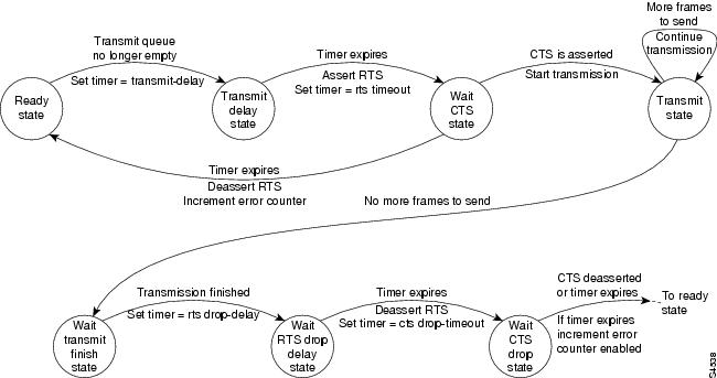
As shown in , the half-duplex DTE transmit state machine for low-speed interfaces remains in the ready state when it is quiescent. When a frame is available for transmission, the state machine transitions to the transmit delay state and waits for a time period, which is defined by the half-duplex timer transmit-delay value command. You can choose a value between the range of 0 to 4400 ms (4.4 seconds) to configure this command. The default is 0 ms. Transmission delays are used for debugging half-duplex links and assisting lower speed receivers that cannot process back-to-back frames.
Figure 1 Half-Duplex DTE Transmit State Machine
After idling for a defined number of ms, the state machine asserts request to send (RTS) and transitions to the wait clear to send (CTS) state for the data communications equipment (DCE) to assert CTS. A timeout timer with a value set by the half-duplex timer rts-timeout value command starts. The range you configure is dependent on the serial interface hardware that is installed. This default is 3 ms. If the timeout timer expires before CTS is asserted, the state machine returns to the ready state and de-asserts RTS. If CTS is asserted prior to the timer's expiration, the state machine transitions to the transmit state and sends the frames.
Once there are no more frames to transmit, the state machine transitions to the wait transmit finish state. The machine waits for the transmit first in first out (FIFO) in the serial controller to empty, starts a delay timer with a value defined by the half-duplex timer rts-drop-delay value interface command, and transitions to the wait RTS drop delay state. You can choose a value between the range of 0 and 1140000 ms (1140 seconds). The default is 3 ms.
When the timer in the wait RTS drop delay state expires, the state machine de-asserts RTS and transitions to the wait CTS drop state. A timeout timer with a value set by the half-duplex timer cts-drop-timeout value interface command starts, and the state machine waits for the CTS to de-assert. You can choose a value between the range of 0 to 1140000 ms (1140 seconds). The default is 250 ms. Once the CTS signal is de-asserted or the timeout timer expires, the state machine transitions back to the ready state. If the timer expires before CTS is de-asserted, an error counter is incremented, which can be displayed by issuing the show controllers command for the serial interface in question.
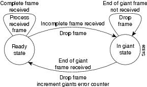
As shown in , a half-duplex DTE receive state machine for low-speed interfaces idles and receives frames in the ready state. A giant frame is any frame whose size exceeds the maximum transmission unit (MTU). If the beginning of a giant frame is received, the state machine transitions to the in giant state and discards frame fragments until it receives the end of the giant frame. At this point, the state machine transitions back to the ready state and waits for the next frame to arrive.
Figure 2 Half-Duplex DTE Receive State Machine
An error counter is incremented upon receipt of the giant frames. To view the error counter, enter the show interface command for the serial interface in question.
Half-Duplex DCE State Machines
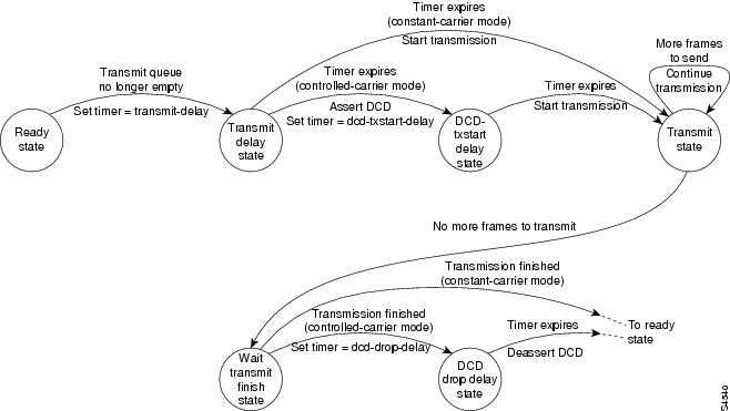
As shown in , for a low-speed serial interface in DCE mode, the half-duplex DCE transmit state machine idles in the ready state when it is quiescent. When a frame is available for transmission on the serial interface, such as when the output queues are no longer empty, the state machine starts a timer (based on the value the transmit-delay keyword, in milliseconds) and transitions to the transmit delay state. Similar to the DTE transmit state machine, the transmit delay state gives you the option of setting a delay between the transmission of frames; for example, this feature lets you compensate for a slow receiver that loses data when multiple frames are received in quick succession. Use the half-duplex timer transmit-delay value interface configuration command to specify a delay value not equal to 0. You can choose a value between the range of 0 to 4400 ms (4.4 seconds). The default is 0 ms.
Figure 3 Half-duplex DCE Transmit State Machine
After the transmit delay state, the next state depends on whether the interface is in constant-carrier mode (the default) or controlled-carrier mode.
If the interface is in constant-carrier mode, it transitions through the following states:
1
2
3
If the interface is in controlled-carrier mode, the interface performs a handshake using the data carrier detect (DCD) signal. In this mode, DCD is de-asserted when the interface is idle and has nothing to transmit. The transmit state machine transitions through the states as follows:
1
2
3
4
5
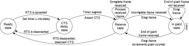
As shown in , the half-duplex DCE receive state machine idles in the ready state when it is quiescent. It transitions out of this state when the DTE asserts RTS. In response, the DCE starts a timer configured by the cts-delay keyword. This timer delays the assertion of CTS because some DTE interfaces expect this delay. Use the half-duplex timer cts-delay value interface configuration command to specify a delay value. The value you configure is dependent to the serial interface hardware installed.
Figure 4 Half-duplex DCE Receive State Machine
When the timer expires, the DCE state machine asserts CTS and transitions to the receive state. It stays in the receive state until there is a frame to receive. If the beginning of a giant frame is received, it transitions to the in giant state and keeps discarding all the fragments of the giant frame and transitions back to the receive state.
Transitions back to the ready state occur when RTS is de-asserted by the DTE. The response of the DCE to the de-assertion of RTS is to de-assert CTS and go back to the ready state.
Change between Controlled-Carrier and Constant-Carrier Modes
The half-duplex controlled-carrier command enables you to change between controlled-carrier and constant-carrier modes for low-speed serial DCE interfaces in half-duplex mode. Configure a serial interface for half-duplex mode by using the media-type half-duplex command. Full-duplex mode is the default for serial interfaces. This interface configuration is available on Cisco 2520 through Cisco 2523 routers.
Controlled-carrier operation means that the DCE interface will have DCD de-asserted in the quiescent state. When the interface has something to transmit, it will assert DCD, wait a user-configured amount of time, then start the transmission. When it has finished transmitting, it will again wait a user-configured amount of time, then de-assert DCD.
Place a Low-Speed Serial Interface in Controlled-Carrier Mode
To place a low-speed serial interface in controlled-carrier mode, perform the following task in interface configuration mode:
Place a low-speed serial interface in controlled-carrier mode.
half-duplex controlled-carrier
Place a Low-Speed Serial Interface in Constant-Carrier Mode
To return a low-speed serial interface to constant-carrier mode from controlled-carrier mode, perform the following task in interface configuration mode:
Place a low-speed serial interface in constant-carrier mode.
no half-duplex controlled-carrier
Change between Controlled-Carrier and Constant-Carrier Modes Example
The following example shows how to change to controlled-carrier mode from the default of constant-carrier operation:
Router(config)# interface serial 2Router(config-if)# half-duplex controlled-carrierThe following example shows how to change to constant-carrier mode from controlled-carrier mode:
Router(config)# interface serial 2Router(config-if)# no half-duplex controlled-carrierTune Half-Duplex Timers
To tune half-duplex timers, perform the following task in interface configuration mode:
The timer tuning commands permit you to adjust the timing of the half-duplex state machines to suit the particular needs of their half-duplex installation.
Note that the half-duplex timer command and its options deprecates the following two timer tuning commands that are available only on high-speed serial interfaces:
•
•
Tune Half-Duplex Timers Example
The following examples show how to set the cts-delay timer to 1234 ms and the transmit-delay timer to 50 ms.
Router(config)# interface serial 2Router(config-if)# half-duplex timer cts-delay 1234Router(config-if)# half-duplex timer transmit-delay 50Change between Synchronous and Asynchronous Modes
To specify the mode of a low-speed serial interface as either synchronous or asynchronous, perform the following task in interface configuration mode:
Specify the mode of a low-speed interface as either synchronous or asynchronous.
physical-layer {sync | async}
This command applies only to low-speed serial interfaces available on Cisco 2520 through Cisco 2523 routers.
In synchronous mode, low-speed serial interfaces support all interface configuration commands available for high-speed serial interfaces, except the following two commands:
•
•
When placed in asynchronous mode, low-speed serial interfaces support all commands available for standard asynchronous interfaces. The default is synchronous mode.
Note that when you enter this command, it does not appear in the output of show running config and show startup config command, because the command is a physical-layer command.
Return a Low-Speed Serial Interface to Synchronous Mode
To return to the default mode (synchronous) of a low-speed serial interface on a Cisco 2520 through Cisco 2523 router, perform the following task in interface configuration mode:
Specify the Mode of a Low-Speed Serial Interface Example
The following example shows how to change a low-speed serial interface from synchronous to asynchronous mode:
Router(config)# interface serial 2Router(config-if)# physical-layer asyncThe following examples show how to change a low-speed serial interface from asynchronous mode back to its default synchronous mode:
Router(config)# interface serial 2Router(config-if)# physical-layer syncorRouter(config)# interface serial 2Router(config-if)# no physical-layerThe following example shows some typical asynchronous interface configuration commands:
Router(config)# interface serial 2Router(config-if)# physical-layer asyncRouter(config-if)# ip address 1.0.0.2 255.0.0.0Router(config-if)# async default ip address 1.0.0.1Router(config-if)# async mode dedicatedRouter(config-if)# async default routingThe following example shows some typical synchronous serial interface configuration commands available when the interface is in synchronous mode:
Router(config)# interface serial 2Router(config-if)# physical-layer syncRouter(config-if)# ip address 1.0.0.2 255.0.0.0Router(config-if)# no keepaliveRouter(config-if)# ignore-dcdRouter(config-if)# nrzi-encodingRouter(config-if)# no shutdownConfigure Compression of PPP Data
You can configure point-to-point software compression on serial interfaces that use PPP encapsulation. Compression reduces the size of a PPP frame via lossless data compression. The compression algorithm used is a predictor algorithm (the RAND algorithm), which uses a compression dictionary to predict what the next character in the frame will be.
For HDLC encapsulations, you can specify a Stacker compression algorithm by using the stac keyword. PPP encapsulations support both predictor and Stacker compression algorithms.
Compression is performed in software and might significantly affect system performance. We recommend that you disable compression if CPU load exceeds 65 percent. To display the CPU load, use the show process cpu EXEC command.
If the majority of your traffic is already compressed files, it is recommended that you not use compression.
To configure compression over PPP, perform the following tasks in interface configuration mode:
Step 1
encapsulation ppp
Step 2
compress [predictor | stac]
Add a Description for an Interface
You can add a description about an interface to help you remember what is attached to it. This entry is meant solely as a comment to help identify what the interface is being used for. The description will appear in the output of the following commands: show startup-config, copy running-config, and show interfaces.
To add the description, complete the following task in interface configuration mode:
For examples of adding a description, see the section "Interface Configuration Examples" at the end of this chapter.
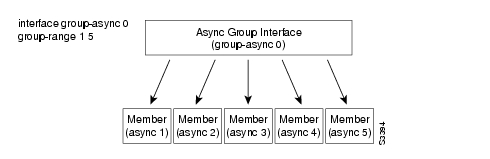
Configure Group and Member Asynchronous Interfaces
Using the interface group-async command, you can create an asynchronous interface to be used as a group interface. In turn, other asynchronous interfaces, known as "members," can be associated with this asynchronous group interface.
This association allows you to quickly configure the group interface and all of its member interfaces with a single command entered at the asynchronous group interface command line. You can have more than one group interface on a device; however, a member interface can only be associated with one group.
illustrates the group-member interface concept.
Figure 6-1 Group-Member Association on Asynchronous Interfaces
To create an asynchronous group interface and associate member interfaces to this group interface, perform the following commands starting in global configuration mode:
Refer to "Group and Member Asynchronous Interfaces Examples" for an example configuration.
Define Slave Asynchronous Interface Characteristics
Member interfaces can have certain interface configurations that differ from their group. The following are valid interface configuration commands:
•
•
To define a member to have one or more interface configurations different from its group, enter the following command in interface configuration mode, where interface-command is one of the commands listed in the preceding list:
Configure a member to have specific differences from its group.
member interface-number interface-command
Understand Subinterfaces
A subinterface is a mechanism that allows a single physical interface to support multiple logical interfaces or networks. That is, several logical interfaces or networks can be associated with a single hardware interface. Subinterfaces are implemented in various WAN and LAN protocols, including ATM, Frame Relay, SMDS, X.25, and Novell IPX. For more information about using subinterfaces, refer to the appropriate protocol chapter in this publication.
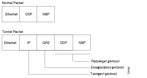
Understand Tunneling
Tunneling provides a way to encapsulate arbitrary packets inside of a transport protocol. This feature is implemented as a virtual interface to provide a simple interface for configuration. The tunnel interface is not tied to specific "passenger" or "transport" protocols, but rather, it is an architecture that is designed to provide the services necessary to implement any standard point-to-point encapsulation scheme.
Tunneling has three primary components:
•
•
•
•
•
•
To understand the process of tunneling, consider connecting two AppleTalk networks with a non-AppleTalk backbone, such as IP. The relatively high bandwidth consumed by the broadcasting of Routing Table Maintenance Protocol (RTMP) data packets can severely hamper the backbone's network performance. This problem can be solved by tunneling AppleTalk through a foreign protocol, such as IP. Tunneling encapsulates an AppleTalk packet inside the foreign protocol packet, which is then sent across the backbone to a destination access server. The destination access server then de-encapsulates the AppleTalk packet and, if necessary, routes the packet to a normal AppleTalk network. Because the encapsulated AppleTalk packet is sent in a directed manner to a remote IP address, bandwidth usage is greatly reduced. Furthermore, the encapsulated packet benefits from any features normally enjoyed by IP packets, including default routes and load balancing.
illustrates IP tunneling terminology and concepts.
Figure 6-2 IP Tunneling Terminology and Concepts
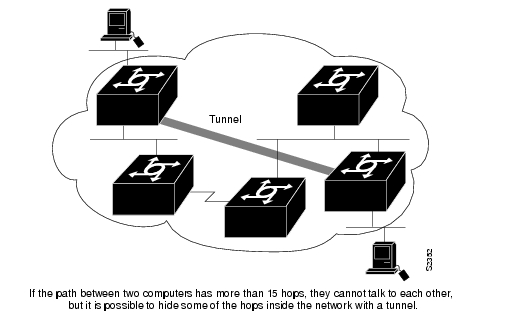
Advantages of Tunneling
There are several situations where encapsulating traffic in another protocol is useful:
•
•
•
•
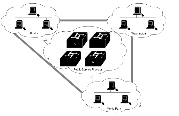
Figure 6-3 Providing Workarounds for Networks with Limited Hop Counts
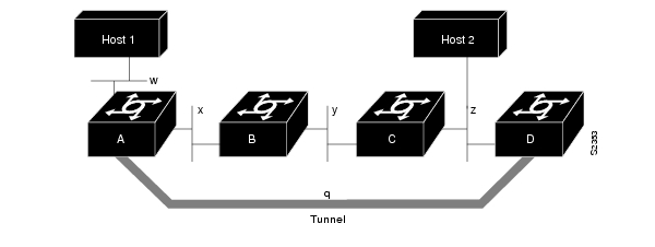
Special Considerations
The following are considerations and precautions to observe when configuring tunneling:
•
•
•
•
•
•
Figure 6-4 Tunnel Precautions: Hop Counts
•
•
•
•
If you see line protocol down, as in the following example, it might be because of a recursive route:
%TUN-RECURDOWN Interface Tunnel 0temporarily disabled due to recursive routingConfigure IP Tunneling
If you want to configure IP tunneling, you must perform the tasks in the following sections:
•
•
The tasks in the following tunnel configuration sections are optional:
•
•
•
•
For examples using these commands, see the section "IP Tunneling Examples" at the end of this chapter.
Configure the Tunnel Interface
To configure tunneling, you must configure the tunnel interface by performing the following task in global configuration mode:
Configure the Tunnel Source
You must specify the tunnel interface's source address by performing the following task in interface configuration mode:
Configure the tunnel source.
tunnel source {ip-address | interface-type interface-number}
Note
Configure the Tunnel Destination
You must specify the tunnel interface's destination by performing the following task in interface configuration mode:
Configure the Tunnel Mode
The encapsulation mode for the tunnel interface defaults to generic route encapsulation (GRE), so this task is considered optional. However, if you want a mode other than GRE, you must configure it by performing the following task in interface configuration mode:
If you are tunneling AppleTalk, you must use either AppleTalk Update Routing Protocol (AURP), Cayman or GRE tunneling mode. Cayman tunneling is designed by Cayman Systems, and enables access servers to interoperate with Cayman GatorBoxes. You can have a Cisco access server at either end of the tunnel, or you can have a GatorBox at one end and a Cisco access server at the other end. Use Distance Vector Multicast Routing Protocol (DVMRP) mode when an access server connects to a mrouted access server to run DVMRP over a tunnel. You must configure Protocol-Independent Multicast (PIM) and an IP address on a DVMRP tunnel.
CautionDo not configure a Cayman tunnel with an AppleTalk network address.
If you use GRE, you must have only our access servers at both ends of the tunnel connection. When using GRE to tunnel AppleTalk, you must configure an AppleTalk network address and a zone. Perform the following tasks to tunnel AppleTalk using GRE:
Step 1
interface tunneln
Step 2
appletalk cable-range start-end [network.node]1
Step 3
appletalk zone zone-name2
Step 4
tunnel source [interface | ip-address]
Step 5
tunnel destination ip-address
Step 6
tunnel mode gre ip
1 This command is documented in the "AppleTalk Commands" chapter of the Access and Communication Servers Command Reference publication.
2 This command is documented in the "AppleTalk Commands" chapter of the Access and Communication Servers Command Reference publication.
Configure End-to-End Checksumming
Some passenger protocols rely on media checksums to provide data integrity. By default, the tunnel does not guarantee packet integrity. By enabling end-to-end checksums, the access servers will drop corrupted packets. To enable such checksums on a tunnel interface, perform the following task in interface configuration mode:
Configure a Tunnel Identification Key
You can optionally enable an ID key for a tunnel interface. This key must be set to the same value on the tunnel endpoints. Tunnel ID keys can be used as a form of weak security to prevent misconfiguration or injection of packets from a foreign source.
The tunnel ID key is available with GRE only.
Note
To configure a tunnel ID key, perform the following task in interface configuration mode:
Configure a Tunnel Interface to Drop Out-of-Order Datagrams
You can optionally configure a tunnel interface to drop datagrams that arrive out of order. This is useful when carrying passenger protocols that behave poorly when they receive packets out of order (for example, LLC2-based protocols). This option is available with GRE only.
To use this option, perform the following task in interface configuration mode:
Monitor IP Tunnels
Complete any of the following tasks in EXEC mode to monitor the IP tunnels you have configured:
List tunnel interface information.
show interfaces tunnel unit [accounting]
List the routes that go through the tunnel.
show protocol route1
List the route to the tunnel destination.
show ip route2
1 This command is documented in the "System Management Commands" chapter in the Access and Communication Servers Command Reference publication.
2 This command is documented in the "IP Routing Protocols Commands" chapter in the Access and Communication Servers Command Reference publication.
Understand Asynchronous Host Mobility
Increasingly, mobile users are accessing networks through dial-up telephone connections. In contrast to local employees who can dial directly into an access server providing multiprotocol access to network resources, mobile users must often dial into an access server elsewhere on the organization's internetwork.
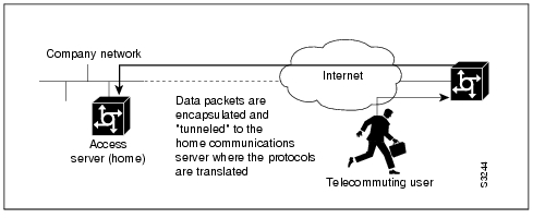
The access server supports a packet tunneling strategy that provides the host with mobility across the extended internetwork—in effect creating a virtual private network for the mobile user. When a user activates asynchronous host mobility, the access server on which the remote user dials into becomes a remote point-of-presence (POP) for the user's home network. Once logged in, the user experiences a server environment identical to the one that appears when he or she connects directly to the "home" access server.
Once the network layer connection is made, data packets are tunneled at the physical and/or data link layer instead of at the protocol layer. In this way, raw data bytes from dial-in users are transported directly to the "home" access server, which processes the protocols.
illustrates the implementation of asynchronous host mobility on an extended internetwork. A mobile user connects to an access server on the internetwork and, by activating asynchronous host mobility, is connected to a "home" access server configured with the appropriate username. The user sees an authentication dialog or prompt from the "home" system and can proceed as if he or she were connected directly to that device.
Figure 6-5 Asynchronous Host Mobility
The remote user implements asynchronous host mobility by executing a User EXEC tunnel command. When executed, the command sets up a network layer connection to the destination specified in the command. The access server accepts the connection, attaches it to a virtual terminal (VTY), and runs a command parser capable of running the normal dial-in services. After the connection is established, data is transferred between the modem and network connection with a minimum of interpretations. When communications are complete, the network connection can be closed and terminated from either end.
Refer to the Cisco Access Connection Guide for information about setting up the network layer connection with the tunnel command.
Configure Synchronous Serial Features
The optional tasks in the following sections configure features on a synchronous serial interface:
•
•
•
•
Reenable HDLC Serial Encapsulation
The access server provides HDLC encapsulation for serial lines by default. This encapsulation method provides the synchronous framing and error detection functions of HDLC without windowing or retransmission. Although it is the default, it can be reenabled as the encapsulation method, if necessary, by performing the following task in interface configuration mode:
Configure Compression of HDLC Data
You can configure point-to-point software compression on serial interfaces that use HDLC encapsulation. Compression reduces the size of a HDLC frame via lossless data compression. The compression algorithm used is a Stacker (LZS) algorithm.
Compression is performed in software and might significantly affect system performance. We recommend that you disable compression if CPU load exceeds 65%. To display the CPU load, use the show process cpu EXEC command.
If the majority of your traffic is already compressed files, you should not use compression.
To configure compression over HDLC, perform the following tasks in interface configuration mode:
Step 1
encapsulation hdlc
Step 2
compress stac
Configure Compression of LAPB Data
You can configure point-to-point software compression on serial interfaces that use LAPB or multi-LAPB encapsulation. Compression reduces the size of a LAPB or multi-LAPB frame via lossless data compression. The compression algorithm used is a predictor algorithm (the RAND algorithm), which uses a compression dictionary to predict what the next character in the frame will be.
Compression is performed in software and might significantly affect system performance. We recommend that you disable compression if CPU load exceeds 65%. To display the CPU load, use the show process cpu EXEC command.
Predictor compression is recommended when the bottleneck is the load on the router; Stacker compression is recommended when the bottleneck is line bandwidth. Compression is not recommended if the majority of your traffic is already compressed files. Compression is also not recommended for linespeeds greater than T1; the added processing time will slow performance on such lines.
To configure compression over LAPB, perform the following tasks in interface configuration mode:
Step 1
encapsulation lapb
Step 2
compress [predictor | stac]
To configure compression over multi-LAPB, perform the following tasks in interface configuration mode:
Step 1
encapsulation lapb multi
Step 2
compress [predictor | stac]
When using compression, the MTU for the serial interface and the LAPB N1 parameter should be adjusted as in the following example, in order to avoid informational diagnostics regarding excessive MTU or N1 sizes:
interface serial 0encapsulation lapbcompress predictormtu 1509lapb n1 12072For information about configuring X.25 TCP/IP header compression and X.25 payload compression, see the chapter "Configuring X.25 and LAPB."
Set Transmit Delay
It is possible to send back-to-back data packets over serial interfaces faster than some hosts can receive them. You can specify a minimum dead time after transmitting a packet to alleviate this condition. This setting is available for serial interfaces on the MCI and SCI interface cards. Perform one of the following tasks, as appropriate for your system, in interface configuration mode:
Set the transmit delay on the MCI and SCI synchronous serial interfaces.
transmitter-delay microseconds
Configure DTR Signal Pulsing
You can configure pulsing DTR signals on all serial interfaces.When the serial line protocol goes down (for example, because of loss of synchronization) the interface hardware is reset and the DTR signal is held inactive for at least the specified interval. This function is useful for handling encrypting or other similar devices that use the toggling of the DTR signal to resynchronize.To configure DTR signal pulsing, perform the following task in interface configuration mode:
Configure the Clock Rate on DCE Appliques
You can configure the clock rate for appliques (connector hardware) on the serial interface of the MCI and SCI cards to an acceptable bit rate. To do so, perform the following task in interface configuration mode:
Configure Snapshot Routing
Snapshot routing, which is available on serial lines, is a method of learning remote routes dynamically and then keeping the routes available for a period of time while regular routing updates are not being exchanged. This might be during periods when a remote site has not dialed into the local site or when a remote site has a dedicated connection to the local site but wishes to avoid the overhead of exchanging routing updates. Snapshot routing allows you to avoid configuring static routes when using dial-on-demand routing. It also eliminates the overhead required for sending periodic updates over dedicated serial lines.
When configuring snapshot routing, you choose one router on the interface to be the client router and one or more other routers to be server routers. The client router determines the frequency at which routing information is exchanged between routers.
Routing information is exchanged during an active period. At the end of this period, the router takes a snapshot of the entries in the routing table. These entries remain frozen during a quiet period. At the end of the quiet period, another active period starts during which routing information is again exchanged. See .
Figure 6-6 Active and Quiet Periods in Snapshot Routing
When the router transitions from the quiet period to the active period, the line might not be available for a variety of reasons. For example, the line might be down or busy, or the PVC might be down. If this happens, the router has to wait through another entire quiet period before it can update its routing table entries. This might be a problem if the quiet period is very long, for example, around 12 hours. To avoid having to wait through the quiet period, you can configure a retry period. If the line is not available when the quiet period ends, the router waits for the amount of time specified by the retry period and then transitions to an active period. See .
Figure 6-7 Retry Period in Snapshot Routing
Snapshot routing is useful in two command situations:
•
•
The following routing protocols support snapshot routing. Note that these are all distance-vector protocols.
•
•
•
•
To configure snapshot routing, perform the tasks described in the following sections. The tasks in the first two sections are required; those in the remaining section are optional:
•
Configure the Client Router
To configure snapshot routing on the client router that is connected to a dedicated serial line, perform the following steps starting in global configuration mode:
Step 1
interface serial number
Step 2
snapshot client active-time quiet-time [suppress-statechange-updates] [dialer]
To configure snapshot routing on the client router connected to an interface configured for DDR, perform the following steps starting in global configuration mode:
Repeat Step 5 for each map you want to define.
Configure the Server Router
To configure snapshot routing on the server router that is connected to a dedicated serial line, perform the following steps starting in global configuration mode:
Step 1
interface serial number
Step 2
snapshot server active-time [dialer]
The active period for the client router and its associated server routers should be the same.
Monitor and Maintain Snapshot Routing
To monitor and maintain snapshot routing, perform one or both of the following tasks in EXEC mode:
Terminate the quiet period on the client router within two minutes.
clear snapshot quiet-time interface
Display information about snapshot routing parameters.
show snapshot interface
Assigning IP Addresses to an Incoming Connection
You can assign IP addresses to incoming connections on an asynchronous interface without a known IP address in one of three ways:
•
•
•
Address pooling allows a set of IP addresses to be allocated for users without a known IP address who are dialing in to the access server. This allows a finite number of IP addresses to be reused quickly and efficiently by many clients. Additional benefits include the ability to maintain sessions, such as Telnet, even when a modem line fails. When the client is auto-dialed back into the server, the server will attempt to reissue the same IP address to the client and therefore resume the aborted session.
You can create address pools with the Dynamic Host Configuration Protocol (DHCP) suite of commands, or with the ip local pool command. Alternately, you can assign a single IP address to be used on a specific interface by using the peer default ip-address command. This has the same effect as turning off pooling on this interface. These methods are described in the following sections.
Configure DHCP Address Pooling
The Dynamic Host Configuration Protocol (DHCP) model consists of the following components:
•
•
The DHCP client-proxy feature manages a pool of IP addresses available to PPP or SLIP dial-in clients without a known IP address. You can designate all of the access server's asynchronous interfaces to use DHCP or you can turn off DHCP on individual interfaces. You can also assign a specific IP address to use on a given interface (see the section "Configure Specific IP Addresses for an Interface.") Cisco's implementation of DHCP complies with RFC 1541, and is compliant with Extended TACACS and AAA/TACACS+.
To enable DHCP address pooling on the access server's asynchronous interfaces, perform the following tasks, starting in global configuration mode:
Refer to "Configure DHCP Pooling Examples" for examples of these tasks.
Turn off DHCP Address Pooling on an Interface
To turn off DHCP address pooling on a specific interface, perform the following task in interface configuration mode:
Turn off DHCP on any asynchronous interfaces on the access server, as needed.
no peer default ip address
Configure Local IP Address Pooling
To make temporary IP addresses available for dial-in asynchronous clients using SLIP or PPP on a per-interface basis, perform the following tasks, beginning in global configuration mode:
Refer to "Configure Local Pooling Example" for examples of these tasks, and to the chapter "Protocol Translation" for information on how to assign IP addresses dynamically on a virtual asynchronous connection.
Turn off Local IP Address Pooling on an Interface
To turn off local IP address pooling on a specific interface, perform the following task in interface configuration mode:
Turn off local IP address pooling on any asynchronous interfaces on the access server.
no peer default ip address
Configure Specific IP Addresses for an Interface
To specify that a specific IP address be returned when an incoming connection requests an address, perform the following tasks, beginning in interface configuration mode:
Step 1
peer default ip address address
You can use this command in conjunction with DHCP or local address pooling. Refer to "Configure Specific IP Addresses for an Interface Example " for an example of these tasks.
Configure IP Address Pooling on Point-to-Point Links
Point-to-point interfaces must be able to provide a remote node with its IP address through the IP Control Protocol (IPCP) address negotiation process. The IP address can be obtained from a variety of sources. The address can be configured through the command line, entered with an EXEC-level command, or provided by TACACS+, DHCP, or from a locally administered pool.
IP address pooling provides a pool of IP addresses from which an incoming interface can provide an IP address to a remote node through the IP Control Protocol (IPCP) address negotiation process. It also enhances the flexibility of configuration by allowing multiple types of pooling to be active simultaneously.
The IP address pooling feature now allows configuration of a global default address pooling mechanism, a per-interface configuration of the mechanism to use, and a per-interface configuration of a specific address or pool name to use.
Peer Address Allocation
A peer IP address can be allocated to an interface through several methods:
•
•
•
•
•
•
•
•
•
The pool configured for the interface is used, unless TACACS+ returns a pool name as part of AAA. If no pool is associated with a given interface, the global pool named default is used.
Precedence Rules
The following precedence rules of peer IP address support determine which address is used. Precedence is listed from highest to lowest:
•
•
•
•
•
•
Interfaces Affected
This feature is available on all asynchronous serial, synchronous serial, ISDN BRI, and ISDN PRI interfaces running PPP or SLIP.
Choose the IP Address Assignment Method
The IP address pooling feature now allows configuration of a global default address pooling mechanism, a per-interface configuration of the mechanism to use, and a per-interface configuration of a specific address or pool name to use.
You can define the IP address pooling mechanism to be used on router interfaces as described in the following sections:
•
•
Define the Global Default Mechanism
The Global Default Mechanism applies to all point-to-point interfaces (asynchronous, synchronous, ISDN BRI, ISDN PRI, and dialer interfaces) that support PPP encapsulation and that are not configured for IP address pooling. You can define the Global Default Mechanism to be either DHCP or local address pooling.
To configure the Global Default Mechanism for IP address pooling, perform the tasks in one of following sections:
•
•
After you have defined a Global Default Mechanism, you can disable it on a specific interface by configuring the interface for some other pooling mechanism. You can define a local pool other than the default pool for the interface or you can configure the interface with a specific IP address to be used for dial-in peers.
Define DHCP as the Global Default Mechanism
The Dynamic Host Configuration Protocol (DHCP) specifies the following components:
•
•
To enable DHCP as the Global Default Mechanism, complete the following tasks in global configuration mode:
In Step 2, you can provide as few as one or as many as ten DHCP servers for the proxy-client (the Cisco router or access server) to use. DHCP servers provide temporary IP addresses.
Define Local Address Pooling as the Global Default Mechanism
To specify local pooling as the Global Default Mechanism to use, complete the following tasks in global configuration mode:
If no other pool is defined, the local pool called default is used.
Configure Per-Interface IP Address Assignment
When you have defined a Global Default Mechanism for assigning IP addresses to dial-in peers, you can then configure the few interfaces for which it is important to have a nondefault configuration.
You can define a nondefault address pool for use by this specific interface, you can define DHCP on this interface even if you have defined local pooling as the Global Default Mechanism, or you can specify one IP address to be assigned to all dial-in peers on this interface.
To define a nondefault address pool for use on this interface, perform the following tasks beginning in global configuration mode:
To define DHCP as the IP address mechanism for this interface, complete the following tasks beginning in global configuration mode:
Specify the interface and enter interface configuration mode.
interface type number
Specify DHCP as the IP address mechanism on this interface.
peer default ip address pool dhcp
To define a specific IP address to be assigned to all dial-in peers on this interface, complete the following tasks beginning in global configuration mode:
Specify the interface and enter interface configuration mode.
interface type number
Specify the IP address to assign.
peer default ip address ip-address
Select the Ethernet Encapsulation
Ethernet interfaces on the access server support several encapsulation methods, depending upon the application type code and media type, as follows:
•
•
•
Establish Ethernet encapsulation by selecting one of the Ethernet encapsulation methods, using the appropriate command in interface configuration mode, as follows:
Select ARPA Ethernet encapsulation.
encapsulation arpa
Select SAP Ethernet encapsulation.
encapsulation sap
Select SNAP Ethernet encapsulation.
encapsulation snap
Configure MOP
Perform the tasks in this section to configure the Maintenance Operation Protocol (MOP).
Enable MOP
You can enable MOP on an interface by performing the following task in interface configuration mode:
Enable MOP Message Support
You can enable an interface to send out periodic MOP system identification messages on an interface by performing the following task in interface configuration mode:
Configure Token Ring Features
Perform the tasks in this section to configure Token Ring features.
Select the Token Ring Speed
The Token Ring interface on the CSC-1R and CSC-2R can run at either 4 or 16 Mbps. Token Ring interfaces do not default to any particular ring speed; you must select the speed the first time you use them.
CautionConfiguring a ring speed that is wrong or incompatible with the connected Token Ring causes the ring to beacon, which effectively takes the ring down and makes it nonoperational.
Configure the ring speed on the CSC-1R or CSC-2R Token Ring interfaces by performing the following task in interface configuration mode:
You do not need to select the ring speed for the CSC-R16 Token Ring interface card.
Enable Early Token Release
Our Token Ring interfaces support early token release, a method whereby the interface releases the token back onto the ring immediately after transmitting rather than waiting for the frame to return. This feature can help to increase the total bandwidth of the Token Ring. To configure the interface for early token release, perform the following task in interface configuration mode:
Configure the Point-to-Point Protocol
The Point-to-Point Protocol (PPP), described in RFCs 1331 and 1332, is a method of encapsulating network layer protocol information over point-to-point links.
IP and IPX upper-layer protocols are supported.
The software provides PPP as an encapsulation method. It also provides the Challenge Handshake Authentication Protocol (CHAP) and Password Authentication Protocol (PAP) on serial interfaces running PPP encapsulation. The following sections describe the tasks to configure these features.
Enable PPP Encapsulation
You can enable the Point-to-Point Protocol on serial lines to encapsulate IP and SLIP datagrams. To do so, perform the following task in interface configuration mode:
Enable CHAP or PAP Authentication
Access control using Challenge Handshake Authentication Protocol (CHAP) or Password Authentication Protocol (PAP) is available on all serial interfaces (high and low speed) that use PPP encapsulation. The authentication feature reduces the risk of security violations on your access server. You can configure either CHAP or PAP for the interface.
Note
When CHAP is enabled on an interface, the local access server sends a CHAP packet and the remote device (a PC, workstation, router, or access server) that attempts to connect to the local access server or router is requested, or "challenged," to respond.
The challenge consists of an ID, a random number, and either the host name of the local access server or the name of the user on the remote device. This challenge is transmitted to the remote device.
The required response consists of two parts:
•
•
When the local access server receives the challenge response, it verifies the secret by looking up the name given in the response and performing the same encryption operation. The secret passwords must be identical on the remote device and the local access server or router.
By transmitting this response, the secret is never transmitted, preventing other devices from stealing it and gaining illegal access to the system. Without the proper response, the remote device cannot connect to the local access server.
CHAP transactions occur only at the time a link is established. The local access server does not request a password during the rest of the call. (The local access server can, however, respond to such requests from other devices during a call.)
To use CHAP, you must perform the following tasks:
1
Once you have enabled CHAP, the local access server requires a password from remote devices. If the remote device does not support CHAP, no traffic will be passed to that device.
2
Configure the secret or password for each remote system with which authentication is required. As an alternative, you can also configure TACACS.
Perform the following tasks in interface configuration mode:
Step 1
ppp authentication {chap | pap} [if-needed]
or
ppp authentication {chap | pap} [list-name]Step 2
or
configure TACACS.username name password secret1
ppp use-tacacs [single-line]
1 These commands are documented in the "System Management Commands" chapter of the Access and Communication Servers Command Reference publication.
The optional argument if-needed can only be used with TACACS or XTACACS. The optional keyword list-name can only be used with AAA/TACACS+. CHAP is specified in RFC 1334. It is an additional authentication phase of the PPP Link Control Protocol.
For an example of CHAP, see the section "CHAP with an Encrypted Password Example" at the end of this chapter. CHAP is specified in the IETF RFC 1334 "The PPP Authentication Protocols" by Brian Lloyd of Lloyd and Associates and William A. Simpson of Computer Systems Consulting Services. CHAP is specified as an additional authentication phase of the PPP Link Control Protocol.
Enable Link Quality Monitoring
Link Quality Monitor (LQM) is available on all serial interfaces running PPP. LQM monitors the link quality and takes the link down when the quality drops below a configured percentage. The percentages are calculated for both the incoming and outgoing directions. The outgoing quality is calculated by comparing the total number of packets and bytes sent with the total number of packets and bytes received by the peer. The incoming quality is calculated by comparing the total number of packets and bytes received with the total number of packets and bytes sent by the peer.
When LQM is enabled, Link Quality Reports (LQRs) are sent every keepalive period. LQRs are sent in place of keepalives. All incoming keepalives are responded to properly. If LQM is not configured, keepalives are sent every keepalive period and all incoming LQRs are responded to with an LQR.
LQR is specified in the IETF RFC-1333, "PPP Link Quality Monitoring" by William A. Simpson of Computer Systems Consulting Services. The latest version is dated May 1992.
To enable LQM on the interface, perform the following task in interface configuration mode:
The percentage argument specifies the link quality threshold. That percentage must be maintained, or the link is deemed to be of poor quality and taken down.
PPP Magic Number Support
Magic Number support is available on all serial interfaces. When using PPP, PPP will always attempt to negotiate for Magic Numbers, which are used to detect looped-back nets. The link might or might not be taken down upon looped-back detection, depending on the use of the down-when-looped command.
Configure Dial Backup Service
To configure dial backup, associate a secondary serial interface as a backup to a primary serial interface. This feature requires that an external modem or CSU/DSU device attached to a circuit-switched service be connected on the secondary serial interface. The external device must be capable of responding to a DTR signal (DTR active) by automatically dialing a connection to a preconfigured remote site.
The dial backup software keeps the secondary line inactive (DTR inactive) until one of the following conditions is met:
•
•
These conditions are defined using the interface configuration commands described later in this section.
When the software detects a lost Carrier Detect signal from the primary line device or finds that the line protocol is down, it activates DTR on the secondary line. At that time, the modem or CSU/DSU device must be set to dial the remote site. When that connection is made, the routing protocol defined for the serial line will continue the job of transmitting traffic over the dialup line.
You also can configure the dial backup feature to activate the secondary line based upon traffic load on the primary line.
The software monitors the traffic load and computes a five-minute moving average. If this average exceeds the value you set for the line, the secondary line is activated, and depending upon how the line is configured, some or all of the traffic will flow onto the secondary dialup line.
Perform the following tasks in interface configuration mode:
See the section "Dial Backup Service Examples" at the end of this chapter for examples of dial backup configuration.
For more information about dial backup, refer to the chapter "Configuring Dial-on-Demand Routing" later in this manual.
Ignore DCD and Monitor DSR as Line Up/Down Indicator
This task applies to Quad Serial NIM interfaces on the Cisco 4000 series and Hitachi-based serial interfaces on the Cisco 2500 series and Cisco 3000 series.
By default, when the serial interface is operating in DTE mode, it monitors the Data Carrier Detect (DCD) signal as the line up/down indicator. By default, the attached DCE device sends the DCD signal. When the DTE interface detects the DCD signal, it changes the state of the interface to up.
In some configurations, such as an SDLC multidrop environment, the DCE device sends the Data Set Ready (DSR) signal instead of the DCD signal, which prevents the interface from coming up. To tell the interface to monitor the DSR signal instead of the DCD signal as the line up/down indicator, perform the following task in interface configuration mode:
Configure the serial interface to monitor the DSR signal as the line up/down indicator.
ignore-dcd
Configure Loopback Detection
When an interface has a backup interface configured, it is often desirable that the backup interface be enabled when the primary interface is either down or in loopback. By default, the backup is only enabled if the primary interface is down. By using the down-when-looped command, the backup interface will also be enabled if the primary interface is in loopback. To achieve this condition, perform the following task in interface configuration mode:
Configure an interface to tell the system it is down when loopback is detected.
down-when-looped
If testing an interface with the loopback command, down-when-looped should not be configured, or packets will not be transmitted out the interface that is being tested.
Control Interface Hold-Queue Limits
Each interface has a hold-queue limit. This limit is the number of data packets that the interface can store in its hold queue before rejecting new packets. When the interface empties one or more packets from the hold queue, the interface can accept new packets again. You can specify the hold-queue limit of an interface in interface configuration mode as follows:
Specify the maximum number of packets allowed in the hold queue.
hold-queue length {in | out}
Set Bandwidth
Higher-level protocols use bandwidth information to make operating decisions. For example, IGRP uses the minimum path bandwidth to determine a routing metric. The TCP protocol adjusts initial retransmission parameters based on the apparent bandwidth of the outgoing interface. Perform the following task in interface configuration mode to set a bandwidth value for an interface:
The bandwidth setting is a routing parameter only; it does not affect the physical interface.
Set Interface Delay
Higher-level protocols might use delay information to make operating decisions. For example, IGRP can use delay information to differentiate between a satellite link and a land link. To set a delay value for an interface, perform the following task in interface configuration mode:
Specifying the delay value sets an informational parameter only; you cannot adjust the actual delay of an interface with this configuration command.
Adjust Timers
To adjust the frequency of update messages, perform the following task in interface configuration mode:
You also can configure the keepalive interval, the frequency at which the access server sends messages to itself (Ethernet and Token Ring) or to the other end (HDLC-serial, PPP-serial) to ensure that a network interface is alive. The interval in some previous software versions was 10 seconds; it is now adjustable in one-second increments down to one second. An interface is declared down after three update intervals have passed without receiving a keepalive packet.
When adjusting the keepalive timer for a very low bandwidth serial interface, large packets can delay the smaller keepalive packets long enough to cause the line protocol to go down. You might need to experiment to determine the best value.
Limit Size of the Transmit Queue
You can control the size of the transmit queue available to a specified interface on the MCI and SCI cards. To limit the size, perform the following task in interface configuration mode:
Adjust Maximum Packet Size or MTU Size
Each interface has a default maximum packet size or maximum transmission unit (MTU) size. This number generally defaults to 1500 bytes. On serial interfaces, the MTU size varies, but cannot be set smaller than 64 bytes. To adjust the maximum packet size, perform the following task in interface configuration mode:
Monitor and Maintain the Interface
You can perform the tasks in the following sections to monitor and maintain the interfaces:
•
•
•
Monitor Interface Status
The software contains commands that you can enter at the EXEC prompt to display information about the interface, including the version of the software and the hardware, the controller status, and statistics about the interfaces. The following table lists some of the interface monitoring tasks. (The full list of show commands can be displayed by entering the show ? command at the EXEC prompt.) These commands are fully described in the Access and Communication Servers Command Reference publication.
Perform the following commands in EXEC mode:
Display the status of an asynchronous interface.
show async status
Display compression statistics on a serial interface.
show compress
Display current internal status information for the interface controller cards.
show controllers {mci | serial | token}
Display the number of packets of each protocol type that have been sent through the interface.
show interfaces [type {unit}] [accounting]
Display the number of packets of each protocol type that have been sent through the asynchronous serial line.
show interfaces async [unit] [accounting]
Display the current contents of the Token Ring routing information field (RIF) cache.
show rif
Display the hardware configuration, software version, the names and sources of configuration files, and the boot images.
show version1
1 This command is documented in the "System Image, Microcode Image, and Configuration File Load Commands" chapter of the Access and Communication Servers Command Reference publication.
Clear and Reset the Interface
To clear the interface counters shown with the show interfaces command, enter the following command at the EXEC prompt:
Note
Complete the following tasks in EXEC mode to clear and reset interfaces. Under normal circumstances, you do not need to clear the hardware logic on interfaces.
Shut Down and Restart an Interface
You can disable an interface. Doing so disables all functions on the specified interface and marks the interface as unavailable on all monitoring command displays. This information is communicated to other network servers through all dynamic routing protocols. The interface will not be mentioned in any routing updates. On serial interfaces, this command causes the DTR signal to be dropped. On Token Ring interfaces, this command causes the interface to deinsert from the ring.
To shut down an interface and then restart the disabled interface, perform the following tasks in interface configuration mode:
To check whether an interface is disabled, use the EXEC command show interfaces. An interface that has been shut down is shown as administratively down in the show interfaces command display. See examples in the section "Interface Shutdown Examples" at the end of this chapter.
Run Interface Loopback Diagnostics
You can use a loopback test on lines to detect and distinguish equipment malfunctions between line and modem or Channel Service Unit/Digital Service Unit (CSU/DSU) problems on the network server. If correct data transmission is not possible when an interface is in loopback mode, the interface is the source of the problem. The DSU might have similar loopback functions you can use to isolate the problem if the interface loopback test passes. If the device does not support local loopback, this function will have no effect.
You can specify hardware loopback tests on the Ethernet and synchronous serial interfaces, and all Token Ring interfaces (except the CSC-R 4-megabit card) that are attached to CSU/DSUs, and that support the local loopback signal. The CSU/DSU acts as a data communications equipment (DCE) device; the access server acts as a data terminal equipment (DTE) device. The local loopback test generates a CSU loop—a signal that goes through the CSU/DSU to the line, then back through the CSU/DSU to the access server. The ping command can also be useful during loopback operation.
The loopback tests are available on the following interfaces:
•
•
•
The following sections describe each test.
Note
Enable Loopback on MCI and SCI Serial Cards
The MCI and SCI serial interface cards support the loopback function when a CSU/DSU or equivalent device is attached to the access server. Perform the following task in interface configuration mode:
Enable loopback through a CSU/DSU to configure a CSU loop on the MCI and SCI synchronous serial interfaces.
loopback
Enable Loopback on MCI and MEC Ethernet Cards
The Ethernet interfaces on the MCI and MEC cards support loopback mode. To enable loopback mode on them, perform the following task in interface configuration mode:
Enable loopback to verify that the interface receives back every packet it sends.
loopback
Configure the Ethernet Loopback Server
The access server software provides an Ethernet loopback server that supports Digital, Intel, and Xerox systems specified by the "blue book," a joint specification written by Digital, Intel, and Xerox that defines the Ethernet protocol. The loopback server responds to forward data loopback messages sent either to the server's MAC address or to the broadcast address. Currently, the Ethernet loopback server does not respond to the loopback assistance multicast address.
Use the Ethernet loopback server to test communications between your internetworking products and Digital systems that do not support the IP ping command, such as DECnet-only VMS systems.
To originate a loop test on your VMS system with a Cisco server, use the Digital Network Control Program (NCP) command Loop Circuit. For more information about the Loop Circuit command, consult the DECnet VAX documentation. Cisco network servers support all options that can be specified by the VMS hosts.
Enable Loopback on Token Ring Cards
You can place all of the Token Ring interface cards except the 4-MB CSC-R card into loopback mode by performing the following task in interface configuration mode:
Enable loopback to verify that the Token Ring interface receives back every packet it sends.
loopback
Interface Configuration Examples
Use the configuration examples in the following sections to understand some aspects of interface configuration:
•
•
•
•
•
•
•
•
Enabling Interface Configuration Example
The following example illustrates how to begin interface configuration. It assigns Point-to-Point (PPP) encapsulation to serial interface 0.
interface serial 0encapsulation pppRestricted Access on the Asynchronous Interface Example
The following example assumes that users are restricted to certain servers designated as asynchronous servers, but that normal terminal users can access anything on the local network:
! access list for normal connectionsaccess-list 1 permit 172.30.0.0 0.0.255.255!access-list 2 permit 172.30.42.55access-list 2 permit 172.30.111.1access-list 2 permit 172.30.55.99!interface async 1async dynamic addressip access-group 1 outip access-group 2 inPPP Connection Example
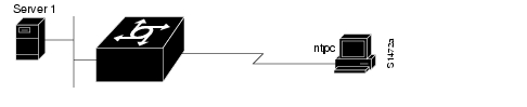
In the following example, a line that is in asynchronous mode is using PPP encapsulation (see
). The IP address of the PC is ntpc (assuming that the name ntpc is in the DNS so that it can be resolved to a real IP address). The person typing this command is using a PC that is running a terminal emulator program.Router> ppp ntpc@server1 /routing /compressedFigure 6-8 Using the PPP EXEC Command
SLIP and PPP Connection Examples
The following example shows how to make a connection when a permanent address is assigned and dynamic addressing is not allowed. An authentication request is sent to the TACACS server, and if it is approved, the line is placed in SLIP mode and the IP address is displayed.
Router> slip
Entering SLIP mode.
Your IP address is 172.30.7.28, MTU is 1500 bytesThe following example illustrates the prompts displayed and the response required when dynamic addressing is used to assign the SLIP address:
Router> slip IP address or hostname? 172.30.6.15Password:Entering SLIP modeYour IP address is 172.30.6.15, MTU is 1500 bytesThe following example illustrates the implementation of header compression on the interface with the IP address 172.30.2.1:
Router> slip /compressed 172.30.2.1Password:Entering SLIP mode.Interface IP address is 172.30.2.1, MTU is 1500 bytes.Header compression is On.In the following example, header compression is configured as passive, so the status of header compression is assigned by the user-level slip or ppp command:
Router> slip 1.0.0.1@checkPassword:Entering SLIP mode.Interface IP address is 1.0.0.1, MTU is 1500 bytesHeader compression will match your system.Interface Description Examples
The following example illustrates how to add a description about an interface that will appear in configuration files and monitoring command displays:
interface ethernet 0description First Ethernet in network 1ip address 172.30.15.78 255.255.255.0Interface Shutdown Examples
The following example turns off Ethernet interface 0:
interface ethernet 0shutdownThe following example turns the interface back on:
interface ethernet 0no shutdownThe following example illustrates how to shut down a Token Ring interface:
interface tokenring 0shutdownGroup and Member Asynchronous Interfaces Examples
The following example shows how to create an asynchronous group interface 0 with group interface members 2 through 7, starting in global configuration mode:
interface group-async 0
 group-range 2 7
The following example shows how you need to configure asynchronous interfaces 1, 2, and 3 separately if you do not have a group interface configured:
!interface Async1ip unnumbered Ethernet0encapsulation pppasync default ip address 172.30.1.1async mode interactiveasync dynamic routing!interface Async2ip unnumbered Ethernet0encapsulation pppasync default ip address 172.30.1.2async mode interactiveasync dynamic routing!interface Async3ip unnumbered Ethernet0!encapsulation pppasync default ip address 172.30.1.3async mode interactiveasync dynamic routingThe following example configures the same interfaces, but from a single group asynchronous interface:
!interface Group-Async 0ip unnumbered Ethernet0encapsulation pppasync mode interactiveasync dynamic routinggroup-range 1 3member 1 async default ip address 172.30.1.1member 2 async default ip address 172.30.1.2member 3 async default ip address 172.30.1.3IP Tunneling Examples
shows a configuration that will route a private IP network and a Novell network across a Public Service Provider. The configurations for access servers A and B follow .
Figure 6-9 Creating Virtual Private Networks across WANs
Access Server A
interface ethernet 0description boston officeip address 172.30.1.1 255.255.255.0novell network 1einterface serial 0description connection to NEARnetip address 172.30.2.1 255.255.255.0interface tunnel 0tunnel source serial 0tunnel destination 131.108.5.2ip address 172.30.2.1 255.255.255.0novell network 1fAccess Server B
interface ethernet 0description menlo park officeip address 172.30.3.1 255.255.255.0novell network 31interface serial 4description connection to BARRnetip address 1172.30.5.2 255.255.255.0interface tunnel 0tunnel source serial 4tunnel destination 192.13.2.1ip address 172.30.2.2 255.255.255.0novell network 1fCHAP with an Encrypted Password Example
The following configuration examples enable CHAP on serial interface 0 of three access servers.
Access Server yyy
hostname yyyinterface serial 0encapsulation pppppp authentication chapusername xxx password secretxyusername zzz password secretzyAccess Server xxx
hostname xxxinterface serial 0encapsulation pppppp authentication chapusername yyy password secretxyusername zzz password secretxzAccess Server zzz
hostname zzzinterface serial 0encapsulation pppppp authentication chapusername xxx password secretxzusername yyy password secretzyWhen you look at the configuration file, the passwords will be encrypted and the display will look similar to the following:
hostname xxxinterface serial 0encapsulation pppppp authentication chapusername yyy password 7 121F0A18username zzz password 7 1329A055Dial Backup Service Examples
The dial backup service examples show configurations for the following conditions:
•
•
•
When the Primary Line Goes Down
The following example configures serial 1 as a secondary line that activates only when the primary line (serial 0) goes down. The secondary line will not be activated due to load of the primary.
interface serial 0backup interface serial 1backup delay 30 60The secondary line is configured to activate 30 seconds after the primary line goes down and to remain on for 60 seconds after the primary line is reactivated.
When the Primary Line Reaches Threshold
The following example configures the secondary line (serial 1) to be activated only when the load of the primary line reaches a certain threshold:
interface serial 0backup interface serial 1backup load 75 5In this case, the secondary line will not be activated when the primary line goes down. The secondary line will be activated when the load on the primary line is greater than 75 percent of the primarys line's bandwidth. The secondary line will then be brought down when the aggregate load between the primary and secondary lines fits within 5 percent of the primary bandwidth.
When the Primary Line Exceeds Threshold
This example configures the secondary line to activate once the traffic threshold on the primary line exceeds 25 percent:
interface serial 0backup interface serial 1backup load 25 5backup delay 10 60Once the aggregate load of the primary and the secondary lines return to within 5 percent of the primary bandwidth, the secondary line is deactivated. The secondary line waits 10 seconds after the primary goes down before activating, and remains active for 60 seconds after the primary returns and becomes active again.
Configure DHCP Pooling Examples
The following global configuration example enables DHCP proxy-client status on all asynchronous interfaces on the access server:
ip address-pool dhcp-proxy-clientThe following global configuration example illustrates how to specify which DHCP servers are used on your network. You can specify up to four severs using IP addresses or names. If you do not specify servers, the default is to use the IP limited broadcast address of 255.255.255.255 for transactions with any and all discovered DHCP servers.
ip dhcp-server jones smith wessonThe following interface configuration example illustrates how to disable DHCP proxy-client functionality on asynchronous interface 1:
async interfaceinterface 1no peer default ip addressConfigure Local Pooling Example
The following example shows how to select the IP pooling mechanism and how to create a pool of local IP addresses that are used when a client dials in on an asynchronous line. The default address pool comprises IP addresses 172.30.0.1 through 172.30.0.28.
! this command tells the access server to use a local poolip address-pool local! this command defines the ip address poolip local pool default 172.30.0.1 172.30.0.28Configure Specific IP Addresses for an Interface Example
This example shows how to configure the access server so that it will use the default address pool on all interfaces except interface 7, on which it will use an address pool called cess:
ip address-pool localip local pool cess 172.30.0.1async interfaceinterface 7peer default ip address cessSnapshot Routing Examples
The following example configures snapshot routing on a DDR interface on the client router. In this configuration, a single client router can call multiple server routers. The absence of the suppress-statechange-updates keyword means that routing updates will be exchanged each time the line protocol goes from "down" to "up" or from "dialer spoofing" to "fully up." The dialer keyword allows the client router to dial the server router in the absence of regular traffic if the active period time expires.
interface serial 0dialer rotary-group 3!interface dialer 3dialer in-bandsnapshot client 5 360 dialersnapshot retry-interval 5dialer map snapshot 2 4155556734dialer map snapshot 3 7075558990The following commands configure the server router:
interface serial 2snapsnot server 5 dialer