Feedback
Table Of Contents
Cisco's Implementation of Frame Relay
Frame Relay Hardware Requirements
Frame Relay Configuration Task List
Enable Frame Relay Encapsulation
Configure Dynamic or Static Address Mapping
Set the LMI Keepalive Interval
Set the LMI Polling and Timer Intervals
Customize Frame Relay for Your Network
Configure Frame Relay Subinterfaces
Understand and Define Frame Relay Subinterfaces
Define Frame Relay Subinterfaces
Define Subinterface Addressing
Configure a Backup Interface for a Subinterface
Configure Frame Relay Switching
Configure a Frame Relay DTE Device, DCE Switch, or NNI Support
Disable or Reenable Frame Relay Inverse ARP
Create a Broadcast Queue for an Interface
Configure TCP/IP Header Compression
Configure an Individual IP Map for TCP/IP Header Compression
Configure an Interface for TCP/IP Header Compression
Disable TCP/IP Header Compression
Configure DLCI Priority Levels
Monitor the Frame Relay Connections
Frame Relay Configuration Examples
Static Address Mapping Examples
Two Access Servers in Static Mode Example
AppleTalk Access Server Example
IPX Packet Access Server Example
IPX Routes over Frame Relay Subinterfaces Example
Unnumbered IP over a Point-to-Point Subinterface Example
Configuration Providing Backward Compatibility Example
Booting from a Network Server over Frame Relay Example
Frame Relay Switching Examples
PVC Switching Configuration Example
Hybrid DTE/DCE PVC Switching Example
Switching over an IP Tunnel Example
TCP Header Compression Examples
IP Map with Inherited TCP/IP Header Compression Example
Using an IP Map Not to Support TCP/IP Compression Example
Turning Off TCP/IP Header Compression Examples
Turning Off Inherited TCP/IP Header Compression Example
Turning Off Explicit TCP/IP Header Compression Example
Configuring Frame Relay
Frame Relay was conceived as a protocol for use over serial interfaces and was designed for networks with large T1 installations. This chapter describes the tasks for configuring Frame Relay on the access server. For a complete description of the commands mentioned in this chapter, refer to the "Frame Relay Commands" chapter in the Access and Communication Servers Command Reference publication.
Although Frame Relay access was originally restricted to leased lines, dial-up access is now supported. For more information, see the "Configure DDR over Frame Relay" section in the "Configuring DDR" chapter of this publication.
To install software on a new access server by downloading software from a central server over an interface that supports Frame Relay, see the "Loading System Images, Microcode Images, and Configuration Files" chapter in this publication.
Cisco's Implementation of Frame Relay
Cisco's Frame Relay implementation currently supports access servers on IP, AppleTalk, and Novell IPX.
The Frame Relay software provides the following capabilities:
•
Support for the three generally implemented specifications of Frame Relay Local Management Interfaces (LMIs):
•
•
•
Note
•
•
•
•
•
•
•
•
•
•
•
•
•
•
•
•
Frame Relay Hardware Requirements
One of the following hardware configurations is possible for Frame Relay connections:
•
•
Note
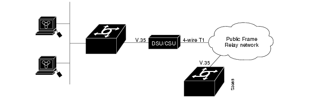
The CSU/DSU converts V.35 or RS-449 signals to the properly coded T1 transmission signal for successful reception by the Frame Relay network. Figure 9-1 illustrates the connections between the different components.
Figure 9-1 Typical Frame Relay Configuration
The Frame Relay interface actually consists of one physical connection between the network server and the switch that provides the service. This single physical connection provides direct connectivity to each device on a network, such as a StrataCom FastPacket wide-area network.
Frame Relay Configuration Task List
You must follow certain basic steps to enable Frame Relay for your network. In addition, you can customize Frame Relay for your particular network needs, set local and multicast DLCIs in test environments, and monitor Frame Relay connections. The first three tasks in the following list are required.
•
•
•
•
The following sections describe these tasks. See the examples at the end of this chapter for ideas of how to configure Frame Relay on your network. See the "Frame Relay Commands" chapter in the Access and Communication Servers Command Reference publication for information about the commands listed in the tasks.
Enable Frame Relay Encapsulation
To set Frame Relay encapsulation at the interface level, perform the following tasks beginning in global configuration mode:
Specify the serial interface, and enter interface configuration mode.
interface serial number1
Enable Frame Relay and specify the encapsulation method.
encapsulation frame-relay [ietf]
1 This command is documented in the "Interface Commands" chapter of the Access and Communication Servers Command Reference publication.
Frame Relay supports encapsulation of all supported protocols except bridging in conformance with RFC 1294, allowing interoperability between multiple vendors. Use the IETF form of Frame Relay encapsulation if your access server is connected to another vendor's equipment across a Frame Relay network. IETF encapsulation is supported at either the interface level or on a per-DLCI (map entry) basis.
For an example of how to enable Frame Relay and set the encapsulation method, see the sections "IETF Encapsulation Example" and "Static Address Mapping Examples" later in this chapter.
Configure Dynamic or Static Address Mapping
Dynamic address mapping uses Frame Relay Inverse ARP to request the next-hop protocol address for a specific connection, given its known DLCI. Responses to Inverse ARP requests are entered in an address-to-DLCI mapping table on the access server; the table is then used to supply the next-hop protocol address or the DLCI for outgoing traffic.
Inverse ARP is enabled by default for all protocols it supports, but can be disabled for specific protocol-DLCI pairs. As a result, you can use dynamic mapping for some protocols and static mapping for other protocols on the same DLCI. You can explicitly disable Inverse ARP for a protocol-DLCI pair if you know the protocol is not supported on the other end of the connection. See the "Disable or Reenable Frame Relay Inverse ARP" section later in this chapter for more information.
Configure Dynamic Mapping
Because Inverse ARP is enabled by default for all protocols that it supports, no additional command is required to configure dynamic mapping on an interface.
Configure Static Mapping
A static map links a specified next-hop protocol address to a specified DLCI. Static mapping removes the need for Inverse ARP requests; when you supply a static map, Inverse ARP is automatically disabled for the specified protocol on the specified DLCI.
You must use static mapping if the access server at the other end either does not support Inverse ARP at all or does not support Inverse ARP for a specific protocol that you want to use over Frame Relay.
To establish static mapping according to your network needs, perform one of the following tasks in interface configuration mode:
Define the mapping between a next-hop protocol address and the DLCI used to connect to the address.
frame-relay map protocol protocol-address dlci [broadcast] [ietf] [cisco]
The supported protocols and the corresponding keywords to enable them are as follows:
•
•
•
You can greatly simplify the configuration for the Open Shortest Path First (OSPF) protocol by adding the optional broadcast keyword when doing this task. See the frame-relay map description in the Access and Communication Servers Command Reference publication and the examples at the end of this chapter for more information about using the broadcast keyword.
For examples of how to establish static address mapping, see the "Static Address Mapping Examples" section later in this chapter.
Configure the LMI
Our Frame Relay software supports the industry-accepted standards for addressing the Local Management Interface (LMI), including the Cisco specification. To configure the LMI, complete the tasks in the following sections. The tasks in the first two sections are required.
•
•
Set the LMI Type
If the access server is attached to a public data network, the LMI type must match the type used on the public network. Otherwise, you can select an LMI type to suit the needs of your private Frame Relay network.
You can set one of three types of LMIs on our access server: ANSI T1.617 Annex D, Cisco, and ITU-T Q.933 Annex A. To do so, perform the following task in interface configuration mode:
The default LMI type is cisco.
For an example of how to set the LMI type, see the "Pure Frame Relay DCE Example" section later in this chapter.
Set the LMI Keepalive Interval
A keepalive interval must be set to enable the LMI. By default, this interval is ten seconds and, per the LMI protocol, must be less than the corresponding interval on the switch. To set the keepalive interval, perform the following task in interface configuration mode:
Set the keepalive interval.
frame-relay keepalive number
Turn off keepalives on networks without an LMI.
no frame-relay keepalive
This command has the same effect as the keepalive interface configuration command.
For an example of how to specify an LMI keepalive interval, see the "Two Access Servers in Static Mode Example" section later in this chapter.
Set the LMI Polling and Timer Intervals
You can set various optional counters, intervals, and thresholds to fine-tune the operation of your LMI DTE and DCE devices. Set these attributes by performing one or more of the following tasks in interface configuration mode:
See the "Frame Relay Commands" chapter in the Access and Communication Servers Command Reference publication for details about commands used to set the polling and timing intervals.
Customize Frame Relay for Your Network
Perform the tasks in the following sections to customize Frame Relay:
•
•
•
•
•
•
•
•
Configure Frame Relay Subinterfaces
To understand and define Frame Relay Subinterfaces, perform the tasks in the following sections:
•
•
After these tasks are completed, you can also perform the following optional task:
•
For an example of how to define a subinterface, see the section "Subinterface Examples" later in this chapter.
Understand and Define Frame Relay Subinterfaces
Frame Relay subinterfaces provide a mechanism for supporting partially meshed Frame Relay networks. Most protocols assume transitivity on a logical network; that is, if station A can talk to station B, and station B can talk to station C, then station A should be able to talk to station C directly. This is true on LANs, but is not true on Frame Relay networks unless A is directly connected to C. Additionally, certain protocols such as AppleTalk and transparent bridging could not be supported on partially meshed networks because they require "split horizon," in which a packet received on an interface cannot be transmitted out the same interface even if the packet is received and transmitted on different virtual circuits. By configuring Frame Relay subinterfaces, a single physical interface is treated as multiple virtual interfaces. This allows us to overcome split horizon rules. Packets received on one virtual interface can now be forwarded out another virtual interface, even if they are configured on the same physical interface.
Subinterfaces address these limitations by providing a way to subdivide a partially meshed Frame Relay network into a number of smaller, fully meshed (or point-to-point) subnetworks. Each subnetwork is assigned its own network number and appears to the protocols as if it is reachable through a separate interface. (Note that point-to-point subinterfaces can be unnumbered for use with IP, reducing the addressing burden that might otherwise result.)
For example, suppose you have a five-node Frame Relay network (see ) that is partially meshed (Network A). If the entire network is viewed as a single subnetwork (with a single network number assigned), most protocols assume that node A can transmit a packet directly to node E, when in fact it must be relayed through nodes C and D. This can be made to work with certain protocols (for example, IP) but will not work at all with other protocols (for example, AppleTalk) because nodes C and D will not relay the packet out the same interface on which it was received. One way to make this work fully is to create a fully meshed network (Network B), but that requires a large number of PVCs, which may not be economically feasible.
Using subinterfaces, the Frame Relay network can be subdivided into three smaller networks (Network C) with separate network numbers. Nodes A, B, and C are connected to a fully meshed network, and nodes C and D, as well as nodes D and E are connected via point-to-point networks. In this configuration, nodes C and D would see two subinterfaces, allowing them to forward packets without violating split horizon rules. I
Figure 9-2 Using Subinterfaces to Provide Full Connectivity on a Partially Meshed Frame Relay Network
Define Frame Relay Subinterfaces
To configure subinterfaces on a Frame Relay network, perform the following tasks:
Step 1
interface serial number1
Step 2
encapsulation frame-relay
Step 3
interface serial number.subinterface-number [multipoint | point-to-point]1
1 This command is documented in the "Interface Commands" chapter of the Access and Communication Servers Command Reference publication.
Subinterfaces can be configured for multipoint or point-to-point communication. Multipoint is the default.
Define Subinterface Addressing
For point-to-point subinterfaces, the destination is presumed to be known and is identified or implied in the frame-relay interface-dlci command. For multipoint subinterfaces, the destinations can be dynamically resolved through the use of Frame Relay Inverse ARP or can be statically mapped through the use of the frame-relay map command.
Addressing on Point-to-Point Subinterfaces
If you specified a point-to-point subinterface in Step 3 (above), perform the following task in interface configuration mode:
Associate the selected point-to-point subinterface with a DLCI.
frame-relay interface-dlci dlci [option]
For an explanation of the many available options, refer to this command in the Router Products Command Reference publication. For an example of how to associate a DLCI with a subinterface, see the section "Subinterface Examples" later in this chapter.
If you define a subinterface for point-to-point communication, you cannot reassign the same subinterface number to be used for multipoint communication without first rebooting the router. Instead, you can simply avoid using that subinterface number and use a different subinterface number instead.
Addressing on Multipoint Subinterfaces
If you specified a multipoint subinterface in Step 3 (above), perform the tasks in one or both of the following sections:
•
•
You can configure some protocols for dynamic address mapping and others for static address mapping.
Accept Inverse ARP for Dynamic Address Mapping on Multipoint Subinterfaces
Dynamic address mapping uses Frame Relay Inverse ARP to request the next-hop protocol address for a specific connection, given a DLCI. Responses to Inverse ARP requests are entered in an address-to-DLCI mapping table on the router; the table is then used to supply the next-hop protocol address or the DLCI for outgoing traffic.
Since the physical interface is now configured as multiple subinterfaces, you must provide information that distinguishes a subinterface from the physical interface and associates a specific subinterface with a specific DLCI.
To associate a specific multipoint subinterface with a specific DLCI, perform the following task in interface configuration mode:
Associate a specified multipoint subinterface with a DLCI.
frame-relay interface-dlci dlci
Inverse ARP is enabled by default for all protocols it supports, but can be disabled for specific protocol-DLCI pairs. As a result, you can use dynamic mapping for some protocols and static mapping for other protocols on the same DLCI. You can explicitly disable Inverse ARP for a protocol-DLCI pair if you know the protocol is not supported on the other end of the connection. See the "Disable or Reenable Frame Relay Inverse ARP" section later in this chapter for more information.
Because Inverse ARP is enabled by default for all protocols that it supports, no additional command is required to configure dynamic address mapping on a subinterface.
For an example of configuring Frame Relay multipoint subinterfaces with dynamic address mapping, see the " " section.
Configure Static Address Mapping on Multipoint Subinterfaces
A static map links a specified next-hop protocol address to a specified DLCI. Static mapping removes the need for Inverse ARP requests; when you supply a static map, Inverse ARP is automatically disabled for the specified protocol on the specified DLCI.
You must use static mapping if the router at the other end either does not support Inverse ARP at all or does not support Inverse ARP for a specific protocol that you want to use over Frame Relay.
To establish static mapping according to your network needs, perform one of the following tasks in interface configuration mode:
The supported protocols and the corresponding keywords to enable them are as follows:
•
•
•
The broadcast keyword is required for routing protocols such as OSI protocols and the Open Shortest Path First (OSPF) protocol. See the frame-relay map description in the Router Products Command Reference publication and the examples at the end of this chapter for more information about using the broadcast keyword.
For an example of how to establish static address mapping, see the sections "Two Access Servers in Static Mode Example," and "IPX Packet Access Server Example" later in this chapter.
Configure a Backup Interface for a Subinterface
Both point-to-point and multipoint Frame Relay subinterfaces can be configured with a backup interface. This allows individual PVCs to be backed up in case of failure rather than depending on the entire Frame Relay connection to fail before the backup takes over. You can configure a subinterface for backup on failure only, not for backup based on loading of the line.
If the serial interface has a backup interface, it will have precedence over the subinterface's backup interface in the case of complete loss of connectivity with the Frame Relay network. As a result, a subinterface backup is activated only if the serial interface is up, or if the serial interface is down and does not have a backup interface defined. If a subinterface has failed while its backup is in use, and then the serial interface goes down, the subinterface backup stays connected.
To configure a backup interface for a Frame Relay subinterface, perform the following tasks, beginning in global configuration mode:
Step 1
interface serial number1
Step 2
encapsulation frame-relay
Step 3
interface serial number.subinterface-number point-to-point1
Step 4
frame-relay interface-dlci dlci
Step 5
backup interface serial number1
Step 6
backup delay enable-delay disable-delay1
1 This command is documented in the "Interface Commands" chapter of the Access and Communication Servers Command Reference publication.
Configure Frame Relay Switching
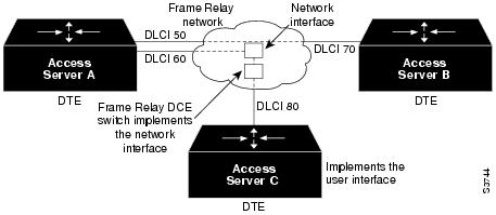
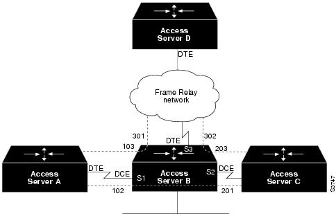
Frame Relay switching is a means of switching packets based upon the DLCI, which can be looked upon as the Frame Relay equivalent of a MAC address. The switching is performed by configuring your access server as a Frame Relay network. There are two parts to a Frame Relay network: a Frame Relay DTE (the access server) and a Frame Relay DCE switch. illustrates this concept.
Figure 9-3 Frame Relay Switched Network
In , access servers A, B, and C are Frame Relay DTEs connected to each other via a Frame Relay network. Our implementation of Frame Relay switching allows our access servers to be used as depicted in this Frame Relay network.
Perform the tasks in the following sections, as necessary, to configure Frame Relay switching:
•
•
•
These tasks are described in the following sections.
Enable Frame Relay Switching
You must enable packet switching before you can configure it on a Frame Relay DTE, DCE, or with Network to Network Interface (NNI) support. Do so by performing the following task in global configuration mode before configuring the switch type:
For an example of how to enable Frame Relay switching, see the switching examples later in this chapter.
Configure a Frame Relay DTE Device, DCE Switch, or NNI Support
You can configure an interface as a DTE device, DCE switch, or as a switch connected to a switch to support NNI connections. (DCE is the default.) To do so, perform the following task in interface configuration mode:
Configure a Frame Relay DTE device or DCE switch.
frame-relay intf-type [dce | dte | nni]
For an example of how to configure a DTE device or DCE switch, see the section "Hybrid DTE/DCE PVC Switching Example" later in this chapter.
For an example of how to configure NNI support, see the section "Pure Frame Relay DCE Example" later in this chapter.
Specify the Static Route
You must specify a static route for PVC switching. To do so, perform the following task in interface configuration mode:
Specify a static route for PVC switching.
frame-relay route in-dlci out-interface out-dlci
For an example of how to specify a static route, see the section "Pure Frame Relay DCE Example" later in this chapter.
Disable or Reenable Frame Relay Inverse ARP
Frame Relay Inverse ARP is a method of building dynamic address mappings in Frame Relay networks running AppleTalk, Banyan VINES, DECnet, IP, Novell IPX, and XNS. Inverse ARP allows the access server to discover the protocol address of a device associated with the virtual circuit.
Inverse ARP creates dynamic address mappings, as contrasted with the frame-relay map command, which defines static mappings between a specific protocol address and a specific DLCI (see the section "Configure Dynamic or Static Address Mapping" earlier in this chapter for more information).
Inverse ARP is enabled by default but can be disabled explicitly for a given protocol and DLCI pair. Disable or reenable Inverse ARP in the following conditions:
•
•
Note
You do not need to enable or disable Inverse ARP if you have a point-to-point interface, because there is only a single destination and discovery is not required.
To select Inverse ARP, perform the following task in interface configuration mode:
Create a Broadcast Queue for an Interface
Very large Frame Relay networks might have performance problems when a great many DLCIs terminate in a single access server and the access server must replicate access serving updates and service advertising updates on each DLCI. The updates can consume access-link bandwidth and cause significant latency variations in user traffic; the updates can also consume interface buffers and lead to higher packet rate loss for both user data and access serving updates.
To avoid such problems, you can create a special broadcast queue for an interface. The broadcast queue is managed independently of the normal interface queue, has its own buffers, and has a configurable size and service rate.
A broadcast queue is given a maximum transmission rate (throughput) limit measured in both bytes per second and packets per second. The queue is serviced to ensure that no more than this maximum is provided. The broadcast queue has priority when transmitting at a rate below the configured maximum, and hence has a guaranteed minimum bandwidth allocation. The two transmission rate limits are intended to avoid flooding the interface with broadcasts. The actual transmission rate limit in any second is the first of the two rate limits that is reached.
To create a broadcast queue, complete the following task in interface configuration mode:
Create a broadcast queue for an interface.
frame-relay broadcast-queue size byte-rate packet-rate
Configure Payload Compression
You can configure payload compression on point-to-point or multipoint interfaces or subinterfaces. Payload compression uses the stack method to predict what the next character in the frame will be. Because the prediction is done packet by packet, the dictionary is not conserved across packet boundaries.
Payload compression on each virtual circuit consumes approximately 40 KB for dictionary memory.
To configure payload compression on a specified multipoint interface or subinterface, complete the following task:
Enable payload compression on a multipoint interface.
frame-relay map protocol protocol-address dlci payload-compress packet-by-packet
To configure payload compression on a specified point-to-point interface or subinterface, complete the following task:
Enable payload compression on a point-to-point interface.
frame-relay payload-compress packet-by-packet
Configure TCP/IP Header Compression
TCP/IP header compression, as described by RFC 1144, is designed to improve the efficiency of bandwidth utilization over low-speed serial links. A typical TCP/IP packet includes a 40-byte datagram header. Once a connection is established, the header information is redundant and need not be repeated in every packet that is sent. By reconstructing a smaller header that identifies the connection and indicates the fields that changed and the amount of change, fewer bytes can be transmitted. The average compressed header is 10 bytes long.
For this algorithm to function, packets must arrive in order. If packets arrive out of order, the reconstruction will appear to create regular TCP/IP packets but the packets will not match the original. Because priority queuing changes the order in which packets are transmitted, enabling priority queueing on the interface is not recommended.
You can configure TCP/IP header compression in either of two ways, as described in the following sections:
•
•
The "Disable TCP/IP Header Compression" section describes how to disable this feature.
Note
Configure an Individual IP Map for TCP/IP Header Compression
TCP/IP header compression requires Cisco encapsulation. If you need to have IETF encapsulation on an interface as a whole, you can still configure a specific IP map to use Cisco encapsulation and TCP header compression.
In addition, even if you configure the interface to perform TCP/IP header compression, you can still configure a specific IP map not to compress TCP/IP headers.
You can specify whether TCP/IP header compression is active or passive. Active compression subjects every outgoing packet to TCP/IP header compression. Passive compression subjects an outgoing TCP/IP packet to header compression only if the packet had a compressed TCP/IP header when it was received.
To configure an IP map to use Cisco encapsulation and TCP/IP header compression, perform the following task in interface configuration mode:
Configure an IP map to use Cisco encapsulation and TCP/IP header compression.
frame-relay map ip-address dlci [broadcast] cisco tcp header-compression {active | passive}
The default encapsulation is cisco.
Note
For an example of how to configure TCP header compression on an IP map, see the "TCP Header Compression Examples" section later in this chapter.
Configure an Interface for TCP/IP Header Compression
You can configure the interface with active or passive TCP/IP header compression. Active compression, the default, subjects all outgoing TCP/IP packets to header compression. Passive compression subjects an outgoing packet to header compression only if the packet had a compressed TCP/IP header when it was received on that interface.
To apply TCP/IP header compression to an interface, you must perform the following tasks in interface configuration mode:
Configure Cisco encapsulation on the interface.
encapsulation frame-relay
Enable TCP/IP header compression on the interface.
frame-relay ip tcp header-compression [passive]
Note
For an example of how to configure TCP header compression on an interface, see the "TCP Header Compression Examples" section later in this chapter.
Disable TCP/IP Header Compression
You can disable TCP/IP header compression by using either of two commands that have different effects, depending on whether Frame Relay IP maps have been explicitly configured for TCP/IP header compression or have inherited their compression characteristics from the interface.
Frame Relay IP maps that have explicitly configured TCP/IP header compression must also have TCP/IP header compression explicitly disabled.
To disable TCP/IP header compression, perform one of the following tasks in interface configuration mode:
For an example of how to turn off TCP header compression, see the section "Turning Off TCP/IP Header Compression Examples."
Configure Discard Eligibility
You can specify which Frame Relay packets have low priority or low time sensitivity and will be the first to be dropped when a Frame Relay switch is congested. The mechanism that allows a Frame Relay switch to identify such packets is the discard eligibility (DE) bit.
This feature requires that the Frame Relay network be able to interpret the DE bit. Some networks take no action when the DE bit is set. Other networks use the DE bit to determine which packets to discard. The most desirable interpretation is to use the DE bit to determine which packets should be dropped first and also which packets have lower time sensitivity.
You can define DE lists that identify the characteristics of packets to be eligible for discarding, and you can also specify DE groups to identify the DLCI that is affected.
To define a DE list specifying the packets that can be dropped when the Frame Relay switch is congested, perform the following task in global configuration mode:
Define a DE list.
frame-relay de-list list-number {protocol protocol | interface type number} characteristic
You can specify DE lists based on the protocol or the interface, and on characteristics such as fragmentation of the packet, a specific TCP or UDP port, an access list number, or packet size. See the frame-relay de-list command for arguments and other information.
To define a DE group specifying the DE list and DLCI affected, perform the following task in interface configuration mode:
Configure DLCI Priority Levels
DLCI priority levels provide a traffic management tool for congestion problems caused by following situations:
•
•
DLCI priority levels provide a way to define multiple parallel DLCIs with different priorities for different types of traffic.
Before you configure the DLCI priority levels, complete the following tasks:
•
•
•
Make sure that you define each of the DLCIs to which you intend to apply priority levels. You can associate priority-level DLCIs with subinterfaces.
•
Note
To configure DLCI priority levels, perform the following task in interface configuration mode:
Note
Monitor the Frame Relay Connections
To monitor Frame Relay connections, perform any of the following tasks in EXEC mode:
Clear dynamically created Frame Relay maps, which are created by the use of inverse ARP.
clear frame-relay-inarp
Display information about Frame Relay DLCIs and the LMI.
show interfaces serial number1
Display LMI statistics.
show frame-relay lmi [type number]
Display the current Frame Relay map entries.
show frame-relay map
Display PVC statistics.
show frame-relay pvc [type number [dlci]]
Display configured static routes.
show frame-relay route
Display Frame Relay traffic statistics.
show frame-relay traffic
1 This command is documented in the "Interface Commands" chapter of the Router Products Command Reference publication.
Frame Relay Configuration Examples
This section provides examples of Frame Relay configurations. It includes the following examples:
•
•
•
•
•
•
•
•
IETF Encapsulation Example
The first example that follows sets IETF encapsulation at the interface level. The second example sets IETF encapsulation on a per-DLCI basis. In the first example, the keyword ietf sets the default encapsulation method for all maps to IETF.
encapsulation frame-relay IETFframe-relay map ip 172.30.123.2 48 broadcastframe-relay map ip 172.30.123.3 49 broadcastIn the following example, IETF encapsulation is configured on a per-DLCI basis. This configuration has the same result as the configuration in the first example.
encapsulation frame-relayframe-relay map ip 172.30.123.2 48 broadcast ietfframe-relay map ip 172.30.123.3 49 broadcast ietfStatic Address Mapping Examples
The following sections provide examples of static address mapping for the IP, AppleTalk, and IPX protocols.
Two Access Servers in Static Mode Example
The following examples illustrate how to configure two access servers for static mode.
Configuration for Access Server 1
interface serial 0!ip address 172.30.64.2 255.255.255.0encapsulation frame-relaykeepalive 10frame-relay map ip 172.30.64.1 43Configuration for Access Server 2
interface serial 0!ip address 172.30.64.1 255.255.255.0encapsulation frame-relaykeepalive 10frame-relay map ip 172.30.64.2 44AppleTalk Access Server Example
The following example illustrates how to configure two access servers to communicate with each other using AppleTalk over a Frame Relay network. Each access server has a Frame Relay static address map for the other access server. The use of the appletalk cable-range command indicates that this is extended AppleTalk (Phase II).
Configuration for Access Server 1
!interface Serial0ip address 172.21.59.24 255.255.255.0encapsulation frame-relayappletalk cable-range 10-20 18.47appletalk zone engframe-relay map appletalk 18.225 100 broadcastConfiguration for Access Server 2
!interface Serial2/3ip address 172.21.177.18 255.255.255.0encapsulation frame-relayappletalk cable-range 10-20 18.225appletalk zone engclockrate 2000000frame-relay map appletalk 18.47 100 broadcast!IPX Packet Access Server Example
The following example illustrates how to send packets destined for IPX address 200.0000.0c00.7b21 out on DLCI 102:
interface ethernet 0ipx network 2abc!interface serial 0ipx network 200encapsulation frame-relayframe-relay map ipx 200.0000.0c00.7b21 102 broadcastSubinterface Examples
The following sections provide basic Frame Relay subinterface examples and variations appropriate for different routed protocols and for bridging.
Basic Subinterface Examples
In the following example, subinterface 1 models a point-to-point subnet and subinterface 2 models a broadcast subnet. For emphasis, the multipoint keyword is used for serial subinterface 2, even though a subinterface is multipoint by default.
interface serial 0encapsulation frame-relayinterface serial 0.1 point-to-pointip address 10.0.1.1 255.255.255.0frame-relay interface-dlci 42interface serial 0.2 multipointip address 10.0.2.1 255.255.255.0frame-relay map 10.0.2.2 18IPX Routes over Frame Relay Subinterfaces Example
The following example configures a serial interface for Frame Relay encapsulation and sets up multiple IPX virtual networks corresponding to Frame Relay subinterfaces:
ipx access server 0000.0c02.5f4f!interface serial 0encapsulation frame-relayinterface serial 0.1 multipointipx network 1frame-relay map ipx 1.000.0c07.d530 200 broadcastipx network 2frame-relay map ipx 2.000.0c07.d530 300 broadcastFor subinterface serial 0.1, the access server at the other end might be configured as follows:
ipx access serverinterface serial 2 multipointipx network 1frame-relay map ipx 1.000.0c02.5f4f 200 broadcastUnnumbered IP over a Point-to-Point Subinterface Example
The following example sets up unnumbered IP over subinterfaces at both ends of a point-to-point connection. In this example, Access Server A functions as the DTE, and Access Server B functions as the DCE. Access Servers A and B are both attached to Token Ring networks.
Configuration for Access Server A
frame-relay switching!interface token-ring 0ip address 172.30.177.1 255.255.255.0!interface serial 0no ip addressencapsulation frame-relay IETF!interface Serial0.2 point-to-pointip unnumbered TokenRing0ip pim sparse-modeframe-relay interface-dlci 20Configuration for Access Server B
frame-relay switching!interface token-ring 0ip address 172.30.178.1 255.255.255.0!interface serial 0no ip addressencapsulation frame-relay IETFbandwidth 384clockrate 4000000frame-relay intf-type dce!interface serial 0.2 point-to-pointip unnumbered TokenRing1ip pim sparse-modebandwidth 384frame-relay interface-dlci 20Configuration Providing Backward Compatibility Example
The following configuration provides backward compatibility and interoperability. Creating this configuration is possible because of the flexibility provided by separately defining each map entry.
encapsulation frame-relayframe-relay map ip 172.30.123.2 48 broadcast ietf! interoperability is provided by IETF encapsulationframe-relay map ip 172.30.123.3 49 broadcast ietfframe-relay map ip 172.30.123.7 58 broadcast! this line allows the access server to connect with a ! device running an older version of softwareframe-relay map DECNET 21.7 49 broadcastConfigure IETF based on map entries and protocol for more flexibility. Use this method of configuration for backward compatibility and interoperability.
Booting from a Network Server over Frame Relay Example
When booting from a network server (netbooting) over Frame Relay, you cannot netboot via a broadcast. You must netboot from a specific host. Also, a frame-relay map command must exist for the host providing the netboot.
For example, if file igs3-bfx is to be booted from a host with IP address 172.30.126.2, the following commands need to be in the configuration:
boot system igs3-bfx 172.30.126.2interface Serial 0encapsulation frame-relayframe-relay map IP 172.30.126.2 100 broadcastThe frame-relay map command is used to map an IP address into a DLCI address. In order to netboot over Frame Relay, the address of the machine providing the netboot must be given explicitly, and a frame-relay map entry must exist for that site. For example:
boot system igs3-bfx.83-2.0 172.30.13.111!interface Serial 1ip address 172.30.126.200 255.255.255.0encapsulation frame-relay!frame-relay map IP 172.30.126.111 100 broadcastIn this case, 100 is the DLCI of the remote access server that can get to host 172.30.126.111.
The remote access server must have the following frame-relay map entry:
frame-relay map IP 172.30.126.200 101 broadcastThis entry allows the remote access server to return a boot image (from the netboot host) to the access server netbooting over Frame Relay. Here, 101 is the DLCI of the access server being netbooted.
Frame Relay Switching Examples
The following sections provide several examples of configuring one or more access servers as Frame Relay switches:
•
•
•
PVC Switching Configuration Example
You can configure your access server as a dedicated, DCE-only Frame Relay switch. Switching is based on DLCIs. The incoming DLCI is examined, and the outgoing interface and DLCI are determined. Switching takes place when the incoming DLCI in the packet is replaced by the outgoing DLCI, and the packet is sent out the outgoing interface.
In the following example, the access server switches two PVCs between interface serial 1 and 2. Frames with DLCI 100 received on serial 1 will be transmitted with DLCI 200 on serial 2 (see ).
Figure 9-4 PVC Switching Configuration
Configuration for Access Server A
frame-relay switching!interface Ethernet0ip address 172.30.160.58 255.255.255.0!interface Serial1no ip addressencapsulation frame-relaykeepalive 15frame-relay lmi-type ansiframe-relay intf-type dceframe-relay route 100 interface Serial2 200frame-relay route 101 interface Serial2 201clockrate 2000000!interface Serial2encapsulation frame-relaykeepalive 15frame-relay intf-type dceframe-relay route 200 interface Serial1 100frame-relay route 201 interface Serial1 101clockrate 64000Pure Frame Relay DCE Example
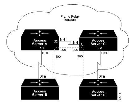
Using the PVC switching feature, it is possible to build an entire Frame Relay network using our access servers. In the following example, Access Server A and Access Server C act as Frame Relay switches implementing a two-node network. The standard Network to Network Interface (NNI) signaling protocol is used between Access Server A and Access Server C (see ).
Figure 9-5 Frame Relay DCE Configuration
Configuration for Access Server A
frame-relay switching!interface ethernet 0no ip addressshutdown!interface ethernet 1no ip addressshutdowninterface ethernet 2no ip addressshutdown!interface ethernet 3no ip addressshutdown!interface serial 0ip address 172.30.178.48 255.255.255.0shutdown!interface serial 1no ip addressencapsulation frame-relayframe-relay intf-type dceframe-relay lmi-type ansiframe-relay route 100 interface serial 2 200!interface serial 2no ip addressencapsulation frame-relayframe-relay intf-type nniframe-relay lmi-type q933aframe-relay route 200 interface serial 1 100clockrate 2048000!interface serial 3no ip addressshutdownConfiguration for Access Server C
frame-relay switching!interface ethernet 0no ip addressshutdown!interface ethernet1no ip addressshutdown!interface ethernet 2no ip addressshutdown!interface ethernet 3no ip addressshutdown!interface serial 0ip address 172.30.187.84 255.255.255.0shutdown!interface serial 1no ip addressencapsulation frame-relayframe-relay intf-type dceframe-relay route 300 interface serial 2 200!interface serial 2no ip addressencapsulation frame-relayframe-relay intf-type nniframe-relay lmi-type q933aframe-relay route 200 interface serial 1 300!interface serial 3no ip addressshutdownHybrid DTE/DCE PVC Switching Example
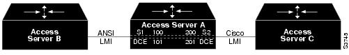
Access servers can also be configured as hybrid DTE/DCE Frame Relay switches (see ).
Figure 9-6 Hybrid DTE/DCE PVC Switching
In the following example, Access Server B acts as a hybrid DTE/DCE Frame Relay switch. It can switch frames between the two DCE ports and between a DCE port and a DTE port. Traffic from the Frame Relay network can also be terminated locally. In the example, three PVCs are defined, as follows:
Serial 1, DLCI 102 to serial 2, DLCI 201
:DCE switching
Serial 1, DLCI 103 to serial 3, DLCI 301
:DCE/DTE switching
Serial 2, DLCI 203 to serial 3, DLCI 302
:DCE/DTE switching
DLCI 400 is also defined for locally terminated traffic.
Configuration for Access Server B
frame-relay switching!interface ethernet 0ip address 172.30.123.231 255.255.255.0!interface ethernet 1ip address 172.30.5.231 255.255.255.0!interface serial 0no ip addressshutdown!interface serial 1no ip addressencapsulation frame-relayframe-relay intf-type dceframe-relay route 102 interface serial 2 201frame-relay route 103 interface serial 3 301!interface serial 2no ip addressencapsulation frame-relayframe-relay intf-type dceframe-relay route 201 interface serial 1 102frame-relay route 203 interface serial 3 302!interface serial 3ip address 172.30.111.231encapsulation frame-relayframe-relay lmi-type ansiframe-relay route 301 interface serial 1 103frame-relay route 302 interface serial 1 203frame-relay map ip 172.30.111.4 400 broadcastSwitching over an IP Tunnel Example
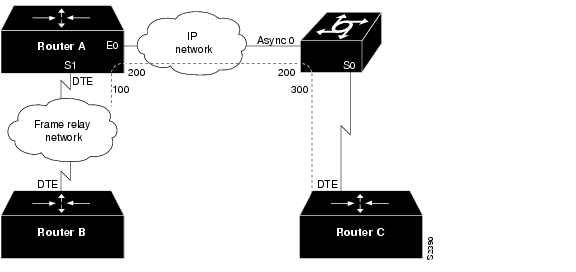
Switching over an IP tunnel is done by creating a point-to-point tunnel across the internetwork over which PVC switching can take place (see ).
Figure 9-7 Frame Relay Switch over IP Tunnel
The following configurations illustrate how to create the IP network depicted in .
Configuration for Access Server A
frame-relay switching!interface Ethernet0ip address 172.30.123.231 255.255.255.0!interface Serial0no ip addressshutdownip address 172.30.222.231 255.255.255.0encapsulation frame-relayframe-relay map ip 172.30.222.4 400 broadcastframe-relay route 100 interface Tunnel1 200!interface Tunnel1tunnel source Ethernet0tunnel destination 172.30.150.123Configuration for the Access Server
frame-relay switching!interface Async0ip address 172.30.231.123 255.255.255.0encapsulation ppp!interface Serial0ip address 172.30.150.123 255.255.255.0encapsulation ppp!interface Tunnel1tunnel source Async0tunnel destination 172.30.123.231!interface Serial1ip address 172.30.7.123 255.255.255.0encapsulation frame-relayframe-relay intf-type dceframe-relay route 300 interface Tunnel1 200TCP Header Compression Examples
These examples show various combinations of TCP/IP header compression and encapsulation characteristics on the interface and the effect on the inheritance of those characteristics on a Frame Relay IP map.
IP Map with Inherited TCP/IP Header Compression Example
The following example shows an interface configured for TCP/IP header compression and an IP map that inherits the compression characteristics. Note that the Frame Relay IP map is not explicitly configured for header compression.
interface serial 1encapsulation frame-relayip address 172.30.177.178 255.255.255.0frame-relay map ip 172.30.177.177 177 broadcastframe-relay ip tcp header-compression passiveUse of the show frame-relay map command will display the resulting compression and encapsulation characteristics; the IP map has inherited passive TCP/IP header compression:
access server> show frame-relay mapSerial 1 (administratively down): ip 172.30.177.177dlci 177 (0xB1,0x2C10), static,broadcast,CISCOTCP/IP Header Compression (inherited), passive (inherited)This example also applies to dynamic mappings achieved with the use of inverse-arp on point-to-point subinterfaces where no Frame Relay maps are configured.
Using an IP Map Not to Support TCP/IP Compression Example
The following example shows the use of a Frame Relay IP map to override the compression set on the interface:
interface serial 1encapsulation frame-relayip address 172.30.177.178 255.255.255.0frame-relay map ip 172.30.177.177 177 broadcast nocompressframe-relay ip tcp header-compression passiveUse of the show frame-relay map command will display the resulting compression and encapsulation characteristics; the IP map has not inherited TCP header compression:
Serial 1 (administratively down): ip 172.30.177.177dlci 177 (0xB1,0x2C10), static,broadcast,CISCOTurning Off TCP/IP Header Compression Examples
The following examples show the use of two different commands to turn off TCP/IP header compression.
Turning Off Inherited TCP/IP Header Compression Example
In the first example, the initial configuration is the following:
interface serial 1encapsulation frame-relayip address 172.30.177.179 255.255.255.0frame-relay ip tcp header-compression passiveframe-relay map ip 172.30.177.177 177 broadcastframe-relay map ip 172.30.177.178 178 broadcast tcp header-compressionYou enter the following commands interactively:
serial interface 1no frame-relay ip tcp header-compressionAs a result, header compression is turned off for the first map (with DLCI 177), which inherited its header compression characteristics from the interface, but not turned off for the second map (DLCI 178), which is explicitly configured for header compression.
Turning Off Explicit TCP/IP Header Compression Example
In the second example, the initial configuration is the same, but you enter the following commands interactively:
serial interface 1no frame-relay ip tcp header-compressionframe-relay map ip 172.30.177.178 178 nocompressThe result of the interactive commands is to turn off header compression for the first map (with DLCI 177), which inherited its header compression characteristics from the interface, and also explicitly to turn off header compression for the second map (with DLCI 178), which had been explicitly configured for header compression.