
 Feedback
Contents
- Transparent Tunneling of QSIG and Q.931
- Finding Feature Information
- Prerequisites for Transparent Tunneling of QSIG and Q.931
- Restrictions for Transparent Tunneling of QSIG and Q.931
- Information About Transparent Tunneling of QSIG or Q.931
- Use of the QSIG or Q.931 Protocols
- Purpose of Tunneling QSIG or Q.931 over SIP
- Encapsulation of QSIG in SIP Messaging
- Mapping of QSIG Message Elements to SIP Message Elements
- How to Transparently Tunnel QSIG over SIP
- Configuring Signaling Forward Settings for a Gateway
- Signaling Forward Settings for a Gateway
- Configuring Signaling Forward Settings for an Interface
- Signaling Forward Settings for an Interface
- Configuration Examples for Transparent Tunneling of QSIG
- Tunneling QSIG Raw Messages over SIP Example
- Tunneling QSIG Messages Unconditionally over SIP Example
- Tunneling QSIG Raw Messages over SIP on an Interface Example
- Tunneling QSIG Messages Unconditionally over SIP on an Interface Example
- Feature Information for Transparent Tunneling of QSIG and Q.931
Transparent Tunneling of QSIG and Q.931
Transparent Tunneling of QSIG and Q.931 over Session Initiation Protocol (SIP) Time-Division Multiplexing (TDM) Gateway and SIP-to-SIP Cisco Unified Border Element (Enterprise) was first introduced on Cisco IOS SIP gateways in phases. In the first phase, the Transparent Tunneling of QSIG over SIP TDM Gateway feature added the ability to transparently tunnel Q-signaling (QSIG) protocol ISDN messages across the Session Initiation Protocol (SIP) trunk. With this feature, QSIG messages (supplementary services carried within Q.931 FACILITY-based messages) can be passed end to end across a SIP network. However, in Cisco IOS Release 12.4(15)XY, deployment of this feature is limited to QSIG messages over SIP TDM gateways. In later releases, the ISDN Q.931 Tunneling over SIP TDM Gateway feature adds support for transparent tunneling of all Q.931 messages over SIP and for the Transparent Tunneling of QSIG and Q.931 over a SIP-SIP Cisco Unified Border Element.
Transparent tunneling is accomplished by encapsulating QSIG or Q.931 messages within SIP message bodies. These messages are encapsulated using "application/qsig" or "application/x-q931" Multipurpose Internet Mail Extensions (MIME) to tunnel between SIP endpoints. Using MIME to tunnel through Cisco SIP messaging does not include any additional QSIG/Q.931 services to SIP interworking.
Beginning with Cisco IOS XE Release 3.1S, support for this feature is expanded to include the Cisco ASR 1000 Series Router.
- Finding Feature Information
- Prerequisites for Transparent Tunneling of QSIG and Q.931
- Restrictions for Transparent Tunneling of QSIG and Q.931
- Information About Transparent Tunneling of QSIG or Q.931
- How to Transparently Tunnel QSIG over SIP
- Configuration Examples for Transparent Tunneling of QSIG
- Feature Information for Transparent Tunneling of QSIG and Q.931
Finding Feature Information
Your software release may not support all the features documented in this module. For the latest feature information and caveats, see the release notes for your platform and software release. To find information about the features documented in this module, and to see a list of the releases in which each feature is supported, see the Feature Information Table at the end of this document.
Use Cisco Feature Navigator to find information about platform support and Cisco software image support. To access Cisco Feature Navigator, go to www.cisco.com/go/cfn. An account on Cisco.com is not required.
Prerequisites for Transparent Tunneling of QSIG and Q.931
- Before configuring transparent tunneling of QSIG and Q.931 over a SIP trunk, verify the SIP configuration within the VoIP network for the appropriate originating and terminating gateways.
Cisco Unified Border Element
- Cisco IOS Release 12.4(15)XZ or a later release must be installed and running on your Cisco Unified Border Element.
- The Transparent Tunneling of QSIG over SIP TDM Gateway feature is intended for TDM PBX toll bypass and call center applications. In its first release (Cisco IOS Release 12.4(15)XY), only tunneling of QSIG messages is supported and only on TDM gateways. From Cisco IOS release 12.4(15)XZ and 12.4(20)T onward, support is added for the ISDN Q.931 Tunneling over SIP TDM Gateway and Transparent Tunneling of QSIG and Q.931 over SIP-SIP Cisco Unified Border Element.
Restrictions for Transparent Tunneling of QSIG and Q.931
- Transparent tunneling of QSIG or Q.931 does not function unless both the originating gateway (OGW) and the terminating gateway (TGW) are configured using the same ISDN switch type.
- This function is supported only on SIP-to-SIP configurations on Cisco Unified Border Element. Tunneling of QSIG or Q.931 is not supported on SIP-to-H.323 or H.323-to-H.323 configurations on Cisco Unified Border Element.
Information About Transparent Tunneling of QSIG or Q.931
- Use of the QSIG or Q.931 Protocols
- Purpose of Tunneling QSIG or Q.931 over SIP
- Encapsulation of QSIG in SIP Messaging
- Mapping of QSIG Message Elements to SIP Message Elements
Use of the QSIG or Q.931 Protocols
Q-series documents, controlled by the International Telecommunication Union (ITU), define the network Layer. The Q.931 document defines the Layer 3 protocol that serves as the connection control protocol for ISDN signaling--it is used primarily to manage the initiation, maintenance, and termination of connections over a digital network.
The Q signaling (QSIG) protocol is based on the Q.931 standard and is used for ISDN communications in a Private Integrated Services Network (PISN). The QSIG protocol makes it possible to pass calls from one circuit switched network, such as a PBX or private integrated services network exchange (PINX), to another. QSIG messages are, essentially, a subset of Q.931 messages that ensure the essential Q.931 FACILITY-based functions successfully traverse the network regardless of the various hardware involved.
Q.931 tunneling over Cisco IOS SIP gateways was introduced as the ability to transparently tunnel only QSIG messages--the FACILITY-based Q.931 messages. Beginning with Cisco IOS Release 12.4(15)XZ and Cisco IOS Release 12.4(20)T, tunneling of all Q.931 messages (SETUP, ALERTING, CONNECT, and RELEASE COMPLETE messages in addition to FACILITY-based messages) is supported on Cisco IOS SIP gateways. However, for clarity, the descriptions and examples in this document focus primarily on QSIG messages.
Purpose of Tunneling QSIG or Q.931 over SIP
TDM Gateways
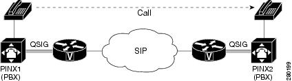
Transparently tunneling QSIG or Q.931 messages over SIP through SIP TDM gateways allows calls from one PINX to another to be passed through a SIP-based IP network with the equivalent functionality of passing through an H.323 network--without losing the functionality of the QSIG or Q.931 protocol to establish the call. To do this, QSIG or Q.931 messages are encapsulated within SIP messages (see the figure below).
Encapsulation of QSIG in SIP Messaging
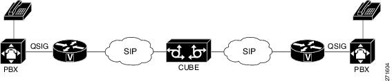
QSIG messages are tunneled by encapsulating them as a MIME body in a SIP INVITE message on the OGW. Then, the MIME body is extracted from the SIP message by the TGW at the other end of the SIP network. To tunnel QSIG messages to a TGW on another network, configure and use a SIP-to-SIP Cisco Unified Border Element connection between each network over which the SIP INVITE must travel to reach the TGW. This tunneling process helps preserve all QSIG capabilities associated with a call or call-independent signal as it travels to its destination.
The following events make it possible to tunnel QSIG messaging across a SIP network:
- The ingress gateway (OGW) receives a QSIG call (or signal) establishment request (a SETUP message) and generates a corresponding SIP INVITE request.
-
A corresponding SIP INVITE message is created and will contain the following:
- A Request-URI--message part containing a destination derived from the called party number information element (IE) in the QSIG SETUP message. The destination can be the egress (TGW or the Cisco Unified Border Element) for exiting the SIP network or it can be the required destination, leaving SIP proxies to determine which gateway will be used.
- A From header--message header containing a uniform resource identifier (URI) for either the OGW or calling party itself.
- A Session Description Protocol (SDP) offer--a message part proposing two media streams, one for each direction.
- A Multipart-MIME body--message part containing the tunneled QSIG data.
-
In addition to normal user agent (UA) handling of a SIP response, the OGW performs a corresponding action when it receives a SIP response, as follows:
- OGW receives 18x response with tunneled content--identifies the QSIG message (FACILITY, ALERTING, or PROGRESS) and sends a corresponding ISDN message.
- OGW receives 3xx , 4xx , 5xx , or 6xx final response--attempts alternative action to route the initial QSIG message or clears the call or signal using an appropriate QSIG cause value (DISCONNECT, RELEASE, or RELEASE COMPLETE). When the OGW receives a valid encapsulated QSIG RELEASE COMPLETE message, the OGW should use the cause value included in that QSIG message to determine the cause value.
 Note | You should expect a SIP 415 final response message (Unsupported Media Type) if the user agent server (UAS) is unable to process tunneled QSIG or Q.931 messages. |
-
- OGW receives a SIP 200 OK response--performs normal SIP processing, which includes sending an ACK message. Additionally, the OGW will encapsulate the QSIG message in the response to the PSTN side and will connect the QSIG user information channel to the appropriate media streams as called out in the SDP reply.
-
The TGW sends and the OGW receives a 200 OK response--the OGW sends an ACK message to the TGW and all successive messages during the session are encapsulated into the body of SIP INFO request messages. There are two exceptions:
- When a SIP connection requires an extended handshake process, renegotiation, or an update, the gateway may encapsulate a waiting QSIG message into a SIP re-INVITE or SIP UPDATE message during QSIG call establishment.
- When the session is terminated, gateways send a SIP BYE message. If the session is terminated by notice of a QSIG RELEASE COMPLETE message, that message can be encapsulated into the SIP BYE message.
How to Transparently Tunnel QSIG over SIP
To create a tunnel for QSIG messages across a SIP trunk, you must configure signaling forward settings on both the OGW and the TGW.
In the IP TDM gateway scenario, a gateway receives QSIG messages from PSTN and the ISDN module passes the raw QSIG message and, additionally, creates and includes a Generic Transparency Descriptor (GTD) that is passed with the raw QSIG message across the IP leg of the call.
In the SIP TDM gateway scenario, there are two options--raw message (rawmsg) and unconditional. The rawmsg option specifies tunneling of only raw message (application/qsig or application/x-q931). The unconditional option specifies tunneling of all additional message bodies, such as GTD and raw message (application/qsig or application/x-q931).
Use the signaling forwardcommand at the global configuration level to configure the feature for the entire gateway. You can also enable the QSIG tunneling feature for only a specific interface. If you enable this feature at both the global and dial peer configuration level and the option specified for the interface is different than for the gateway, the interface setting will override the global setting.
- Configuring Signaling Forward Settings for a Gateway
- Signaling Forward Settings for a Gateway
- Configuring Signaling Forward Settings for an Interface
- Signaling Forward Settings for an Interface
Configuring Signaling Forward Settings for a Gateway
To create a tunnel for QSIG messages across a SIP trunk using the same signaling forward setting for all interfaces on a gateway, configure the signaling forward settings in voice service voip configuration mode.
Signaling Forward Settings for a Gateway
The two options--raw messages (rawmsg) and unconditional--are mutually exclusive, which means you can specify only one option at the global configuration level. To enable and specify the signaling forward option, use the signaling forward command in voice service voip configuration mode.
Note | To override the global setting for a specific interface, use the signaling forward command at the dial-peer level (see the Configuring Signaling Forward Settings for an Interface). |
To create QSIG tunnels using the signaling forward configuration, configure both gateways. You can configure gateways globally or you can configure one or more interfaces on a gateway. In either case, you must include the recommended configuration for PRACK to avoid message/data loss.
You must also specify the central office switch type on the ISDN interface for both the OGW and the TGW. Use the isdn switch-type command in global or dial peer configuration mode to enable and specify the switch type for QSIG or Q.931 support.
Furthermore, before the isdn switch-type setting can function properly, you must assign network-side functionality for the primary-qsig switch type (either at the global or dial-peer level) using the isdn protocol-emulate command.
- signaling forward message-type
DETAILED STEPS
Configuring Signaling Forward Settings for an Interface
To create a tunnel for QSIG messages across a SIP trunk on a specific interface on a gateway, configure the signaling forward settings in dial peer configuration mode.
Signaling Forward Settings for an Interface
The two options--raw messages (rawmsg) and unconditional--are mutually exclusive, which means you can specify only one option per interface at the dial-peer level. To enable and specify the signaling forward option for an interface, use the signaling forward command in dial peer configuration mode.
Note | To set the signaling forward option for an entire gateway, use the signaling forward command at the global level (see the Feature Information for Transparent Tunneling of QSIG and Q.931). |
To create QSIG tunnels using the signaling forward configuration, configure at least one interface on both gateways. You can also configure all interfaces at once by configuring the gateway globally. In either case, you must include the recommended configuration for PRACK to avoid data loss.
You must also specify the central office switch type on the ISDN interface for both the OGW and the TGW. Use the isdn switch-type command in global or dial peer configuration mode to enable and specify the switch type for QSIG or Q.931 support.
Furthermore, before the isdn switch-type setting can function properly, you must assign network-side functionality for the primary-qsig switch type (either at the global or dial-peer level) using the isdn protocol-emulate command.
- signaling forward message-type
DETAILED STEPS
Configuration Examples for Transparent Tunneling of QSIG
- Tunneling QSIG Raw Messages over SIP Example
- Tunneling QSIG Messages Unconditionally over SIP Example
- Tunneling QSIG Raw Messages over SIP on an Interface Example
- Tunneling QSIG Messages Unconditionally over SIP on an Interface Example
Tunneling QSIG Raw Messages over SIP on an Interface Example
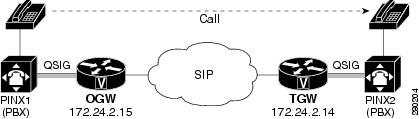
The following example shows how to configure transparent tunneling of only QSIG raw messages (application-qsig) on a gateway interface in a SIP network (see the figure below):
Tunneling QSIG Messages Unconditionally over SIP on an Interface Example
The following example shows how to configure transparent tunneling of QSIG messages unconditionally over a gateway interface in a SIP network (see the figure below):
Feature Information for Transparent Tunneling of QSIG and Q.931
The following table provides release information about the feature or features described in this module. This table lists only the software release that introduced support for a given feature in a given software release train. Unless noted otherwise, subsequent releases of that software release train also support that feature.
Use Cisco Feature Navigator to find information about platform support and Cisco software image support. To access Cisco Feature Navigator, go to www.cisco.com/go/cfn. An account on Cisco.com is not required.
History Table for the Cisco Unifired Border Element
| Table 1 | Feature Information for Transparent Tunneling of QSIG and Q.931 over SIP TDM Gateway and SIP-SIP Cisco Unified Border Element |
|
Feature Name |
Releases |
Feature Information |
|---|---|---|
|
Transparent Tunneling of QSIG and Q.931 over SIP TDM Gateway and SIP-SIP Cisco Unified Border Element |
12.4(15)XZ 12.4(20)T |
This feature adds support for transparent tunneling of all Q.931 messages over SIP and for the Transparent Tunneling of QSIG and Q.931 over a SIP-SIP Cisco Unified Border Element. Transparent tunneling is accomplished by encapsulating QSIG or Q.931 messages within SIP message bodies. These messages are encapsulated using "application/qsig" or "application/x-q931" Multipurpose Internet Mail Extensions (MIME) to tunnel between SIP endpoints. Using MIME to tunnel through Cisco SIP messaging does not include any additional QSIG/Q.931 services to SIP interworking. This feature uses no new or modified commands. |
History Table for the Cisco Unifired Border Element (Enterprise)
| Table 2 | Feature Information for Transparent Tunneling of QSIG and Q.931 over SIP TDM Gateway and SIP-SIP Cisco Unified Border Element |
|
Feature Name |
Releases |
Feature Information |
|---|---|---|
|
Transparent Tunneling of QSIG and Q.931 over SIP TDM Gateway and SIP-SIP Cisco Unified Border Element |
Cisco IOS XE Release 3.1S |
This feature adds support for transparent tunneling of all Q.931 messages over SIP and for the Transparent Tunneling of QSIG and Q.931 over a SIP-SIP Cisco Unified Border Element. Transparent tunneling is accomplished by encapsulating QSIG or Q.931 messages within SIP message bodies. These messages are encapsulated using "application/qsig" or "application/x-q931" Multipurpose Internet Mail Extensions (MIME) to tunnel between SIP endpoints. Using MIME to tunnel through Cisco SIP messaging does not include any additional QSIG/Q.931 services to SIP interworking. This feature uses no new or modified commands. |
Cisco and the Cisco logo are trademarks or registered trademarks of Cisco and/or its affiliates in the U.S. and other countries. To view a list of Cisco trademarks, go to this URL: www.cisco.com/go/trademarks. Third-party trademarks mentioned are the property of their respective owners. The use of the word partner does not imply a partnership relationship between Cisco and any other company. (1110R)
Any Internet Protocol (IP) addresses and phone numbers used in this document are not intended to be actual addresses and phone numbers. Any examples, command display output, network topology diagrams, and other figures included in the document are shown for illustrative purposes only. Any use of actual IP addresses or phone numbers in illustrative content is unintentional and coincidental.