
 Feedback
Contents
- Interchassis Asymmetric Routing Support for Zone-Based Policy Firewalls
- Finding Feature Information
- Restrictions for Interchassis Asymmetric Routing Support for Zone-Based Policy Firewalls
- Information About Interchassis Asymmetric Routing Support for Zone-Based Policy Firewalls
- Asymmetric Routing Overview
- Asymmetric Routing Support in Firewalls
- Active/Active Failover
- Active/Active Load-Sharing Application Redundancy
- Active/Standby Failover
- Asymmetric Routing in a WAN-LAN Topology
- Exclusive Virtual IP Addresses and Exclusive Virtual MAC Addresses
- Checkpoint Facility Support for Application Redundancy
- How to Configure Interchassis Asymmetric Routing Support for Zone-Based Policy Firewalls
- Configuring a Firewall
- Configuring a Redundancy Application Group and a Redundancy Group Protocol
- Configuring Data, Control, and Asymmetric Routing Interfaces
- Configuring a Redundant Interface Identifier and Asymmetric Routing on an Interface
- Configuration Examples for Interchassis Asymmetric Routing Support for Zone-Based Policy Firewalls
- Example: Configuring a Firewall
- Example: Configuring a Redundancy Application Group and a Redundancy Group Protocol
- Example: Configuring Data, Control, and Asymmetric Routing Interfaces
- Example: Configuring a Redundant Interface Identifier and Asymmetric Routing on an Interface
- Additional References
- Feature Information for Interchassis Asymmetric Routing Support for Zone-Based Policy Firewalls
Interchassis Asymmetric Routing Support for Zone-Based Policy Firewalls
The Interchassis Asymmetric Routing Support for Zone-Based Firewalls feature supports the forwarding of packets from a standby redundancy group to an active redundancy group for packet handling. If this feature is not enabled, the return TCP packets forwarded to the router that did not receive the initial synchronization (SYN) message are dropped because they do not belong to any known existing session. Interchassis asymmetric routing also supports active/active and active/standby load sharing redundancy.
This module provides an overview of asymmetric routing and active/active and active/standby load sharing redundancy, and describes how to configure asymmetric routing.
- Finding Feature Information
- Restrictions for Interchassis Asymmetric Routing Support for Zone-Based Policy Firewalls
- Information About Interchassis Asymmetric Routing Support for Zone-Based Policy Firewalls
- How to Configure Interchassis Asymmetric Routing Support for Zone-Based Policy Firewalls
- Configuration Examples for Interchassis Asymmetric Routing Support for Zone-Based Policy Firewalls
- Additional References
- Feature Information for Interchassis Asymmetric Routing Support for Zone-Based Policy Firewalls
Finding Feature Information
Your software release may not support all the features documented in this module. For the latest caveats and feature information, see Bug Search Tool and the release notes for your platform and software release. To find information about the features documented in this module, and to see a list of the releases in which each feature is supported, see the feature information table at the end of this module.
Use Cisco Feature Navigator to find information about platform support and Cisco software image support. To access Cisco Feature Navigator, go to www.cisco.com/go/cfn. An account on Cisco.com is not required.
Restrictions for Interchassis Asymmetric Routing Support for Zone-Based Policy Firewalls
Information About Interchassis Asymmetric Routing Support for Zone-Based Policy Firewalls
- Asymmetric Routing Overview
- Asymmetric Routing Support in Firewalls
- Active/Active Failover
- Active/Standby Failover
- Asymmetric Routing in a WAN-LAN Topology
- Exclusive Virtual IP Addresses and Exclusive Virtual MAC Addresses
- Checkpoint Facility Support for Application Redundancy
Asymmetric Routing Overview
Asymmetric routing occurs when packets from TCP or UDP connections flow in different directions through different routes. In asymmetric routing, packets that belong to a single TCP or UDP connection are forwarded through one interface in a redundancy group (RG), but returned through another interface in the same RG. In asymmetric routing, the packet flow remains in the same RG. When you configure asymmetric routing, packets received on the standby RG are redirected to the active RG for processing. If asymmetric routing is not configured, the packets received on the standby RG may be dropped.
Asymmetric routing determines the RG for a particular traffic flow. The state of the RG is critical in determining the handling of packets. If an RG is active, normal packet processing is performed. In case the RG is in a standby state and you have configured asymmetric routing and the asymmetric-routing always-divert enable command, packets are diverted to the active RG. Use the asymmetric-routing always-divert enable command to always divert packets received from the standby RG to the active RG.
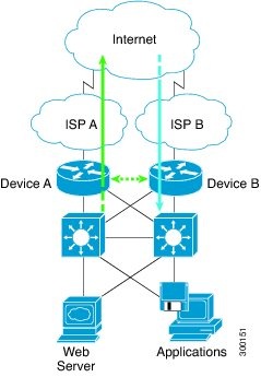
The figure below shows an asymmetric routing scenario with a separate asymmetric-routing interlink interface to divert packets to the active RG.
The following rules apply to asymmetric routing:
- 1:1 mapping exists between the redundancy interface identifier (RII) and the interface.
- 1:n mapping exists between the interface and an RG. (An interface can have multiple RGs.)
- 1:n mapping exists between an RG and applications that use it. (Multiple applications can use the same RG).
- 1:1 mapping exists between an RG and the traffic flow. The traffic flow must map only to a single RG. If a traffic flow maps to multiple RGs, an error occurs.
- RG = 0 for intrabox redundancy.
- 1:1 or 1:n mapping can exist between an RG and an asymmetric-routing interlink as long as the interlink has sufficient bandwidth to support all the RG interlink traffic.
Asymmetric routing consists of an interlink interface that handles all traffic that is to be diverted. The bandwidth of the asymmetric-routing interlink interface must be large enough to handle all expected traffic that is to be diverted. An IPv4 address must be configured on the asymmetric-routing interlink interface, and the IP address of the asymmetric routing interface must be reachable from this interface.
Asymmetric Routing Support in Firewalls
For intrabox asymmetric routing support, the firewall does a stateful Layer 3 and Layer 4 inspection of Internet Control Message Protocol (ICMP), TCP, and UDP packets. The firewall does a stateful inspection of TCP packets by verifying the window size and order of packets. The firewall also requires the state information from both directions of the traffic for stateful inspection. The firewall does a limited inspection of ICMP information flows. It verifies the sequence number associated with the ICMP echo request and response. The firewall does not synchronize any packet flows to the standby redundancy group (RG) until a session is established for that packet. An established session is a three-way handshake for TCP, the second packet for UDP, and informational messages for ICMP. All ICMP flows are sent to the active RG.
The firewall does a stateless verification of policies for packets that do not belong to the ICMP, TCP, and UDP protocols.
The firewall supports Layer 7 inspections through application-layer gateways (ALGs) or Application Inspection and Controls (AICs) that require a two-way traffic flow. The ALGs may create subflows or pinholes. A pinhole is a port that is opened through a firewall and that allows an application to gain controlled access to a protected network. The pinholes are not synchronized with the standby RG until they are established.
The firewall depends on bidirectional traffic to determine when a packet flow should be aged out and diverts all inspected packet flows to the active RG. Packet flows that have a pass policy and that include the same zone with no policy or a drop policy are not diverted.
When working with NAT, the firewall requires both the inside and outside NAT addresses. The classification of traffic is based on the outside global and inside local addresses and hence, NAT must divert all packet flows to the active RG before modifying any packets.
Active/Active Failover
In an active/active failover configuration, both devices can process network traffic. Active/active failover generates virtual MAC (VMAC) addresses for interfaces in each redundancy group (RG).
- The device that provides the running configuration to the failover pair when they start simultaneously.
- The device on which the failover RG appears in the active state when devices start simultaneously. Each failover RG in the configuration is configured with a primary or secondary device preference. You can configure both failover RGs to be in the active state on a single device and the standby failover RGs to be on the other device. You can also configure one failover RG to be in the active state and the other RG to be in the standby state on a single device.
Active/Active Load-Sharing Application Redundancy
The following figure shows two RGs, RG1 and RG2. The firewall is registered to both the groups. RG1 has a high priority on Router 1 and RG2 on Router 2. The firewall will process half of the sessions through RG1 on Router 1 and the other half through RG2 on Router 2. As a result, the firewall actively processes traffic on both routers.
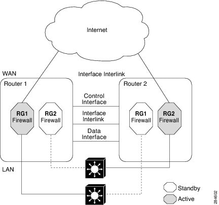
In an enterprise scenario, if all WAN links on Router 1 fail, switchover happens on Router 2. For example, if there is only one WAN link per box, the failure of the WAN link on the active RG triggers a failover. In the case of a hardware or software failure such as Cisco software reload, the standby will detect active groups on the failed router either through the hello packets timeout or through Bidirectional Forwarding Detection (BFD) if BFD is configured on the control interface.
When Router 1 goes down in the scenarios described, the standby RG will assume the active role on Router 2. When the RG changes the state from standby to active, the firewall will change the state of all sessions in the new active RG and will start processing the traffic.
Active/Standby Failover
Active/standby failover enables you to use a standby device to take over the functionality of a failed device. A failed active device changes to the standby state, and the standby device changes to the active state. The device that is now in the active state takes over IP addresses and MAC addresses of the failed device and starts processing traffic. The device that is now in the standby state takes over standby IP addresses and MAC addresses. Because network devices do not see any change in the MAC-to-IP address pairing, Address Resolution Protocol (ARP) entries do not change or time out anywhere on the network.
In an active/standby scenario, the main difference between two devices in a failover pair depends on which device is active and which device is a standby, namely which IP addresses to use and which device actively passes the traffic. The active device always becomes the active device if both devices start up at the same time (and are of equal operational health). MAC addresses of the active device are always paired with active IP addresses.
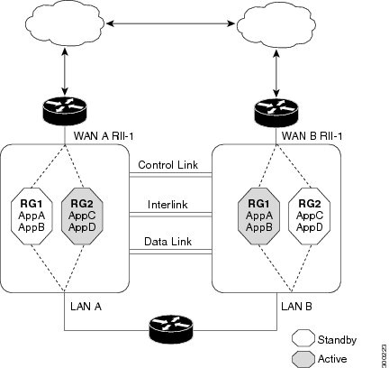
Asymmetric Routing in a WAN-LAN Topology
Exclusive Virtual IP Addresses and Exclusive Virtual MAC Addresses
Virtual IP (VIP) addresses and virtual MAC (VMAC) addresses are used by security applications to control interfaces that receive traffic. An interface is paired with another interface, and these interfaces are associated with the same redundancy group (RG). The interface that is associated with an active RG exclusively owns the VIP and VMAC. The Address Resolution Protocol (ARP) process on the active device sends ARP replies for any ARP request for the VIP, and the Ethernet controller for the interface is programmed to receive packets destined for the VMAC. When an RG failover occurs, the ownership of the VIP and VMAC changes. The interface that is associated with the newly active RG sends a gratuitous ARP and programs the interface's Ethernet controller to accept packets destined for the VMAC.
IPv6 Support
You can assign each redundancy group (RG) on a traffic interface for both IPv4 and IPv6 virtual IP (VIP) addresses under the same redundancy interface identifier (RII). Each RG uses a unique virtual MAC (VMAC) address per RII. For an RG, the IPv6 link-local VIP and global VIP coexist on an interface.
You can configure an IPv4 VIP, a link-local IPv6 VIP, and/or a global IPv6 VIP for each RG on a traffic interface. IPv6 link-local VIP is mainly used when configuring static or default routes, whereas IPv6 global VIP is widely used in both LAN and WAN topologies.
You must configure a physical IP address before configuring an IPv4 VIP.
Checkpoint Facility Support for Application Redundancy
Checkpointing is the process of storing the current state of a device and using that information during restart when the device fails. The checkpoint facility (CF) supports communication between peers by using the Inter-Process Communication (IPC) protocol and the IP-based Stream Control Transmission Protocol (SCTP). CF also provides an infrastructure for clients or devices to communicate with their peers in multiple domains. Devices can send checkpoint messages from the active to the standby device.
 Note | Domains in the same chassis cannot communicate with each other. |
How to Configure Interchassis Asymmetric Routing Support for Zone-Based Policy Firewalls
- Configuring a Firewall
- Configuring a Redundancy Application Group and a Redundancy Group Protocol
- Configuring Data, Control, and Asymmetric Routing Interfaces
- Configuring a Redundant Interface Identifier and Asymmetric Routing on an Interface
Configuring a Firewall
DETAILED STEPS
Configuring a Redundancy Application Group and a Redundancy Group Protocol
DETAILED STEPS
Configuring Data, Control, and Asymmetric Routing Interfaces
Note | Asymmetric routing, data, and control must be configured on separate interfaces. |
DETAILED STEPS
Configuring a Redundant Interface Identifier and Asymmetric Routing on an Interface
DETAILED STEPS
Configuration Examples for Interchassis Asymmetric Routing Support for Zone-Based Policy Firewalls
- Example: Configuring a Firewall
- Example: Configuring a Redundancy Application Group and a Redundancy Group Protocol
- Example: Configuring Data, Control, and Asymmetric Routing Interfaces
- Example: Configuring a Redundant Interface Identifier and Asymmetric Routing on an Interface
Example: Configuring a Firewall
Router# configure terminal
Router(config)# class-map type inspect match-any ddos-class
Router(config-cmap)# match protocol tcp
Router(config-cmap-c)# exit
Router(config)# parameter-map type inspect global
Router(config-profile)# redundancy
Router(config-profile)# exit
Router(config)# policy-map type inspect ddos-fw
Router(config-pmap)# class type inspect ddos-class
Router(config-pmap-c)# inspect
Router(config-pmap-c)# exit
Router(config-pmap)# class class-default
Router(config-pmap-c)# drop
Router(config-pmap-c)# exit
Router(config-pmap)# exit
Router(config)# zone security private
Router(config-sec-zone)# exit
Router(config)# zone security public
Router(config-sec-zone)# exit
Router(config)# zone-pair security private2public source private destination public
Router((config-sec-zone-pair)# service-policy type inspect ddos-fw
Router((config-sec-zone-pair)# exit
Router(config)# interface gigabitethernet 0/1/0.1
Router(config-subif)# ip address 10.1.1.1 255.255.255.0
Router(config-subif)# encapsulation dot1q 2
Router(config-subif)# zone-member security private
Router(config-subif)# exit
Router(config)# interface gigabitethernet 1/1/0.1
Router(config-subif)# ip address 10.2.2.2 255.255.255.0
Router(config-subif)# encapsulation dot1q 2
Router(config-subif)# zone-member security public
Router(config-subif)# end
Example: Configuring a Redundancy Application Group and a Redundancy Group Protocol
Device# configure terminal
Device(config)# redundancy
Device(config-red)# application redundancy
Device(config-red-app)# group 1
Device(config-red-app-grp)# name group1
Device(config-red-app-grp)# priority 100 failover threshold 50
Device(config-red-app-grp)# preempt
Device(config-red-app-grp)# track 50 decrement 50
Device(config-red-app-grp)# exit
Device(config-red-app)# protocol 1
Device(config-red-app-prtcl)# timers hellotime 3 holdtime 10
Device(config-red-app-prtcl)# authentication md5 key-string 0 n1 timeout 100
Device(config-red-app-prtcl)# bfd
Device(config-red-app-prtcl)# end
Example: Configuring Data, Control, and Asymmetric Routing Interfaces
Device# configure terminal
Device(config)# redundancy
Device(config-red)# application redundancy
Device(config-red-app)# group 1
Device(config-red-app-grp)# data GigabitEthernet 0/0/0
Device(config-red-app-grp)# control GigabitEthernet 0/0/2 protocol 1
Device(config-red-app-grp)# timers delay 100 reload 400
Device(config-red-app-grp)# asymmetric-routing interface GigabitEthernet 0/1/1
Device(config-red-app-grp)# asymmetric-routing always-divert enable
Device(config-red-app-grp)# end
Additional References
Technical Assistance
| Description | Link |
|---|---|
|
The Cisco Support and Documentation website provides online resources to download documentation, software, and tools. Use these resources to install and configure the software and to troubleshoot and resolve technical issues with Cisco products and technologies. Access to most tools on the Cisco Support and Documentation website requires a Cisco.com user ID and password. |
Feature Information for Interchassis Asymmetric Routing Support for Zone-Based Policy Firewalls
The following table provides release information about the feature or features described in this module. This table lists only the software release that introduced support for a given feature in a given software release train. Unless noted otherwise, subsequent releases of that software release train also support that feature.
Use Cisco Feature Navigator to find information about platform support and Cisco software image support. To access Cisco Feature Navigator, go to www.cisco.com/go/cfn. An account on Cisco.com is not required.
| Table 1 | Feature Information for Interchassis Asymmetric Routing Support for Zone-Based Policy Firewalls |
| Feature Name | Releases | Feature Information |
|---|---|---|
|
Interchassis Asymmetric Routing Support for Zone-Based Policy Firewalls |
15.2(3)T |
The Interchassis Asymmetric Routing Support for Zone-Based Policy Firewalls feature supports the forwarding of packets from a standby redundancy group to the active redundancy group for packet handling. The following commands were introduced or modified: asymmetric-routing, debug redundancy application group asymmetric-routing, redundancy asymmetric-routing enable, redundancy group (interface), redundancy rii, and show redundancy application asymmetric-routing. |
Cisco and the Cisco logo are trademarks or registered trademarks of Cisco and/or its affiliates in the U.S. and other countries. To view a list of Cisco trademarks, go to this URL: www.cisco.com/go/trademarks. Third-party trademarks mentioned are the property of their respective owners. The use of the word partner does not imply a partnership relationship between Cisco and any other company. (1110R)
Any Internet Protocol (IP) addresses and phone numbers used in this document are not intended to be actual addresses and phone numbers. Any examples, command display output, network topology diagrams, and other figures included in the document are shown for illustrative purposes only. Any use of actual IP addresses or phone numbers in illustrative content is unintentional and coincidental.