
 Feedback
Contents
- VRF-Aware Cisco Firewall
- Finding Feature Information
- Prerequisites for VRF-Aware Cisco Firewall
- Restrictions for VRF-Aware Cisco Firewall
- Information About VRF-Aware Cisco Firewall
- Cisco Firewall
- VRF
- VRF-lite
- Per-VRF URL Filtering
- AlertsandAuditTrails
- MPLS VPN
- VRF-aware NAT
- VRF-aware IPSec
- VRF Aware Cisco IOS Firewall Deployment
- Distributed Network Inclusion of VRF Aware Cisco IOS Firewall
- Hub-and-Spoke Network Inclusion of VRF Aware Cisco IOS Firewall
- How to Configure VRF-Aware Cisco Firewall
- Configuring and Checking ACLs to Ensure that Non-Firewall Traffic is Blocked
- Creating and Naming Firewall Rules and Applying the Rules to an Interface
- Identifying and Setting Firewall Attributes
- Verifying the VRF-Aware Cisco Firewall Configuration and Functioning
- Configuration Examples for VRF-Aware Cisco Firewall
- Additional References
- Feature Information for VRF-Aware Cisco Firewall
- Glossary
VRF-Aware Cisco Firewall
VRF-Aware Cisco Firewall applies Cisco Firewall functionality to Virtual Routing and Forwarding (VRF) interfaces when the firewall is configured on a service provider (SP) or large enterprise edge device. SPs can provide managed services to small and medium business markets.
The VRF-Aware Cisco Firewall supports VRF-aware URL filtering and VRF-lite (also known as Multi-VRF CE).
- Finding Feature Information
- Prerequisites for VRF-Aware Cisco Firewall
- Restrictions for VRF-Aware Cisco Firewall
- Information About VRF-Aware Cisco Firewall
- How to Configure VRF-Aware Cisco Firewall
- Configuration Examples for VRF-Aware Cisco Firewall
- Additional References
- Feature Information for VRF-Aware Cisco Firewall
- Glossary
Finding Feature Information
Your software release may not support all the features documented in this module. For the latest caveats and feature information, see Bug Search Tool and the release notes for your platform and software release. To find information about the features documented in this module, and to see a list of the releases in which each feature is supported, see the feature information table at the end of this module.
Use Cisco Feature Navigator to find information about platform support and Cisco software image support. To access Cisco Feature Navigator, go to www.cisco.com/go/cfn. An account on Cisco.com is not required.
Restrictions for VRF-Aware Cisco Firewall
- VRF-Aware Cisco Firewall is not supported on Multiprotocol Label Switching (MPLS) interfaces.
- If two VPN networks have overlapping addresses, VRF-aware network address translation (NAT) is required for them to support VRF-aware firewalls.
- When crypto tunnels belong to multiple VPNs terminate on a single interface, you cannot apply per-VRF firewall policies.
Information About VRF-Aware Cisco Firewall
- Cisco Firewall
- VRF
- VRF-lite
- Per-VRF URL Filtering
- AlertsandAuditTrails
- MPLS VPN
- VRF-aware NAT
- VRF-aware IPSec
- VRF Aware Cisco IOS Firewall Deployment
Cisco Firewall
Cisco firewall provides robust, integrated firewall and intrusion detection functionality for every perimeter of the network. Available for a wide range of Cisco software-based devices, Cisco firewall offers sophisticated security and policy enforcement for connections within an organization (intranet) and between partner networks (extranets), as well as for securing Internet connectivity for remote and branch offices.
Cisco firewall enhances existing Cisco security capabilities such as authentication, encryption, and failover, with state-of-the-art security features such as stateful, application-based filtering (context-based access control), defense against network attacks, per-user authentication and authorization, and real-time alerts.
Cisco firewall is configurable through Cisco ConfigMaker software, an easy-to-use Microsoft Windows 95, Windows 98, NT 4.0 based software tool.
Cisco firewall provides great value in addition to these benefits:
- Flexibility--Provides multiprotocol routing, perimeter security, intrusion detection, VPN functionality, and dynamic per-user authentication and authorization.
- Investment protection--Leverages existing multiprotocol device investment.
- Scalable deployment--Scales to meet bandwidth and performance requirements of any network.
- VPN support--Provides a complete VPN solution based on Cisco IPSec and other Cisco software-based technologies, including Layer 2 Tunneling Protocol (L2TP) tunneling and quality of service (QoS).
The VRF-aware Cisco firewall is different from the non-VRF-aware firewall because it does the following:
- Allows users to configure a per-VRF firewall. The firewall inspects IP packets that are sent and received within a VPN routing and forwarding (VRF).
- Allows service providers (SP) to deploy the firewall on the provider edge (PE) device.
- Supports overlapping IP address space, thereby allowing traffic from nonintersecting VRFs to have the same IP address.
- Supports per-VRF (not global) firewall command parameters and denial-of-service (DoS) parameters so that the VRF-aware firewall can run as multiple instances (with VRF instances) allocated to various VPN customers.
- Performs per-VRF URL filtering.
- Generates VRF-specific syslog messages that can be seen only by a particular VPN. These alerts and audit-trail messages allow network administrators to manage the firewall; that is, they can adjust firewall parameters, detect malicious sources and attacks, add security policies, and so forth. The VRF name is tagged to syslog messages being logged to the syslog server.
Both VRF-aware and non-VRF-aware firewalls now allow you to limit the number of firewall sessions. Otherwise, it would be difficult for VRFs to share device resources because one VRF may consume a maximum amount of resources, leaving few resources for other VRFs. That would cause the DoS to other VRFs. To limit the number of sessions, enter the ipinspectname command.
VRF
VPN Routing and Forwarding (VRF) is an IOS route table instance for connecting a set of sites to a VPN service. A VRF contains a template of a VPN Routing/Forwarding table in a PE router.
The overlapping addresses, usually resulting from the use of private IP addresses in customer networks, are one of the major obstacles to successful deployment of peer-to-peer VPN implementation. The MPLS VPN technology provides a solution to this dilemma.
Each VPN has its own routing and forwarding table in the router, so any customer or site that belongs to a VPN is provided access only to the set of routes contained within that table. Any PE router in the MPLS VPN network therefore contains a number of per-VPN routing tables and a global routing table that is used to reach other routers in the service provider network. Effectively, a number of virtual routers are created in a single physical router.
VRF-lite
VRF-lite is a feature that enables a service provider to support two or more VPNs, where IP addresses can be overlapped among the VPNs. VRF-lite uses input interfaces to distinguish routes for different VPNs and forms virtual packet-forwarding tables by associating one or more Layer 3 interfaces with each VRF. Interfaces in a VRF can be physical, such as Ethernet ports, or logical, such as VLAN switched virtual interfaces (SVIs). However, a Layer 3 interface cannot belong to more than one VRF at a time.
 Note | VRF-lite interfaces must be Layer 3 interfaces. |
VRF-lite includes these devices:
- Customer edge (CE) devices provide customer access to the service provider network over a data link to one or more provider edge (PE) routers. The CE device advertises the site's local routes to the PE router and learns the remote VPN routes from it. A Catalyst 4500 switch can be a CE.
- Provider edge (PE) routers exchange routing information with CE devices by using static routing or a routing protocol such as BGP, RIPv1, or RIPv2.
- Provider routers (or core routers) are any routers in the service provider network that do not attach to CE devices.
- The PE is only required to maintain VPN routes for those VPNs to which it is directly attached, eliminating the need for the PE to maintain all of the service provider VPN routes. Each PE router maintains a VRF for each of its directly connected sites. Multiple interfaces on a PE router can be associated with a single VRF if all of these sites participate in the same VPN. Each VPN is mapped to a specified VRF. After learning local VPN routes from CEs, a PE router exchanges VPN routing information with other PE routers by using internal BGP (IBPG).
With VRF-lite, multiple customers can share one CE, and only one physical link is used between the CE and the PE. The shared CE maintains separate VRF tables for each customer, and switches or routes packets for each customer based on its own routing table. VRF-lite extends limited PE functionality to a CE device, giving it the ability to maintain separate VRF tables to extend the privacy and security of a VPN to the branch office.
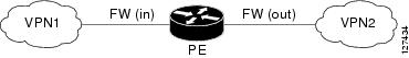
In a VRF-to-VRF situation, if firewall policies are applied on both inbound and outbound interfaces as shown in the figure below, the firewall on the inbound interface takes precedence over the firewall on the outbound interface. If the incoming packets do not match against the firewall rules (that is, the inspection protocols) configured on the inbound interface, the firewall rule on the outbound interface is applied to the packet.
Per-VRF URL Filtering
The VRF-aware firewall supports per-VRF URL filtering. Each VPN can have its own URL filter server. The URL filter server typically is placed in the shared service segment of the corresponding VPN. (Each VPN has a VLAN segment in the shared service network.) The URL filter server can also be placed at the customer site.
AlertsandAuditTrails
Context-based access control (CBAC) generates real-time alerts and audit trails based on events tracked by the firewall. Enhanced audit trail features use SYSLOG to track all network transactions; recording time stamps, the source host, the destination host, ports used, and the total number of transmitted bytes, for advanced, session-based reporting. Real-time alerts send SYSLOG error messages to central management consoles upon detecting suspicious activity. Using CBAC inspection rules, you can configure alerts and audit trail information on a per-application protocol basis. For example, if you want to generate audit trail information for HTTP traffic, you can specify that in the CBAC rule covering HTTP inspection.
MPLS VPN
The Multiprotocol Label Switching (MPLS) VPN Feature allows multiple sites to interconnect transparently through a service provider (SP)network. One SP network can support several IP VPNs. Each VPN appears to its users as a private network, separate from all other networks. Within a VPN, each site can send IP packets to any other site in the same VPN.
Each VPN is associated with one or more VPN routing and forwarding (VRF) instances. A VRF consists of an IP routing table, a derived Cisco Express Forwarding table, and a set of interfaces that use the forwarding table.
The device maintains a separate routing and Cisco Express Forwarding table for each VRF. This prevents information from being sent outside the VPN and allows the same subnet to be used in several VPNs without causing duplicate IP address problems.
The device using Multiprotocol BGP (MP-BGP) distributes the VPN routing information using the MP-BGP extended communities.
VRF-aware NAT
Network Address Translation (NAT) allows a single device, such as a router, to act as an agent between the Internet (or public network) and a local (or private) network. Although NAT systems can provide broad levels of security advantages, their main objective is to economize on address space.
NAT allows organizations to resolve the problem of IP address depletion when they have existing networks and need to access the Internet. Sites that do not yet possess NIC-registered IP addresses must acquire them. Cisco IOS NAT eliminates concern and bureaucratic delay by dynamically mapping thousands of hidden internal addresses to a range of easy-to-get addresses.
In general, a NAT system makes it more difficult for an attacker to determine the following:
- Number of systems running on a network
- Type of machines and operating systems they are running
- Network topology and arrangement
NAT integration with MPLS VPNs allows multiple MPLS VPNs to be configured on a single device to work together. NAT can differentiate which MPLS VPN it receives IP traffic from even if the MPLS VPNS are all using the same IP addressing scheme. This enables multiple MPLS VPN customers to share services while ensuring that each MPLS VPN is completely separate from the other.
MPLS service providers would like to provide value-added services such as Internet connectivity, domain name servers (DNS), and VoIP service to their customers. This requires that their customers IP addresses be different when reaching the services. Because MPLS VPN allows customers to use overlapped IP addresses in their networks, NAT must be implemented to make the services possible.
There are two approaches to implementing NAT in the MPLS VPN network. NAT can be implemented on the CE router, which is already supported by NAT, or it can be implemented on a PE router. The NAT Integration with MPLS VPNs feature enables the implementation of NAT on a PE router in an MPLS cloud.
VRF-aware IPSec
The VRF-aware IPSec feature maps an IP Security (IPSec) tunnel to an MPLS VPN. Using the VRF-aware IPSec feature, you can map IPSec tunnels to VRF instances using a single public-facing address.
Each IPSec tunnel is associated with two VRF domains. The outer encapsulated packet belongs to a VRF domain called the Front Door VRF (FVRF). The inner, protected IP packet belongs to a domain called the Inside VRF (IVRF). In other words, the local endpoint of the IPSec tunnel belongs to the FVRF, whereas the source and destination addresses of the inside packet belong to the IVRF.
One or more IPSec tunnels can terminate on a single interface. The FVRF of all these tunnels is the same and is set to the VRF that is configured on that interface. The IVRF of these tunnels can be different and depends on the VRF that is defined in the Internet Security Association and Key Management Protocol (ISAKMP) profile that is attached to a crypto map entry.
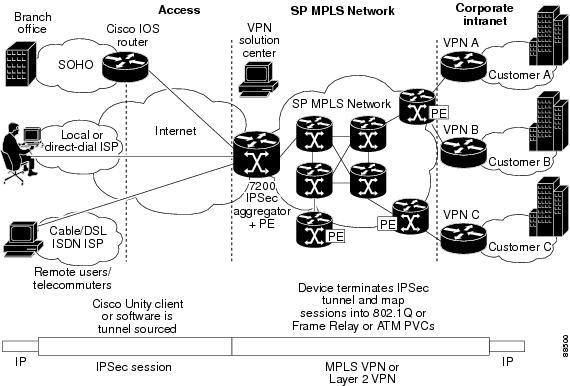
The figure below illustrates a scenario showing IPSec to MPLS and Layer 2 VPNs.
VRF Aware Cisco IOS Firewall Deployment
A firewall can be deployed at many points within the network to protect VPN sites from Shared Service (or the Internet) and vice versa. The following firewall deployments are described:
- Distributed Network Inclusion of VRF Aware Cisco IOS Firewall
- Hub-and-Spoke Network Inclusion of VRF Aware Cisco IOS Firewall
Distributed Network Inclusion of VRF Aware Cisco IOS Firewall
A VRF Aware Cisco IOS Firewall in a distributed network has the following advantages:
- The firewall is distributed across the MPLS core, so the firewall processing load is distributed to all ingress PE routers.
- VPN Firewall features can be deployed in the inbound direction.
- Shared Service is protected from the VPN site at the ingress PE router; therefore, malicious packets from VPN sites are filtered at the ingress PE router before they enter the MPLS core.
However, the following disadvantages exist:
- There is no centralized firewall deployment, which complicates the deployment and management of the firewall.
- Shared Service firewall features cannot be deployed in the inbound direction.
- The MPLS core is open to the Shared Service. Therefore, malicious packets from Shared Service are filtered only at the ingress PE router after traveling through all core routers.
The figure below illustrates a typical situation in which an SP offers firewall services to VPN customers VPN1 and VPN2, thereby protecting VPN sites from the external network (for example, Shared Services and the Internet) and vice versa.
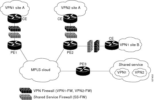
In this example, VPN1 has two sites, Site A and Site B, that span across the MPLS core. Site A is connected to PE1, and Site B is connected to PE2. VPN2 has only one site that is connected to PE2.
Each VPN (VPN1 and VPN2) has the following:
- A VLAN segment in the Shared Service that is connected to the corresponding VLAN subinterface on PE3.
- Internet access through the PE3 router that is connected to the Internet
A distributed network requires the following firewall policies:
- VPN Firewall (VPN1-FW and VPN2-FW)--Inspects VPN-generated traffic that is destined to Shared Service or the Internet and blocks all non-firewall traffic that is coming from outside (Shared Service or the Internet), thereby protecting the VPN sites from outside traffic. This firewall typically is deployed on the VRF interface of the ingress PE router that is connected to the VPN site being protected. It is deployed in the inbound direction because the VRF interface is inbound to the VPN site being protected.
- Shared Service Firewall (SS-FW)--Inspects Shared Service-originated traffic that is destined to VPN sites and blocks all non-firewall traffic that is coming from outside (the VPN site), thereby protecting the Shared Service network from VPN sites. This firewall typically is deployed on the VRF interface of the ingress PE router that is connected to the VPN site from where the Shared Service is being protected. It is deployed in the outbound direction because the VRF interface is outbound to the Shared Service that is being protected.
- Generic-VPN Firewall (GEN-VPN-FW)--Inspects VPN-generated traffic that is destined to the Internet and blocks all non-firewall traffic that is coming from the Internet, thereby protecting all VPNs from the Internet. This firewall typically is deployed on the Internet-facing interface of the PE router that is connected to the Internet. It is deployed in the outbound direction because the Internet-facing interface is outbound to VPNs being protected.
- Internet Firewall (INET-FW)--Inspects Internet-generated traffic that is destined to Shared Service and blocks all non-firewall traffic that is coming from VPNs or Shared Service, thereby protecting the Internet from VPNs. This firewall typically is deployed on the Internet-facing interface of the PE router that is connected to the Internet. It is deployed in the inbound direction because the Internet-facing interface is inbound to the Internet being protected.
Hub-and-Spoke Network Inclusion of VRF Aware Cisco IOS Firewall
The figure below illustrates a hub-and-spoke network where the firewalls for all VPN sites are applied on the egress PE router PE3 that is connected to the Shared Service.
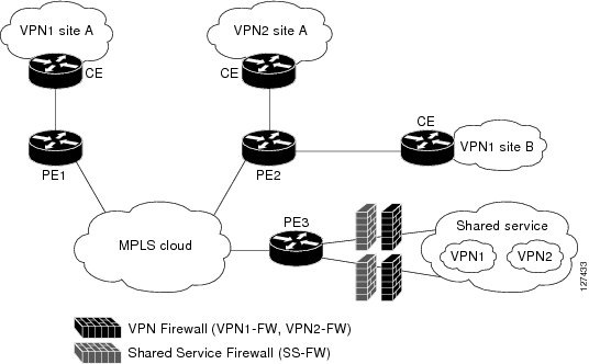
Typically each VPN has a VLAN and/or VRF subinterface connected to the Shared Service. When a packet arrives from an MPLS interface, the inner tag represents the VPN-ID. MPLS routes the packet to the corresponding subinterface that is connected to Shared Service.
A Hub-and-Spoke network requires the following firewall policies:
- VPN Firewall (VPN1-FW and VPN2-FW)--Inspects VPN-generated traffic that is destined to Shared Service and blocks all non-firewall traffic that is coming from Shared Service, thereby protecting the VPN sites from Shared Service traffic. This firewall typically is deployed on the VLAN subinterface of the egress PE router that is connected to the Shared Service network. It is deployed in the outbound direction because the VLAN interface is outbound to the VPN site being protected.
- Shared Service Firewall (SS-FW)--Inspects Shared Service originated traffic that is destined to the VPN/Internet and blocks all non-firewall traffics that is coming from outside, thereby protecting the Shared Service network from VPN/Internet traffic. This firewall typically is deployed on the VLAN interface of the egress PE router that is connected to the Shared Service being protected. It is deployed in the inbound direction because the VLAN interface is inbound to the Shared Service being protected.
- Generic-VPN firewall (GEN-VPN-FW)--Inspects VPN-generated traffic that is destined to the Internet and blocks all non-firewall traffic that is coming from the Internet, thereby protecting all VPNs from the Internet. This firewall typically is deployed on the Internet-facing interface of the PE router that is connected to the Internet. It is deployed in the outbound direction because the Internet-facing interface is outbound to the VPNs being protected.
- Internet firewall (INET-FW)--Inspects Internet-generated traffic that is destined to Shared Service and blocks all non-firewall traffic that is coming from VPNs or Shared Service, thereby protecting the Internet from VPNs. This firewall typically is deployed on the Internet-facing interface of the PE router that is connected to the Internet. It is deployed in the inbound direction because the Internet-facing interface is inbound to the Internet being protected.
How to Configure VRF-Aware Cisco Firewall
- Configuring and Checking ACLs to Ensure that Non-Firewall Traffic is Blocked
- Creating and Naming Firewall Rules and Applying the Rules to an Interface
- Identifying and Setting Firewall Attributes
- Verifying the VRF-Aware Cisco Firewall Configuration and Functioning
Configuring and Checking ACLs to Ensure that Non-Firewall Traffic is Blocked
To configure access control lists (ACLs) and verify that only inspected traffic can pass through the firewall, perform the following steps:
DETAILED STEPS
Creating and Naming Firewall Rules and Applying the Rules to an Interface
DETAILED STEPS
Identifying and Setting Firewall Attributes
DETAILED STEPS
Verifying the VRF-Aware Cisco Firewall Configuration and Functioning
DETAILED STEPS
Configuration Examples for VRF-Aware Cisco Firewall
In the example illustrated in the figure below, a service provider (SP) offers firewall service to VPN customers Bank and Shop. The Bank VPN has the following two sites in a Multiprotocol Label Switching (MPLS) network:
- Site connected to PE1, whose network address is 10.10.1.0/24
- Site connected to PE2, whose network address is 10.10.2.0/24
The Bank VPN also has a VLAN network segment in shared service that is connected to PE3.
The Shop VPN has only one site, which is connected to PE4. The network address 10.10.1.0/24 is the same network address to which the Bank VPN site is connected.
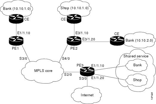
Each VPN needs the following two firewalls:
- VPN firewall to protect the VPN site from shared services.
- Shared service firewall to protect shared service from the VPN site.
In addition, the following two firewalls are required:
- Internet firewall to protect VPNs from the Internet.
- Generic VPN firewall to protect the Internet from VPNs.
In this example, the security policies for Bank and Shop VPNs are as follows:
- Bank VPN firewall--bank_vpn_fw (Inspects FTP, HTTP, and ESMTP protocols)
- Bank shared service firewall--bank_ss_fw (Inspects ESMTP protocol)
- Shop VPN firewall--shop_vpn_fw (Inspects HTTP and RTSP protocols)
- Shop shared service firewall--shop_ss_fw (Inspects H323 protocol)
Security policies for the Internet firewall and generic VPN firewall are as follows:
PE1:
! VRF instance for the Bank VPN
ip vrf bank
rd 100:10
route-target export 100:10
route-target import 100:10

!
! VPN Firewall for Bank VPN protects Bank VPN from Shared Service
ip inspect name bank-vpn-fw ftp
ip inspect name bank-vpn-fw http
ip inspect name bank-vpn-fw esmtp

!
! Shared Service firewall for Bank VPN protects Shared Service from Bank VPN
ip inspect name bank-ss-fw esmtp

!
! VRF interface for the Bank VPN
interface ethernet 0/1.10

!
! description of VPN site Bank to PE1
encapsulation dot1Q 10
ip vrf forwarding bank
ip address 10.10.1.2 255.255.255.0
ip access-group bank-ss-acl in
ip access-group bank-vpn-acl out
ip inspect bank-vpn-fw in
ip inspect bank-ss-fw out

!
! MPLS interface
interface Serial3/0
 ip unnumbered Loopback0

 tag-switching ip

 serial restart-delay 0

!
! ACL that protects the VPN site Bank from Shared Service
ip access-list extended bank-vpn-acl

 permit ip 10.10.2.0 0.0.0.255 10.10.1.0 0.0.0.255

 permit tcp any any eq smtp

 deny   ip  any any log
!
! ACL that protects Shared Service from VPN site Bank
ip access-list extended bank-ss-acl

 permit ip 10.10.1.0 0.0.0.255 10.10.2.0 0.0.0.255

 permit tcp any any eq ftp

 permit tcp any any eq http
 permit tcp any any eq smtp

 deny   ip  any any log
PE2:
! VRF instance for the Bank VPN
ip vrf bank
rd 100:10
route-target export 100:10
route-target import 100:10

!
! VRF instance for the Shop VPN
ip vrf shop
rd 200:20
route-target export 200:20
route-target import 200:20

!
! VPN firewall for Bank BPN protects Bank VPN from Shared Service
ip inspect name bank-vpn-fw ftp
ip inspect name bank-vpn-fw http
ip inspect name bank-vpn-fw esmtp

!
! Shared Service firewall for Bank VPN protects Shared Service from Bank VPN
ip inspect name bank-ss-fw esmtp

!
! VPN firewall for Shop VPN protects Shop VPN from Shared Service
ip inspect name shop-vpn-fw http
ip inspect name shop-vpn-fw rtsp

!
! Shared Service firewall for Shop VPN protects Shared Service from Shop VPN
ip inspect name shop-ss-fw h323
!
! VRF interface for the Bank VPN
interface Ethernet 3/1.10

!
! description of VPN site Bank to PE2
encapsulation dot1Q 10
ip vrf forwarding bank
ip address 10.10.2.2 255.255.255.0
ip access-group bank-ss-acl in
ip access-group bank-vpn-acl out
ip inspect bank-vpn-fw in
ip inspect bank-ss-fw out

!
interface Ethernet 3/1.20

!
! description of VPN site Shop to PE2
encapsulation dot1Q 20
ip vrf forwarding shop
ip address 10.10.1.2 255.255.255.0
ip access-group shop-ss-acl in
ip access-group shop-vpn-acl out
ip inspect shop-vpn-fw in
ip inspect shop-ss-fw out
interface Serial 4/0

 ip unnumbered Loopback0

 tag-switching ip

 serial restart-delay 0

!
! ACL that protects the VPN site Bank from Shared Service
ip access-list extended bank-vpn-acl

 permit ip 10.10.1.0 0.0.0.255 10.10.2.0 0.0.0.255

 permit tcp any any eq smtp

 deny   ip  any any log

!
! ACL that protects Shared Service from VPN site Bank
ip access-list extended bank-ss-acl
 permit ip 10.10.2.0 0.0.0.255 10.10.1.0 0.0.0.255

 permit tcp any any eq ftp

 permit tcp any any eq http

 permit tcp any any eq smtp

 deny   ip  any any log

!
! ACL that protects VPN site Shop from Shared Service
ip access-list extended shop-vpn-acl

 permit tcp any any eq h323

 deny   ip any any log

!
ip access-list extended shop-ss-acl

 permit tcp any any eq http

 permit tcp any any eq rtsp
deny   ip  any any log
PE3:
! VRF instance for the Bank VPN
ip vrf bank
rd 100:10
route-target export 100:10
route-target import 100:10

!
! VRF instance for the Shop VPN
ip vrf shop
rd 200:20
route-target export 200:20
route-target import 200:20

!
! Generic VPN firewall to protect Shop and Bank VPNs from internet
ip inspect name gen-vpn-fw esmtp
ip inspect name gen-vpn-fw ftp
ip inspect name gen-vpn-fw http
ip inspect name gen-vpn-fw rtsp

!
! Internet firewall to prevent malicious traffic from being passed
! to internet from Bank and Shop VPNs
ip inspect name inet-fw esmtp
ip inspect name inet-fw http

!
! VRF interface for the Bank VPN
interface Ethernet 1/1.10

!
! Description of Shared Service to PE3
encapsulation dot1Q 10
ip vrf forwarding bank
ip address 10.10.1.50 255.255.255.0

!
! VRF interface for the Shop VPN
interface Ethernet 1/1.20

!
! Description of Shared Service to PE3
encapsulation dot1Q 20
ip vrf forwarding shop
ip address 10.10.1.50 255.255.255.0
interface Serial 2/0

 ip unnumbered Loopback0

 tag-switching ip

 serial restart-delay 0

!
! VRF interface for the Bank VPN
interface Serial 3/0

!
! Description of Internet-facing interface
ip address 192.168.10.2 255.255.255.0
ip access-group inet-acl out
ip access-group gen-vpn-acl in
ip inspect gen-vpn-fw out
ip inspect inet-fw in

!
! ACL that protects the Bank and Shop VPNs from internet
ip access-list extended gen-vpn-acl

 permit tcp any any eq smtp

 permit tcp any any eq www

 deny   ip  any any log

!
! ACL that protects internet from Bank and Shop VPNs
ip access-list extended inet-acl

 permit tcp any any eq ftp

 permit tcp any any eq http

 permit tcp any any eq smtp

 permit tcp any any eq rtsp

 deny   ip  any any log
PE3:
! VRF instance for the VPN Bank
ip vrf bank
rd 100:10
route-target export 100:10
route-target import 100:10

!
! VRF instance for the VPN Shop
ip vrf shop
rd 200:20
route-target export 200:20
route-target import 200:20

!
! VPN firewall for Bank BPN protects Bank VPN from Shared Service
ip inspect name bank-vpn-fw ftp
ip inspect name bank-vpn-fw http
ip inspect name bank-vpn-fw esmtp

!
! Shared Service firewall for Bank VPN protects Shared Service from Bank VPN
ip inspect name bank-ss-fw esmtp

!
! VPN firewall for Shop VPN protects Shop VPN from Shared Service
ip inspect name shop-vpn-fw http
ip inspect name shop-vpn-fw rtsp

!
! Shared Service firewall for Shop VPN protects Shared Service from Shop VPN
ip inspect name shop-ss-fw h323

!
! Generic VPN firewall protects Shop and Bank VPNs from internet
ip inspect name gen-vpn-fw esmtp
ip inspect name gen-vpn-fw ftp
ip inspect name gen-vpn-fw http
ip inspect name gen-vpn-fw rtsp

!
! Internet firewall prevents malicious traffic from being passed
! to internet from Bank and Shop VPNs
ip inspect name inet-fw esmtp
ip inspect name inet-fw http

!
! VRF interface for the Bank VPN
interface Ethernet 1/1.10

!
! description of Shared Service to PE3
encapsulation dot1Q 10
ip vrf forwarding bank
ip address 10.10.1.50 255.255.255.0
ip access-group bank-ss-acl out
ip access-group bank-vpn-acl in
ip inspect bank-vpn-fw out
ip inspect bank-ss-fw in

!
! VRF interface for the Shop VPN
interface Ethernet 1/1.20
!
! description of Shared Service to PE3
encapsulation dot1Q 20
ip vrf forwarding shop
ip address 10.10.1.50 255.255.255.0
ip access-group shop-ss-acl out
ip access-group shop-vpn-acl in
ip inspect shop-vpn-fw out
ip inspect shop-ss-fw in
interface Serial 2/0

 ip unnumbered Loopback0

 tag-switching ip

 serial restart-delay 0
!
! VRF interface for the Bank VPN
interface Serial 3/0

!
! description of Internet-facing interface
ip address 192.168.10.2 255.255.255.0
ip access-group inet-acl out
ip access-group gen-vpn-acl in
ip inspect gen-vpn-fw out
ip inspect inet-fw in

!
! ACL that protects the VPN site Bank from Shared Service
ip access-list extended bank-vpn-acl

 permit tcp any any eq smtp

 deny   ip  any any log
!
! ACL that protects Shared Service from VPN site Bank
ip access-list extended bank-ss-acl

 permit tcp any any eq ftp

 permit tcp any any eq http

 permit tcp any any eq smtp

 deny   ip  any any log

!
! ACL that protects VPN site Shop from Shared Service
ip access-list extended shop-vpn-acl

 permit tcp any any eq h323

 deny   ip any any log

!
ip access-list extended shop-ss-acl

 permit tcp any any eq http
 permit tcp any any eq rtsp
 deny   ip  any any log
!
! ACL that protects the Bank and Shop VPNs from internet
ip access-list extended gen-vpn-acl

 permit tcp any any eq smtp

 permit tcp any any eq www
 deny   ip  any any log
!
! ACL that protects internet from Bank and Shop VPNs
ip access-list extended inet-acl

 permit tcp any any eq ftp
 permit tcp any any eq http

 permit tcp any any eq smtp

 permit tcp any any eq rtsp

 deny   ip  any any log
In the example illustrated in the figure below, the Cisco firewall is configured on PE1 on the VPN routing and forwarding (VRF) interface E3/1. The host on NET1 wants to reach the server on NET2.
The configuration steps are followed by a sample configuration and log messages.
VRF Configuration on PE1
! configure VRF for host1
ip cef
ip vrf vrf1
rd 100:1
route-target export 100:1
route-target import 100:1
exit
end
!
! apply VRF to the interface facing CE
interface ethernet 3/1
ip vrf forwarding vrf1
ip address 190.1.1.2 255.255.0.0
!
! make the interface facing the MPLS network an MPLS interface
interface serial 2/0
mpls ip
ip address 191.171.151.1 255.255.0.0
!
! configure BGP protocol for MPLS network
router bgp 100
no synchronization
bgp log-neighbor-changes
neighbor 191.171.151.2 remote-as 100
neighbor 191.171.151.2 update-source serial 2/0
no auto-summary
address-family vpnv4
neighbor 191.171.151.2 activate
neighbor 191.171.151.2 send-community both
exit-address-family
address-family ipv4 vrf vrf1
redistribute connected
redistribute static
no auto-summary
no synchronization
exit-address-family
!
! configure VRF static route to reach CE network
ip route vrf vrf1 192.168.4.0 255.255.255.0 190.1.1.1
VRF Configuration on PE2
! configure VRF for host2
ip cef
ip vrf vrf1
rd 100:1
route-target export 100:1
route-target import 100:1
!
! apply VRF on CE-facing interface
interface fastethernet 0/0
ip vrf forwarding vrf1
ip address 193.1.1.2 255.255.255.0
!
! make MPLS network-facing interface an MPLS interface
interface serial 1/0
mpls ip
ip address 191.171.151.2 255.255.0.0
!
! configure BGP protocol for MPLS network
router bgp 100
no synchronization
bgp log-neighbor-changes
neighbor 191.171.151.1 remote-as 100
neighbor 191.171.151.1 update-source serial 1/0
no auto-summary
address-family vpnv4
neighbor 191.171.151.1 activate
neighbor 191.171.151.1 send-community both
exit-address-family
address-family ipv4 vrf vrf1
redistribute connected
redistribute static
no auto-summary
no synchronization
exit-address-family
!configure VRF static route to reach CE network
ip route vrf vrf1 192.168.4.0 255.255.255.0 193.1.1.1
Configuration on CE1
interface e0/1
ip address 190.1.1.1 255.255.255.0
interface e0/0
ip address 192.168.4.2 255.255.255.0
ip route 192.168.104.0 255.255.255.0 190.1.1.2
Configuration on CE2
interface e0/1
ip address 190.1.1.1 255.255.255.0
interface e0/0
ip address 192.168.4.2 255.255.255.0
ip route 192.168.4.0 255.255.255.0 193.1.1.2
Configure Firewall on PE1 and Apply on the VRF Interface
! configure ACL so that NET2 cannot access NET1
ip access-list extended 105
permit tcp any any fragment
permit udp any any fragment
deny tcp any any
deny udp any any
permit ip any any
!
! apply ACL to VRF interface on PE1
interface ethernet 3/1
ip access-group 105 out
!
! configure firewall rule
ip inspect name test tcp
!
! apply firewall rule on VRF interface
interface ethernet 3/1
 ip inspect test in
Check for VRF Firewall Sessions When Host on NET1 Tries to Telnet to Server on NET2
show ip inspect session vrf vrf1
Established Sessions
 Session 659CE534 (192.168.4.1:38772)=>(192.168.104.1:23) tcp SIS_OPEN
!
! checking for ACLs
show ip inspect session detail vrf vrf1 | include ACL 105
  Out SID 192.168.104.1[23:23]=>192.168.4.1[38772:38772] on ACL 105
(34 matches)
Additional References
Related Documents
MIBs
Technical Assistance
|
Description |
Link |
|---|---|
|
The Cisco Support and Documentation website provides online resources to download documentation, software, and tools. Use these resources to install and configure the software and to troubleshoot and resolve technical issues with Cisco products and technologies. Access to most tools on the Cisco Support and Documentation website requires a Cisco.com user ID and password. |
Feature Information for VRF-Aware Cisco Firewall
The following table provides release information about the feature or features described in this module. This table lists only the software release that introduced support for a given feature in a given software release train. Unless noted otherwise, subsequent releases of that software release train also support that feature.
Use Cisco Feature Navigator to find information about platform support and Cisco software image support. To access Cisco Feature Navigator, go to www.cisco.com/go/cfn. An account on Cisco.com is not required.
| Table 1 | Feature Information for VRF-Aware Cisco Firewall |
|
Feature Name |
Releases |
Feature Information |
|---|---|---|
|
VRF-Aware Cisco Firewall |
12.3(14)T |
VRF-aware Cisco firewall applies Cisco firewall functionality to VRF (Virtual Routing and Forwarding) interfaces when the firewall is configured on a service provider (SP) or large enterprise edge device. SPs can provide managed services to small and medium business markets. The VRF-aware Cisco firewall supports VRF-aware URL filtering and VRF-lite (also known as Multi-VRF CE). The following commands were introduced or modified:clearipurlfiltercache, ipinspectalert-off, ipinspectaudittrail, ipinspectdns-timeout, ipinspectmax-incompletehigh, ipinspectmax-incompletelow, ipinspectname, ipinspectone-minutehigh, ipinspectone-minutelow, ipinspecttcpfinwait-time, ipinspecttcpidle-time, ipinspecttcpmax-incompletehost, ipinspecttcpsynwait-time, ipinspectudpidle-time, ipurlfilteralert, ipurlfilterallowmode, ipurlfilteraudit-trail, ipurlfiltercache, ipurlfilterexclusive-domain, ipurlfilterexclusive-domain, ipurlfiltermax-request, ipurlfiltermax-resp-pak, ipurlfilterservervendor, ipurlfilterurlf-server-log, showipinspect, showipurlfiltercache, showipurlfilterconfig, showipurlfilterstatistics. |
Glossary
CE router --customer edge router. A router that is part of a customer network and that interfaces to a provider edge (PE) router.
CBAC --Context-Based Access Control. A protocol that provides internal users with secure access control for each application and for all traffic across network perimeters. CBAC enhances security by scrutinizing both source and destination addresses and by tracking each application's connection status.
data authentication --Refers to one or both of the following: data integrity, which verifies that data has not been altered, or data origin authentication, which verifies that the data was actually sent by the claimed sender.
data confidentiality --A security service where the protected data cannot be observed.
edge router --A router that turns unlabeled packets into labeled packets, and vice versa.
firewall --A router or access server, or several routers or access servers, designated as a buffer between any connected public networks and a private network. A firewall router uses access lists and other methods to ensure the security of the private network.
inspection rule --A rule that specifies what IP traffic (which application-layer protocols) will be inspected by CBAC at an interface.
intrusion detection --The Cisco IOS Firewall's Intrusion Detection System (Cisco IOS IDS) identifies the most common attacks, using signatures to detect patterns of misuse in network traffic.
IPSec --IP Security Protocol. A framework of open standards developed by the Internet Engineering Task Force (IETF). IPSec provides security for transmission of sensitive data over unprotected networks such as the Internet.
managed security services --A comprehensive set of programs that enhance service providers' abilities to meet the growing demands of their enterprise customers. Services based on Cisco solutions include managed firewall, managed VPN (network based and premises based), and managed intrusion detection.
NAT --Network Address Translation. Translates a private IP address used inside the corporation to a public, routable address for use outside of the corporation, such as the Internet. NAT is considered a one-to-one mapping of addresses from private to public.
PE router --provider edge router. A router that is part of a service provider's network and is connected to a customer edge (CE) router.
skinny --Skinny Client Control Protocol (SCCP). A protocol that enables CBAC to inspect Skinny control packets that are exchanged between a Skinny client and the Call Manager (CM); CBAC then configures the router (also known as the Cisco IOS Firewall) to enable the Skinny data channels to traverse through the router.
traffic filtering --A capability that allows you to configure CBAC to permit specified TCP and UDP traffic through a firewall only when the connection is initiated from within the network you want to protect. CBAC can inspect traffic for sessions that originate from either side of the firewall.
traffic inspection --CBAC inspection of traffic that travels through the firewall to discover and manage state information for TCP and UDP sessions. This state information is used to create temporary openings in the firewall's access lists to allow return traffic and additional data connections for permissible sessions (sessions that originated from within the protected internal network).
UDP -- User Datagram Protocol. Connectionless transport layer protocol in the TCP/IP protocol stack. UDP is a simple protocol that exchanges datagrams without acknowledgments or guaranteed delivery, requiring that error processing and retransmission be handled by other protocols.
VPN --Virtual Private Network. Enables IP traffic to travel securely over a public TCP/IP network by encrypting all traffic from one network to another. A VPN uses "tunneling" to encrypt all information at the IP level.
vrf --A VPN routing/forwarding instance. A VRF consists of an IP routing table, a derived forwarding table, a set of interfaces that use the forwarding table, and a set of rules and routing protocols that determine what goes into the forwarding table. In general, a VRF includes the routing information that defines a customer VPN site that is attached to a provider edge (PE) router.
VRF table --A table that stores routing data for each VPN. The VRF table defines the VPN membership of a customer site attached to the network access server (NAS). Each VRF table comprises an IP routing table, a derived Cisco Express Forwarding (CEF) table, and guidelines and routing protocol parameters that control the information that is included in the routing table.
Note | Refer to Internetworking Terms and Acronyms for terms not included in this glossary. |
Cisco and the Cisco logo are trademarks or registered trademarks of Cisco and/or its affiliates in the U.S. and other countries. To view a list of Cisco trademarks, go to this URL: www.cisco.com/go/trademarks. Third-party trademarks mentioned are the property of their respective owners. The use of the word partner does not imply a partnership relationship between Cisco and any other company. (1110R)
Any Internet Protocol (IP) addresses and phone numbers used in this document are not intended to be actual addresses and phone numbers. Any examples, command display output, network topology diagrams, and other figures included in the document are shown for illustrative purposes only. Any use of actual IP addresses or phone numbers in illustrative content is unintentional and coincidental.