
 Feedback
Contents
- Cisco IOS Firewall Stateful Failover
- Finding Feature Information
- Prerequisites for Stateful Failover
- Restrictions for Stateful Failover
- Information About Stateful Failover
- Supported Deployment Scenarios Stateful Failover for the Cisco IOS Firewall
- Stateful Failover Architecture
- State Synchronization
- Bulk Synchronization
- How to Configure Stateful Failover for Cisco IOS Firewalls
- Enabling HSRP IP Redundancy and a Virtual IP Address
- Troubleshooting Tips
- What to Do Next
- Enabling SSO
- Troubleshooting Tips
- What to Do Next
- Enabling Stateful Failover for a Cisco IOS Firewall
- Configuring the Cisco IOS Firewall HA Update Interval
- Troubleshooting Stateful Failover
- Maintaining Firewall Stateful Failover
- Displaying Firewall Stateful Failover Information
- Additional References
- Configuration Examples for Stateful Failover
- Example Stateful Failover
- Feature Information for Cisco IOS Firewall Stateful Failover
Cisco IOS Firewall Stateful Failover
Stateful failover for the Cisco IOS firewall enables a router to continue processing and forwarding firewall session packets after a planned or unplanned outage occurs. You employ a backup (secondary) router that automatically takes over the tasks of the active (primary) router if the active router loses connectivity for any reason. This process is transparent and does not require adjustment or reconfiguration of any remote peer.
Stateful failover for the Cisco IOS firewall is designed to work in conjunction with stateful switchover (SSO) and Hot Standby Routing Protocol (HSRP). HSRP provides network redundancy for IP networks, ensuring that user traffic immediately and transparently recovers from failures in network edge devices or access circuits. That is, HSRP monitors both the inside and outside interfaces so that if either interface goes down, the whole router is deemed to be down and ownership of firewall sessions is passed to the standby router (which transitions to the HSRP active state). SSO allows the active and standby routers to share firewall session state information so that each router has enough information to become the active router at any time. To configure stateful failover for the Cisco IOS firewall, a network administrator should enable HSRP, assign a virtual IP address, and enable the SSO protocol.
- Finding Feature Information
- Prerequisites for Stateful Failover
- Restrictions for Stateful Failover
- Information About Stateful Failover
- How to Configure Stateful Failover for Cisco IOS Firewalls
- Additional References
- Configuration Examples for Stateful Failover
- Feature Information for Cisco IOS Firewall Stateful Failover
Finding Feature Information
Your software release may not support all the features documented in this module. For the latest feature information and caveats, see the release notes for your platform and software release. To find information about the features documented in this module, and to see a list of the releases in which each feature is supported, see the Feature Information Table at the end of this document.
Use Cisco Feature Navigator to find information about platform support and Cisco software image support. To access Cisco Feature Navigator, go to www.cisco.com/go/cfn. An account on Cisco.com is not required.
Prerequisites for Stateful Failover
Complete, Duplicate Cisco IOS Firewall Configuration on the Active and Standby Devices
This document assumes that you have a complete Cisco IOS firewall configuration.
The Cisco IOS firewall configuration that is set up on the active device must be duplicated on the standby device. That is, firewall protocols inspected, the interface ACL's, the global firewall settings and the interface firewall configuration.
Device Requirements
- The active and standby Cisco IOS routers must be running the same Cisco IOS software, Release 12.4(6)T or later.
- Stateful failover for the Cisco IOS firewall requires that your network contains two identical routers that are available to be either the primary or secondary device. Both routers should be the same type of device, have the same CPU and memory.
- This feature is currently supported only on a limited number of platforms. To check the latest platform support, go to Cisco Feature Navigator at http://www.cisco.com/go/fn .
Restrictions for Stateful Failover
When configuring redundancy for a Cisco IOS firewall, the following restrictions exist:
- Both the active and standby devices must run the identical version of the Cisco IOS software, and both the active and standby devices must be connected via hub or switch.
- HSRP requires the inside interface to be connected via LANs.
- Load balancing is not supported; that is, no more than one device in a redundancy group can be active at any given time.
- Any restrictions that exist for intradevice SSO will also exist for the firewall High Availability (HA). The behavior of intra-device active where the Active device re-boots when the SSO state changes from Active to anything will be the same with firewall HA.
- No support for configuration synchronization and In-Service Software Upgrade (ISSU) which are not yet available for intra-box failover in Cisco IOS T releases.
- Stateful failover of the Cisco IOS firewall is not supported with Zone-Based Policy firewall configuration.
- This phase of the feature will not provide support for asymmetric routing and it is the responsibility of the user to configure the network to avoid this.
- The stateful failover feature does not synchronize any statistics or mib firewall information between the active and standby devices.
- The stateful failover feature does not support rate-limiting of firewall sessions on the standby router for the failed over sessions.
- Currently only Layer 4 TCP and UDP protocol failover is supported. Therefore, all TCP only sessions, UDP only sessions, and single channel granular protocols sessions for which L7 inspection is not supported are failed over.
- Layer 4 ICMP session will not be failed over to the standby
- Any session configured for Layer 7 inspection will NOT be failed over.
- CiscoIntrusion Prevention Services (IPS)/Intrusion Detection Services (IDS) feature will not be made HA aware in this release.
Information About Stateful Failover
- Supported Deployment Scenarios Stateful Failover for the Cisco IOS Firewall
- Stateful Failover Architecture
Supported Deployment Scenarios Stateful Failover for the Cisco IOS Firewall
It is recommended that you implement stateful failover in one of the following recommended deployment scenarios:
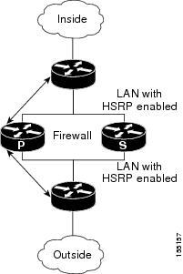
In a dual LAN interface scenario, the active and standby routers running the firewall are connected to each other via LAN interface on both the inside and the outside (see the figure below). HSRP is configured on both the inside and outside interface. The next hop routers in this scenario talk to the HA pair via the virtual IP address. In this scenario there are two virtual IP address, one on the inside and the other on the outside. Virtual IP addresses cannot be advertised using routing protocols. You need to create static routes on the next hops to get to the virtual IP address.
You need to configue HSRP tracking in order to track multiple pairs of interfaces. If you run HSRP on only one pair of interfaces, or run on both without mutual tracking of the pairs, each pair functions independently of each other and are unaware of each other's state changes. For example, if HSRP is run on only the two outside interfaces (as shown in the figure below), this could cause HSRP to failover on the outside interfaces, whilst the inside interfaces are unchanged. This causes the black holing of traffic, which continues to be directed to the primary from the inside. This introduces the possibility of problems arising from one interface on a primary router failing and triggering a move to the secondary, while the other interface on the ex-primary remains active. Mutual tracking means that if the outside interface does fail, the inside interface on the same router will also be deemed down allowing for complete router failover to the secondary.
In a LAN WAN scenario, the inside interface of the Active Standby pair running the firewall are connected via LAN interface on the inside and WAN interface on the outside (see the figure below). HSRP is configured on the inside interface. The inside network communicates with the HA pair using the inside virtual IP address.
HSRP tracking should be configured on the inside LAN interfaces to track the state of the outside WAN interface. If the outside WAN interface goes down on the active the LAN interface that is tracking it reduces the HSRP priority and initiates a failover to the standby. Traffic from the outside flowing into the HSRP pair should now be directed to the new active device.
In the scenario where the LAN interfaces track the WAN interfaces, the failover to the standby happens immediately. However, for traffic to start flowing on the new active router, routing convergence needs to happen. The net failover time is dictated by the routing protocol.
In this scenario the traffic flows from the inside to the outside through the Active due to the HSRP configuration on the inside LAN interfaces. The traffic from the outside to the inside should also flow through the active device. The configuration of the network so that the traffic always flows through the active is beyond the scope of this document. In this scenario, the network administrator is responsible to ensure that the traffic always flows through the active device.
Stateful Failover Architecture
Firewall stateful failover is a client of Cisco IOS SSO. SSO is a method of providing redundancy and synchronization for Cisco IOS applications and features.
State Synchronization
The synchronization manager will be responsible for checking firewall to determine the state of the active device, which must be check pointed to the redundant peers and update that state on the firewall on standby devices.
Periodic updates are sent from the active to the standby for all HA sessions. This information enables the standby to take over the sessions and process the sessions if there is a failover.
The stateful failover feature supports deterministic updates. This means that the updates for a session get sent every N seconds, where N is configurable. Default value for N is 10 sec.
Bulk Synchronization
Bulk synchronization happens at boot time or when you use the clear ip inspect ha sessions allcommand on the standby device. If the standby device is configured after the active device already has sessions, then only new ha sessions established on the active device are synchronized to the standby device through dynamic synchronization. If you want all the current sessions synchronized from the active to the standby, you must specifically issue the clear ip inspect ha sessions allcommand on the standby device. A single request message is sent from the standby device to the active device which result in add_session messages from active to standby for all sessions open on the active at that time.
How to Configure Stateful Failover for Cisco IOS Firewalls
- Enabling HSRP IP Redundancy and a Virtual IP Address
- Enabling SSO
- Enabling Stateful Failover for a Cisco IOS Firewall
- Configuring the Cisco IOS Firewall HA Update Interval
- Troubleshooting Stateful Failover
- Maintaining Firewall Stateful Failover
- Displaying Firewall Stateful Failover Information
Enabling HSRP IP Redundancy and a Virtual IP Address
HSRP provides two services--IP redundancy and a Virtual IP (VIP) address. Each HSRP group may provide either or both of these services. Cisco IOS firewall stateful failover uses the IP redundancy services from only one HSRP standby group. It can use the VIP address from one or more HSRP groups. Use the following task to configure HSRP on the outside and inside interfaces of the router.
 Note | Perform this task on both routers (active and standby) and on both interfaces of each router. |
If a switch connects the active and standby routers, you must perform one of the following steps to ensure that the correct settings are configured on that switch:
- Enable the spanning-tree portfast command on every switch port that connects to a HSRP-enabled router interface.
- Disable the Spanning Tree Protocol (STP) on the switch only if your switch does not connect to other switches. Disabling spanning tree in a multi-switch environment may cause network instability.
- Enable the standby delay minimum [min-delay] reload [reload-delay] command if you do not have access to the switch. The reload-delay argument should be set to a value of at least 120 seconds. This command must be applied to all HSRP interfaces on both routers.
For more information on HSRP instability, see the document Avoiding HSRP Instability in a Switching Environment with Various Router Platforms .
Note | You must perform at least one of these steps for correct HSRP operation. |
DETAILED STEPS
Enabling SSO
Use this task to enable SSO, which is used to transfer Cisco IOS firewall session state information between two routers.
SSO is a method of providing redundancy and synchronization for many Cisco IOS applications and features. SSO is necessary for the Cisco IOS firewall to learn about the redundancy state of the network and to synchronize their internal application state with their redundant peers.
- You should configure HSRP before enabling SSO.
- To avoid losing SCTP communication between peers, be sure to include the following commands to the local address section of the SCTP section of the IPC configuration:
DETAILED STEPS
| Command or Action | Purpose | |||
|---|---|---|---|---|
Step 1 |
enable
Example: Router> enable |
Enables privileged EXEC mode. | ||
Step 2 |
configure
terminal
Example: Router# configure terminal |
Enters global configuration mode. | ||
Step 3 |
redundancy
inter-device
Example: Router(config)# redundancy inter-device |
Configures redundancy and enters inter-device configuration mode. To exit inter-device configuration mode, use the exit command. To remove all inter-device configuration, use the no form of the command. | ||
Step 4 |
scheme
standby
standby-group-name
Example: Router(config-red-interdevice)# scheme standby HA-in |
Defines the redundancy scheme that is to be used. Currently, "standby" is the only supported scheme.
| ||
Step 5 |
exit
Example: Router(config-red-interdevice)# exit |
Exits inter-device configuration mode. | ||
Step 6 |
ipc
zone
default
Example: Router(config)# ipc zone default |
Configures the inter-device communication protocol, Inter-Process Communication (IPC), and enters IPC zone configuration mode. Use this command to initiate the communication link between the active router and standby router. | ||
Step 7 |
association
1
Example: Router(config-ipczone)# association 1 |
Configures an association between the two devices and enters IPC association configuration mode. | ||
Step 8 |
protocol
sctp
Example: Router(config-ipczone-assoc)# protocol sctp |
Configures Stream Control Transmission Protocol (SCTP) as the transport protocol and enters SCTP protocol configuration mode. | ||
Step 9 |
local-port
local-port-number
Example: Router(config-ipc-protocol-sctp)# local-port 5000 |
Defines the local SCTP port number that is used to communicate with the redundant peer and puts you in IPC transport - SCTP local configuration mode. | ||
Step 10 |
local-ip
device-real-ip-address
[device-real-ip-address2
Example: Router(config-ipc-local-sctp)# local-ip 10.0.0.1 |
Defines at least one local IP address that is used to communicate with the redundant peer. The local IP addresses must match the remote IP addresses on the peer router. There can be either one or two IP addresses, which must be in the global VRF. A virtual IP address cannot be used. | ||
Step 11 |
retransmit-timeout
retran-min
[msec]
retran-max [msec]
Example: Router(config-ipc-local-sctp)# retransmit-timeout 300 10000 |
Configures the maximum amount of time, in milliseconds, that SCTP will wait before retransmitting data. | ||
Step 12 |
path-retransmit
max-path-retries
Example: Router(config-ipc-local-sctp)# path-retransmit 10 |
Configures the number of consecutive retransmissions SCTP will perform before failing a path within an association. | ||
Step 13 |
assoc-
retransmit retries
Example: Router(config-ipc-local-sctp)# assoc -retransmit 10 |
Configures the number of consecutive retransmissions SCTP will perform before failing an association. | ||
Step 14 |
exit
Example: Router(config-ipc-local-sctp)# exit |
Exits IPC transport - SCTP local configuration mode. | ||
Step 15 |
remote-port
remote-port-number
Example: Router(config-ipc-protocol-sctp)# remote-port 5000 |
Defines the remote SCTP port number that is used to communicate with the redundant peer and puts you in IPC transport - SCTP remote configuration mode.
| ||
Step 16 |
remote-ip
peer-real-ip-address
[peer-real-ip-address2
Example: Router(config-ipc-remote-sctp)# remote-ip 10.0.0.2 |
Defines at least one remote IP address of the redundant peer that is used to communicate with the local device. All remote IP addresses must refer to the same device. A virtual IP address cannot be used. |
Examples
The following example shows how to enable SSO:
!
redundancy inter-device
 scheme standby HA-in
!
!
ipc zone default
 association 1
  no shutdown
  protocol sctp
   local-port 5000
    local-ip 10.0.0.1
    retransmit-timeout 300 10000
    path-retransmit 10
    assoc-retransmit 10
   remote-port 5000
    remote-ip 10.0.0.2
!
Enabling Stateful Failover for a Cisco IOS Firewall
Before performing this task, the Cisco IOS firewall inspect rule must be configured. Also, HSRP and SSO must be configured to enable box-to-box redundancy.
Note | The inspect rules should not have ICMP or protocols for which Cisco IOS firewall supports Layer 7 inspection. > |
DETAILED STEPS
| Command or Action | Purpose | |||
|---|---|---|---|---|
Step 1 |
enable
Example: Router> enable |
Enables privileged EXEC mode.
| ||
Step 2 |
configure
terminal
Example: Router# configure terminal |
Enters global configuration mode. | ||
Step 3 |
interface
[interface-name] Example: Router (config)# interface interface1 |
Defines the interface. | ||
Step 4 |
ip
inspect
[rule] in| out redundancy stateful [hsrp-group-name] Example: Router (config)# ip inspect rule1 in/out redundancy stateful group101 Example:
|
Enables stateful failover for this inspect rule.
| ||
Step 5 |
exit
Example: Router (config)# exit |
Exit global configuration mode |
Configuring the Cisco IOS Firewall HA Update Interval
Use this task to change the amount of time between each update to the standby. The default interval of 10 seconds.
DETAILED STEPS
| Command or Action | Purpose | |
|---|---|---|
Step 1 |
enable
Example: Router> enable |
Enables privileged EXEC mode.
|
Step 2 |
configure
terminal
Example: Router# configure terminal |
Enters global configuration mode. |
Step 3 |
ip inspect redundancy update seconds [10-60] Example: Router (config)# ip inspect redundancy upate seconds 20 Example:
|
Changes the amount of time between each update to the standby. The default interval of 10 seconds is used if you do not specify a value. |
Step 4 |
exit
Example: Router (config)# exit |
Exit global configuration mode |
Troubleshooting Stateful Failover
The following commands may be used to display information about Stateful Failover messages or sessions. The debug commands may be used in any order or independent of the other debug commands.
DETAILED STEPS
| Command or Action | Purpose | |
|---|---|---|
Step 1 |
enable
Example: Router# enable |
Enables privileged EXEC mode.
|
Step 2 |
debug
ip
inspect
ha
[manager | update] Example: Router# debug ip inspect ha manager |
Displays enough information to identify problems with add/delete to ha sessions.
|
Maintaining Firewall Stateful Failover
The clear ip inspect ha commandis usedto clear all inspect ha sessions on the device. If the device is the standby device then it initiates a bulk sync of all session from the active. It is also used to clear the ha statistics on the device
DETAILED STEPS
| Command or Action | Purpose | |
|---|---|---|
Step 1 |
enable
Example: Router> enable |
Enables privileged EXEC mode.
|
Step 2 |
clear
ip
inspect
ha
[sessions-all | statistics] Example: Router# clear ip inspect ha sessions-all all |
The options for this command are:
|
Displaying Firewall Stateful Failover Information
Use the show ip inspect ha{sessions [detail] | statistics} [vrf vrf-name]}command to display firewall stateful failover information.
DETAILED STEPS
| Command or Action | Purpose | |
|---|---|---|
Step 1 |
enable
Example: Router> enable |
Enables privileged EXEC mode. |
Step 2 |
show
ip
inspect
ha
{session [detail] |
statistics} [vrf
vrf-name]}
Example: Router# show ip inspect ha session |
The options for this command are:
|
The following tables provide examples of Stateful Failover error messages and alert message.
The table below contains the stateful failover HA error messages.
| Table 1 | Stateful Failover Error Messages |
|
Message |
Meaning |
|---|---|
*Apr 13 17:09:20.539: %FW_HA-3-SUBSYS_INIT_FAILED: Firewall High availability subsystem initialization failed |
The HA subsystem initialization failed. |
*Apr 13 16:50:30.007: %FW_HA-3-TW_INIT_FAILED: Firewall High availability update timer initialization failed |
The HA timer wheel initialization failed. |
*Apr 13 16:50:30.007: %FW_HA-3-RF_REG_FAILED: Firewall High availability registration to RF failed *Apr 13 16:50:30.007: %FW_HA-3-CF_REG_FAILED: Firewall High availability registration to CF failed |
Registration to SSO RF/CF failed. |
May 20 21:57:10.475: %FW_HA-6-NO_INSPECT_RULE_ON_STDBY: Firewall High availability - inspect rule is not configured on standby for interface e0/0 dir in/out |
The Inspect rule is not configured on the standby device. |
*May 20 21:57:10.475: %FW_HA-6-PROT_MISMATCH: Firewall High availability - L4/L7 protocol mismatch between active and standby |
Protocol mismatch between the active and standby devices. |
May 20 21:57:10.475: %FW_HA-6-NO_HSRP_GNAME_ON_STDBY: Firewall High availability - Inpsect redundancy group is not configured on standby for interface e0/0 dir in/out |
The HSRP group is not configured on the standby device. |
*May 20 21:57:10.475: %FW_HA-6-CONFIG_MISMATCH: Firewall High availability - Inspect HA config mismatch between active and standby. act:inspect rule a_test, hsrp_grp a_hsrp_group; stdby:inspect rule s_test hsrp_grp s_hsrp_group |
HA configuration mismatch between the active and standby devices. |
If audit trail is configured on the standby HA device the standard alerts that are shown when a session is added or deleted will be changed to reflect that the session is a standby session. The table below contains the stateful failover alert messages.
| Table 2 | Stateful Failover Alert Messages |
|
Message |
Meaning |
|---|---|
*Apr 14 23:53:44.641: %FW-HA-6-SESS_AUDIT_TRAIL_STDBY_START: Start tcp standby session: initiator (10.0.0.10:22955) -- responder (11.0.0.10:23) |
The Standby session is up. |
*Apr 14 23:57:52.891: %FW-HA-6-SESS_AUDIT_TRAIL_STDBY_STOP: Stop tcp standby session: initiator (10.0.0.10:35148) -- responder (11.0.0.10:23) |
The Standby session is down. |
*Apr 14 23:57:52.891: %FW-HA-6-SESS_AUDIT_TRAIL_STDBY_TO_ACT: Firewall HA transitioning from Standby to Active HA state |
The device has transitioned from standby to active. |
Additional References
MIBs
Technical Assistance
| Description | Link |
|---|---|
|
The Cisco Support and Documentation website provides online resources to download documentation, software, and tools. Use these resources to install and configure the software and to troubleshoot and resolve technical issues with Cisco products and technologies. Access to most tools on the Cisco Support and Documentation website requires a Cisco.com user ID and password. |
Configuration Examples for Stateful Failover
Example Stateful Failover
The following output example shows stateful failover that has been configured on a Cisco IOS router:
Router 1)
hostname ha-R1
!
boot-start-marker
boot-end-marker
!
!
redundancy inter-device
scheme standby HAin
!
!
redundancy
logging buffered 10000000 debugging
logging rate-limit console 10000
!
no aaa new-model
!
resource policy
!
!
ipc zone default
association 1
no shutdown
protocol sctp
local-port 5000
local-ip 10.0.0.1
remote-port 5000
remote-ip 10.0.0.2
!
!
ip inspect tcp idle-time 180
ip inspect name ha-protocols tcp
ip inspect name ha-protocols udp
ip inspect redundancy update seconds 60
!
!
!inside interface
interface Ethernet0/0
ip address 10.0.0.1 255.255.255.0
standby delay minimum 120 reload 120
standby 1 ip 10.0.0.3
standby 1 timers 1 10
standby 1 priority 60
standby 1 preempt
standby 1 name HAin
standby 1 track Ethernet1/0
!
!outside interface
interface Ethernet1/0
ip address 211.0.0.1 255.255.255.0
ip access-group fw-ha-acl in
!! The HSRP group used with the inspect config should be the inside HSRP group
ip inspect ha-protocols out redundancy stateful HAin
standby delay minimum 120 reload 120
standby 2 ip 211.0.0.3
standby 2 timers 1 10
standby 2 priority 60
standby 2 preempt
standby 2 name HAout
standby 2 track Ethernet0/0
!
!
!
! ACL on interface should permit HSRP, HA traffic from active to standby device
ip access-list extended fw-ha-acl
permit ip host 211.0.0.2 host 211.0.0.1
permit ip host 211.0.0.1 host 211.0.0.2
deny any any
!
!
!
!
line con 0
exec-timeout 0 0
line aux 0
##########################################################################
Router 2)
hostname ha-R2
!
boot-start-marker
boot-end-marker
!
!
redundancy inter-device
scheme standby HAin
!
!
redundancy
logging buffered 10000000 debugging
logging rate-limit console 10000
!
no aaa new-model
!
resource policy
!
!
ipc zone default
association 1
no shutdown
protocol sctp
local-port 5000
local-ip 10.0.0.2
remote-port 5000
remote-ip 10.0.0.1
!
!
ip inspect tcp idle-time 180
ip inspect name ha-protocols tcp
ip inspect name ha-protocols udp
ip inspect redundancy update seconds 60
!
!
!inside interface
interface Ethernet0/0
ip address 10.0.0.2 255.255.255.0
standby delay minimum 120 reload 120
standby 1 ip 10.0.0.3
standby 1 priority 60
standby 1 preempt
standby 1 name HAin
standby 1 track Ethernet1/0
!
!outside interface
interface Ethernet1/0
ip address 211.0.0.2 255.255.255.0
ip access-group fw-ha-acl in
!! The HSRP group used with the inspect config should be the inside HSRP group
ip inspect ha-protocols out redundancy stateful HAin
standby delay minimum 120 reload 120
standby 2 ip 211.0.0.3
standby 2 priority 60
standby 2 preempt
standby 2 name HAout
standby 2 track Ethernet0/0
!
!
!
! ACL on interface should permit HSRP, HA traffic from active to standby device
ip access-list extended fw-ha-acl
permit ip host 211.0.0.2 host 211.0.0.1
permit ip host 211.0.0.1 host 211.0.0.2
!
!
!
!
line con 0
exec-timeout 0 0
line aux 0
Feature Information for Cisco IOS Firewall Stateful Failover
The following table provides release information about the feature or features described in this module. This table lists only the software release that introduced support for a given feature in a given software release train. Unless noted otherwise, subsequent releases of that software release train also support that feature.
Use Cisco Feature Navigator to find information about platform support and Cisco software image support. To access Cisco Feature Navigator, go to www.cisco.com/go/cfn. An account on Cisco.com is not required.
| Table 3 | Feature Information for Cisco IOS Firewall Stateful Failover |
|
Cisco IOS Firewall Stateful Failover |
12.4(6)T |
With the introduction of the Stateful Failover, applications and network services are not disrupted if an interface on a router is lost or if a router crashes. With a Stateful Failover configuration, the standby or backup router maintains state information so that firewall operations are maintained in the event of a failure. The following commands are introduced or modified in the feature: clear ip inspect ha, debug ip inspect ha, ip inspect, show ip inspect, show ip inspect ha. |
Cisco and the Cisco logo are trademarks or registered trademarks of Cisco and/or its affiliates in the U.S. and other countries. To view a list of Cisco trademarks, go to this URL: www.cisco.com/go/trademarks. Third-party trademarks mentioned are the property of their respective owners. The use of the word partner does not imply a partnership relationship between Cisco and any other company. (1110R)
Any Internet Protocol (IP) addresses and phone numbers used in this document are not intended to be actual addresses and phone numbers. Any examples, command display output, network topology diagrams, and other figures included in the document are shown for illustrative purposes only. Any use of actual IP addresses or phone numbers in illustrative content is unintentional and coincidental.