
 Feedback
Contents
- IPsec Virtual Tunnel Interface
- Finding Feature Information
- Restrictions for IPsec Virtual Tunnel Interface
- Information About IPsec Virtual Tunnel Interface
- Benefits of Using IPsec Virtual Tunnel Interfaces
- Static Virtual Tunnel Interfaces
- Dynamic Virtual Tunnel Interfaces
- Traffic Encryption with the IPsec Virtual Tunnel Interface
- Multi-SA Support for Dynamic Virtual Tunnel Interfaces for IKEv1
- Multi-SA Support for Dynamic Virtual Tunnel Interfaces for IKEv2
- Dynamic Virtual Tunnel Interface Life Cycle
- Routing with IPsec Virtual Tunnel Interfaces
- How to Configure IPsec Virtual Tunnel Interface
- Configuring Static IPsec Virtual Tunnel Interfaces
- Configuring Dynamic IPsec Virtual Tunnel Interfaces
- Configuring Multi-SA Support for Dynamic Virtual Tunnel Interfaces Using IKEv1
- Configuring Multi-SA Support for Dynamic Virtual Tunnel Interfaces Using IKEv2
- Defining an AAA Attribute List
- Configuring the VRF
- Configuring Internet Key Exchange Version 2 (IKEv2)
- Configuring the IKEv2 Proposal
- Configuring the IKEv2 Policy
- Configuring the IKEv2 Keyring
- Configuring the IKEv2 Profile
- Configuring an IPsec Profile and a Virtual Template
- Configuration Examples for IPsec Virtual Tunnel Interface
- Example: Static Virtual Tunnel Interface with IPsec
- Example: Verifying the Results for the IPsec Static Virtual Tunnel Interface
- Example: VRF-Aware Static Virtual Tunnel Interface
- Example: Static Virtual Tunnel Interface with QoS
- Example: Static Virtual Tunnel Interface with Virtual Firewall
- Example: Dynamic Virtual Tunnel Interface Easy VPN Server
- Verifying the Results for the Dynamic Virtual Tunnel Interface Easy VPN Server Example
- Example: Dynamic Virtual Tunnel Interface Easy VPN Client
- Verifying the Results for the Dynamic Virtual Tunnel Interface Easy VPN Client Example
- Example: VRF-Aware IPsec with a Dynamic VTI When VRF is Configured Under a Virtual Template
- Example: VRF-Aware IPsec with Dynamic VTI When VRF is Configured Under a Virtual Template with the Gateway Option in an IPsec Profile
- Example: VRF-Aware IPsec with a Dynamic VTI When VRF is Configured Under an ISAKMP Profile
- Example: VRF-Aware IPsec with a Dynamic VTI When VRF is Configured Under an ISAKMP Profile and a Gateway Option in an IPsec Profile
- Example: VRF-Aware IPsec with a Dynamic VTI When a VRF is Configured Under Both a Virtual Template and an ISAKMP Profile
- Example: Configuring Multi-SA Support for Dynamic VTI Using IKEv2
- Example: Dynamic Virtual Tunnel Interface with Virtual Firewall
- Example: Dynamic Virtual Tunnel Interface with QoS
- Example: Dynamic Virtual Tunnel Interface Using GRE with IPsec Protection
- Additional References
- Feature Information for IPsec Virtual Tunnel Interface
IPsec Virtual Tunnel Interface
IP security (IPsec) virtual tunnel interfaces (VTIs) provide a routable interface type for terminating IPsec tunnels and an easy way to define protection between sites to form an overlay network. IPsec VTIs simplify configuration of IPsec for protection of remote links, support multicast, and simplify network management and load balancing.
- Finding Feature Information
- Restrictions for IPsec Virtual Tunnel Interface
- Information About IPsec Virtual Tunnel Interface
- How to Configure IPsec Virtual Tunnel Interface
- Configuration Examples for IPsec Virtual Tunnel Interface
- Additional References
- Feature Information for IPsec Virtual Tunnel Interface
Finding Feature Information
Your software release may not support all the features documented in this module. For the latest feature information and caveats, see the release notes for your platform and software release. To find information about the features documented in this module, and to see a list of the releases in which each feature is supported, see the Feature Information Table at the end of this document.
Use Cisco Feature Navigator to find information about platform support and Cisco software image support. To access Cisco Feature Navigator, go to www.cisco.com/go/cfn. An account on Cisco.com is not required.
Restrictions for IPsec Virtual Tunnel Interface
IKE Security Association
The Internet Key Exchange (IKE) security association (SA) is bound to the VTI. Therefore the same IKE SA cannot be used for a crypto map.
IPsec SA Traffic Selectors
Static VTIs (SVTIs) support only a single IPsec SA that is attached to the VTI interface. The traffic selector for the IPsec SA is always "IP any any."
A dynamic VTI (DVTIs) also is a point-point interface that can support multiple IPsec SAs. The DVTI can accept the multiple IPsec selectors that are proposed by the initiator.
IPv4 and IPv6 Packets
This feature supports SVTIs that are configured to encapsulate IPv4 packets or IPv6 packets, but IPv4 packets cannot carry IPv6 packets, and IPv6 packets cannot carry IPv4 packets.
Proxy
SVTIs support only the "IP any any" proxy.
DVTIs support multiple proxies, but DVTIs do not allow mixing "any any" proxies with non-"any any" proxies. DVTIs permit only one type at a time, either a single "any any" proxy or multiple "no any any" proxies.
Tunnel Protection
Do not configure the shared keyword when using the tunnel mode ipsec ipv4 command for IPsec IPv4 mode.
Static VTIs Versus GRE Tunnels
The IPsec VTI is limited to IP unicast and multicast traffic only, as opposed to Generic Routing Encapsulation (GRE) tunnels, which have a wider application for IPsec implementation.
VRF-Aware IPsec Configuration
VPN routing and forwarding (VRF) mustnot be configured in the Internet Security Association and Key Management Protocol (ISAKMP) profile in VRF-aware IPsec configurations with either SVTIs or DVTIs. Instead, the VRF must be configured on the tunnel interface for SVTIs. For DVTIs, you must apply the VRF to the virtual template using the ip vrf forwarding command.
Single Template Model
In the single template model, the VRF is configured in the ISAKMP profile. In this model, each virtual access that is created belongs to the internal VRF (IVRF) specified in the ISAKMP profile. But because the IP address of the virtual access is derived from the interface to which the virtual access is unnumbered to, the IP address of the interface will not be available in the virtual access routing table. This happens because the unnumbered interface does not belong to the IVRF routing table of the virtual access. In such cases, a ping to virtual access IP address fails.
Information About IPsec Virtual Tunnel Interface
The use of IPsec VTIs both greatly simplifies the configuration process when you need to provide protection for remote access and provides a simpler alternative to using generic routing encapsulation (GRE) or Layer 2 Tunneling Protocol (L2TP) tunnels for encapsulation and crypto maps with IPsec. A major benefit associated with IPsec VTIs is that the configuration does not require a static mapping of IPsec sessions to a physical interface. The IPsec tunnel endpoint is associated with an actual (virtual) interface. Because there is a routable interface at the tunnel endpoint, many common interface capabilities can be applied to the IPsec tunnel.
The IPsec VTI allows for the flexibility of sending and receiving both IP unicast and multicast encrypted traffic on any physical interface, such as in the case of multiple paths. Traffic is encrypted or decrypted when it is forwarded from or to the tunnel interface and is managed by the IP routing table. Using IP routing to forward the traffic to the tunnel interface simplifies the IPsec VPN configuration compared to the more complex process of using access control lists (ACLs) with the crypto map in native IPsec configurations. Because DVTIs function like any other real interface you can apply quality of service (QoS), firewall, and other security services as soon as the tunnel is active.
Without VPN Acceleration Module2+ (VAM2+) accelerating virtual interfaces, the packet traversing an IPsec virtual interface is directed to the Router Processor (RP) for encapsulation. This method tends to be slow and has limited scalability. In hardware crypto mode, all the IPsec VTIs are accelerated by the VAM2+ crypto engine, and all traffic going through the tunnel is encrypted and decrypted by the VAM2+.
The following sections provide details about the IPsec VTI:
- Benefits of Using IPsec Virtual Tunnel Interfaces
- Static Virtual Tunnel Interfaces
- Dynamic Virtual Tunnel Interfaces
- Traffic Encryption with the IPsec Virtual Tunnel Interface
- Multi-SA Support for Dynamic Virtual Tunnel Interfaces for IKEv1
- Multi-SA Support for Dynamic Virtual Tunnel Interfaces for IKEv2
- Dynamic Virtual Tunnel Interface Life Cycle
- Routing with IPsec Virtual Tunnel Interfaces
Benefits of Using IPsec Virtual Tunnel Interfaces
IPsec VTIs allow you to configure a virtual interface to which you can apply features. Features for clear-text packets are configured on the VTI. Features for encrypted packets are applied on the physical outside interface. When IPsec VTIs are used, you can separate the application of features such as NAT, ACLs, and QoS and apply them to clear-text or encrypted text, or both. When crypto maps are used, there is no simple way to apply encryption features to the IPsec tunnel.
There are two types of VTI interfaces: static VTIs (SVTIs) and dynamic VTIs (DVTIs).
Static Virtual Tunnel Interfaces
SVTI configurations can be used for site-to-site connectivity in which a tunnel provides always-on access between two sites. The advantage of using SVTIs as opposed to crypto map configurations is that users can enable dynamic routing protocols on the tunnel interface without the extra 24 bytes required for GRE headers, thus reducing the bandwidth for sending encrypted data.
Additionally, multiple Cisco IOS software features can be configured directly on the tunnel interface and on the physical egress interface of the tunnel interface. This direct configuration allows users to have solid control on the application of the features in the pre- or post-encryption path.
The figure below illustrates how a SVTI is used.
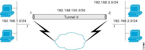
The IPsec VTI supports native IPsec tunneling and exhibits most of the properties of a physical interface.
Dynamic Virtual Tunnel Interfaces
DVTIs can provide highly secure and scalable connectivity for remote-access VPNs. The DVTI technology replaces dynamic crypto maps and the dynamic hub-and-spoke method for establishing tunnels.
DVTIs can be used for both the server and remote configuration. The tunnels provide an on-demand separate virtual access interface for each VPN session. The configuration of the virtual access interfaces is cloned from a virtual template configuration, which includes the IPsec configuration and any Cisco IOS software feature configured on the virtual template interface, such as QoS, NetFlow, or ACLs.
DVTIs function like any other real interface so that you can apply QoS, firewall, other security services as soon as the tunnel is active. QoS features can be used to improve the performance of various applications across the network. Any combination of QoS features offered in Cisco IOS software can be used to support voice, video, or data applications.
DVTIs provide efficiency in the use of IP addresses and provide secure connectivity. DVTIs allow dynamically downloadable per-group and per-user policies to be configured on a RADIUS server. The per-group or per-user definition can be created using extended authentication (Xauth) User or Unity group, or it can be derived from a certificate. DVTIs are standards based, so interoperability in a multiple-vendor environment is supported. IPsec DVTIs allow you to create highly secure connectivity for remote access VPNs and can be combined with Cisco Architecture for Voice, Video, and Integrated Data (AVVID) to deliver converged voice, video, and data over IP networks. The DVTI simplifies Virtual Private Network (VRF) routing and forwarding- (VRF-) aware IPsec deployment. The VRF is configured on the interface.
A DVTI requires minimal configuration on the router. A single virtual template can be configured and cloned.
The DVTI creates an interface for IPsec sessions and uses the virtual template infrastructure for dynamic instantiation and management of dynamic IPsec VTIs. The virtual template infrastructure is extended to create dynamic virtual-access tunnel interfaces. DVTIs are used in hub-and-spoke configurations. A single DVTI can support several static VTIs.
 Note | DVTI is supported only in Easy VPNs. That is, the DVTI end must be configured as an Easy VPN server. |
figure below illustrates the DVTI authentication path.
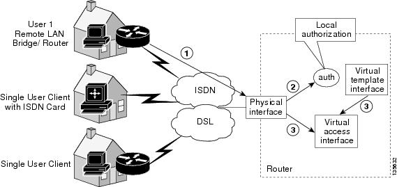
The authentication shown in the figure above follows this path:
Traffic Encryption with the IPsec Virtual Tunnel Interface
When an IPsec VTI is configured, encryption occurs in the tunnel. Traffic is encrypted when it is forwarded to the tunnel interface. Traffic forwarding is handled by the IP routing table, and dynamic or static routing can be used to route traffic to the SVTI. DVTI uses reverse route injection to further simplify the routing configurations. Using IP routing to forward the traffic to encryption simplifies the IPsec VPN configuration because the use of ACLs with a crypto map in native IPsec configurations is not required. The IPsec virtual tunnel also allows you to encrypt multicast traffic with IPsec.
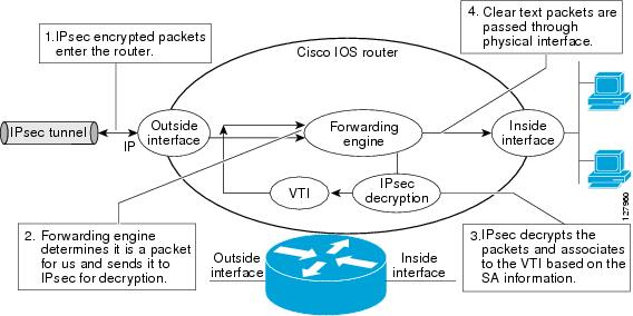
IPsec packet flow into the IPsec tunnel is illustrated in the figure below.

After packets arrive on the inside interface, the forwarding engine switches the packets to the VTI, where they are encrypted. The encrypted packets are handed back to the forwarding engine, where they are switched through the outside interface.
The figue below shows the packet flow out of the IPsec tunnel.
Multi-SA Support for Dynamic Virtual Tunnel Interfaces for IKEv1
DVTI supports multiple IPsec SAs. The DVTI can accept multiple IPsec selectors that are proposed by the initiator.
The DVTIs allow per peer features to be applied on a dedicated interface. You can order features in such way that all features that are applied on the virtual access interfaces are applied before applying crypto. Additionally, all the features that are applied on the physical interfaces are applied after applying crypto. Clean routing is available across all VRFs so that there are no traffic leaks from one VRF to another before encrypting.
Multi-SA VTIs ensure interoperation with third-party devices and provide a flexible, clean, and modular feature set.
Multi-SA VTIs enable a clean Cisco IOS infrastructure, even when the Cisco IOS software interoperates with third-party devices that implement only crypto maps.
VRF and Scalability of the Baseline Configuration for IKEv1
Virtual access instances inherit the Inside-VRF (IVRF) from the template configuration. Users must configure several templates to enforce an appropriate IVRF for each customer. The number of templates must be equal to the number of customers connecting to the headend. Such a configuration is cumbersome and undesirable.
This complication can be avoided by allowing the IKE profile to override the virtual access VRF with the VRF configured on the IKE profile. An even better solution will be to allow the IKE profile to override the virtual access VRF using AAA, but this method is supported only for IKEv2.
This complication can be avoided by allowing the IKE profile to override the virtual access VRF with the VRF configured on the IKE profile. A better solution is to allow the IKE profile to override the virtual access VRF using AAA, but this method is supported only for IKEv2.
The VRF configured in the ISAKMP profile is applied to the virtual access first. Then the configuration from virtual template is applied to the virtual access. If your virtual template contains ip vrf forwarding command configuration, the VRF from the template overrides the VRF from the ISAKMP profile.
Rules for Initial Configuration of a VRF
The following rules must be applied during the initial configuration of VRF:
- If you configure IVRF in the IKE profile without configuring it in the virtual template, then you must apply the VRF from the IKE profile on each virtual access derived from this IKE profile.
- If you configure VRF in an IKE profile and virtual template, then the virtual template IVRF gets precedence.
Rules for Changing the VRF
If you change the VRF configured in an IKE profile, all the IKE SAs, IPsec SAs, and the virtual access identifier derived from this profile will get deleted. The same rule applies when the VRF is configured on the IKE profile for the first time.
Multi-SA Support for Dynamic Virtual Tunnel Interfaces for IKEv2
The configuration of an IKEv2 profile in an IPsec profile on an IKEv2 responder is not mandatory. The IPSec DVTI sessions using the same virtual template can use different IKEv2 profiles, thus avoiding the need for a separate virtual template for each DVTI session that needs a different IKEv2 profile. Such an arrangement helps reduce the configuration size and save virtual template Interface Descriptor Block (IDB).
The IKEv2 authorization policy, which is a container of IKEv2 local AAA group authorization parameters, contains an AAA attribute AAA_AT_IPSEC_FLOW_LIMIT and theipsec flow- limit command. This attribute limits the number of IPsec flows that can terminate on an IPSec DVTI virtual access interface.
The value specified by the ipsec flow- limit command from the AAA overrides the value set by the set security-policy limit command from the IPSec profile. Any change to the value set by the set security-policy limit command in the IPSec profile is not applied to the current session but is applied to subsequent sessions.
If the value set by the set security-policy limit command is overridden by AAA, then the value from the IPSec profile is ignored, and any change to the value set by the set security-policy limit command in the IPSec profile does not affect the virtual access.
VRF and Scalability of Baseline Configuration for IKEv2
The IKEv2 multi-SA does not allow simultaneous configuration of a VRF and a template on the IKEv2 profile. Instead, the VRF can be configured on AAA and applied to the virtual access interface at the time of its creation.
You can use the AAA attribute INTERFACE_CONFIG to specify the ip vrf forwarding, ip unnumbered commands, and other interface configuration mode commands that are applied on the virtual access interface.
Note | If you override VRF using AAA, you must also specify the ip unnumbered command using AAA because the ip vrf forwarding command removes the ip unnumbered command configuration from the interface. |
Dynamic Virtual Tunnel Interface Life Cycle
IPsec profiles define policy for DVTIs. The dynamic interface is created at the end of IKE Phase 1 and IKE Phase 1.5. The interface is deleted when the IPsec session to the peer is closed. The IPsec session is closed when both IKE and IPsec SAs to the peer are deleted.
Routing with IPsec Virtual Tunnel Interfaces
Because VTIs are routable interfaces, routing plays an important role in the encryption process. Traffic is encrypted only if it is forwarded out of the VTI, and traffic arriving on the VTI is decrypted and routed accordingly. VTIs allow you to establish an encryption tunnel using a real interface as the tunnel endpoint. You can route to the interface or apply services such as QoS, firewalls, network address translation, and NetFlow statistics as you would to any other interface. You can monitor the interface and route to it, and it has an advantage over crypto maps because it is a real interface and provides the benefits of any other Cisco IOS interface.
How to Configure IPsec Virtual Tunnel Interface
- Configuring Static IPsec Virtual Tunnel Interfaces
- Configuring Dynamic IPsec Virtual Tunnel Interfaces
- Configuring Multi-SA Support for Dynamic Virtual Tunnel Interfaces Using IKEv1
- Configuring Multi-SA Support for Dynamic Virtual Tunnel Interfaces Using IKEv2
Configuring Static IPsec Virtual Tunnel Interfaces
DETAILED STEPS
Configuring Dynamic IPsec Virtual Tunnel Interfaces
DETAILED STEPS
Configuring Multi-SA Support for Dynamic Virtual Tunnel Interfaces Using IKEv1
DETAILED STEPS
Configuring Multi-SA Support for Dynamic Virtual Tunnel Interfaces Using IKEv2
Perform the following tasks to configure Multi-SA for DVTIs using IKEv2
- Defining an AAA Attribute List
- Configuring the VRF
- Configuring Internet Key Exchange Version 2 (IKEv2)
- Configuring an IPsec Profile and a Virtual Template
Defining an AAA Attribute List
DETAILED STEPS
Configuring the VRF
DETAILED STEPS
Configuring Internet Key Exchange Version 2 (IKEv2)
- Configuring the IKEv2 Proposal
- Configuring the IKEv2 Policy
- Configuring the IKEv2 Keyring
- Configuring the IKEv2 Profile
Configuring the IKEv2 Proposal
Note | The default IKEv2 proposal is used in the default IKEv2 policy. |
Perform this task to configure the proposals manually if you do not want to use the default proposal. The default IKEv2 proposal requires no configuration and is a collection of commonly used transforms types, which are as follows:
crypto ikev2 proposal default
encryption aes-cbc-256 aes-cbc-192 aes-cbc-128
integrity sha512 sha384 sha256 sha1 md5
group 2 5
The various crypto algorithms depend on the crypto engine. Some platforms support a particular crypto algorithm. To derive the default proposal, the following order of preference is used (left to right)
Encryption : aes-cbc-256 , aes-cbc-192, aes-cbc-128
Integrity : sha512, sha384, sha256, sha1, md5
DETAILED STEPS
Configuring the IKEv2 Policy
Note | Use the show crypto ikev2 policy command to display the IKEv2 default policy. |
Perform this task to manually create an IKEv2 policy; otherwise, the default proposal associated with the default policy is used for negotiation. An IKEv2 policy with no proposal is considered incomplete. During the initial exchange, the local address (IPv4 or IPv6) and the FVRF of the negotiating SA is matched with the policy and the proposal is selected.
DETAILED STEPS
Configuring the IKEv2 Keyring
Perform this task to configure the IKEv2 keyring if the local or remote authentication method is a preshared key.
IKEv2 keyring keys must be configured in the peer configuration submode that defines a peer subblock. An IKEv2 keyring can have multiple peer subblocks. A peer subblock contains a single symmetric or asymmetric key pair for a peer or peer group identified by any combination of hostname, identity, and IP address.
DETAILED STEPS
| Command or Action | Purpose | |||
|---|---|---|---|---|
Step 1 |
enable
Example: Router> enable |
Enables privileged EXEC mode. | ||
Step 2 |
configure
terminal
Example: Router# configure terminal |
Enters global configuration mode. | ||
Step 3 |
crypto
ikev2
keyring
keyring-name
Example: Router(config)# crypto ikev2 keyring kyr1 |
Defines an IKEv2 keyring and enters IKEv2 keyring configuration mode. | ||
Step 4 |
peer
name
Example: Router(config-ikev2-keyring)# peer peer1 |
Defines the peer or peer group and enters IKEv2 keyring peer configuration mode. | ||
Step 5 |
description
line-of-description
Example: Router(config-ikev2-keyring-peer)# description this is the first peer |
(Optional) Describes the peer or peer group. | ||
Step 6 |
hostname
name
Example: Router(config-ikev2-keyring-peer)# peer peer1 |
Specifies the peer using a hostname. | ||
Step 7 |
address
{ipv4-address [mask] |
ipv6-address
prefix}
Example: Router(config-ikev2-keyring-peer)# address 10.0.0.1 255.255.255.0 |
Specifies an IPv4 or IPv6 address or range for the peer.
| ||
Step 8 |
identity
{address {ipv4-address
|
ipv6-address} |
fqdn
name |
email
email-id |
key-id
key-id}
Example: Router(config-ikev2-keyring-peer)# identity address 10.0.0.5 |
Identifies the IKEv2 peer through the following identities:
| ||
Step 9 |
pre-shared-key
{local |
remote} {0 |
6 |
line}
Example: Router(config-ikev2-keyring-peer)# pre-shared-key local key1 |
Specifies the preshared key for the peer. | ||
Step 10 |
end
Example: Router(config-ikev2-keyring-peer)# end |
Exits IKEv2 keyring peer configuration mode and returns to privileged EXEC mode. |
Configuring the IKEv2 Profile
An IKEv2 profile is a repository of nonnegotiable parameters of the IKE SA (such as local/remote identities and authentication methods) and the services available to the authenticated peers that match the profile. An IKEv2 profile must be configured and must be attached to either a crypto map or an IPSec profile on the IKEv2 initiator. Use the command set ikev2-profile profile-name to attach the profile.
Perform this task to configure an IKEv2 profile.
Use the show crypto ikev2 profile tag command to display the IKEv2 profile.
DETAILED STEPS
| Command or Action | Purpose | |||
|---|---|---|---|---|
Step 1 |
enable
Example: Router> enable |
Enables privileged EXEC mode. | ||
Step 2 |
configure
terminal
Example: Router# configure terminal |
Enters global configuration mode. | ||
Step 3 |
crypto ikev2 profile
profile-name
Example: Router(config)# crypto ikev2 profile profile1 |
Defines an IKEv2 profile name and enters IKEv2 profile configuration mode. | ||
Step 4 |
description
line-of-description
Example: Router(config-ikev2-profile)# description this is the an IKEv2 profile |
(Optional) Describes the profile. | ||
Step 5 |
aaa
accounting
[psk |
cert |
eap]
list-name
Example: Router(config-ikev2-profile)# aaa accounting eap list1 |
(Optional) Enables AAA accounting for IPsec sessions.
| ||
Step 6 |
aaa
authentication
eap
list-name
Example: Router(config-ikev2-profile)# aaa authentication eap list1 |
(Optional) Specifies AAA authentication list for EAP authentication when implementing the IKEv2 remote access server. | ||
Step 7 |
authentication
{local {rsa-sig |
pre-share |
ecdsa-sig} |
remote {eap [query-identity] |
rsa-sig |
pre-share |
ecdsa-sig}
Example: Router(config-ikev2-profile)# authentication local ecdsa-sig |
Specifies the local or remote authentication method.
| ||
Step 8 |
aaa
authorization
{group |
user} [cert |
eap |
psk]
aaa-listname {aaa-username |
name-mangler
mangler-name}
Example: Router(config-ikev2-profile)# aaa authorization group list1 cert abc name-mangler mangler1 |
Specifies an AAA method list and username for group or user authorization when implementing the IKEv2 remote access server.
| ||
Step 9 | config-mode set
Example: Router(config-ikev2-profile)# config-mode set | (Optional) Enables sending the configuration mode set. The acceptance of config mode set is enabled by default. | ||
Step 10 |
dpd
interval
retry-interval {on-demand |
periodic}
Example: Router(config-ikev2-profile)# dpd 1000 250 periodic |
(Optional) Verifies that the IKE is live on the peers. | ||
Step 11 |
identity
local
{address
{ipv4-address |
ipv6-address} |
dn |
email
email-string |
fqdn
fqdn-string |
key-id
opaque-string}
Example: Router(config-ikev2-profile)# identity local email abc@example.com |
(Optional) Specifies the local IKEv2 identity type.
| ||
Step 12 |
ivrf
name
Example: Router(config-ikev2-profile)# ivrf vrf1 |
(Optional) Specifies a user-defined VRF or global VRF, if an IKEv2 profile is attached to a crypto map. The inside VRF (IVRF) for the tunnel interface should be configured on the tunnel interface.
| ||
Step 13 |
keyring [aaa]
name
Example: Router(config-ikev2-profile)# keyring keyring1 |
Specifies the local or AAA-based keyring that must be used with the local and remote preshared key authentication method.
| ||
Step 14 |
lifetime
seconds
Example: Router(config-ikev2-profile)# lifetime 10 |
Specifies the lifetime in seconds for the IKEv2 security association. | ||
Step 15 |
match
{address
local {ipv4-address |
ipv6-address} |
interface
name } |
certificate
certificate-map |
fvrf {fvrf-name |
any} |
identity
remote {address {ipv4-address [mask] |
ipv6-address
prefix} |
email [domain]
string |
fqdn [domain]
string |
key-id
opaque-string}
Example: Router(config-ikev2-profile)# match address local interface Ethernet 2/0 |
Use the match statements to select an IKEv2 profile for a peer:
| ||
Step 16 |
nat
keepalive
seconds
Example: Router(config-ikev2-profile)# nat keepalive 500 |
(Optional) Enables NAT keepalive and specifies the duration. | ||
Step 17 |
pki
trustpoint
trustpoint-label [sign |
verify]
Example: Router(config-ikev2-profile)# pki trustpoint tsp1 sign |
Specifies the trustpoints for use with the RSA signature authentication method as follows:
| ||
Step 18 |
virtual-template
number
Example: Router(config-ikev2-profile)# virtual-template 125 |
(Optional) Specifies the virtual template for cloning a virtual access interface. | ||
Step 19 |
end
Example: Router(config-ikev2-profile)# end |
Exits IKEv2 profile configuration mode and returns to privileged EXEC mode. |
Configuring an IPsec Profile and a Virtual Template
DETAILED STEPS
| Command or Action | Purpose | |
|---|---|---|
Step 1 |
enable
Example: Router> enable |
Enables privileged EXEC mode. |
Step 2 | configure terminal
Example: Router# configure terminal | Enters global configuration mode. |
Step 3 | cryptoipsectransform-setcisco-ipsec-profile
Example: Router(config)# crypto ikev2 profile cisco-ikev2-profile-100-1 |
Defines a transform set, and enters crypto transform configuration mode. |
Step 4 | exit
Example: Router(cfg-crypto-trans)# exit |
Exits crypto transform configuration mode, and enters global configuration mode. |
Step 5 | crypto ipsec
profile
name
Example: Router(config)# crypto ipsec profile cisco-ipsec-profile |
Defines the IPsec parameters used for IPsec encryption between two IPsec routers, and enters IPsec profile configuration mode. |
Step 6 | settransform-set
transform-set-name
Example: Router(ipsec-profile)# set transform-set tset |
Specifies which transform sets can be used with the crypto map entry. |
Step 7 | set
reverse-routedistancenumber
Example: Router(ipsec-profile)# set reverse-route distance 10 |
Defines a distance metric for the static routes. |
Step 8 | set
reverse-routetagtag-id
Example: Router(ipsec-profile)# set reverse-route tag 321 |
Tags a reverse route injection (RRI)-created route. |
Step 9 | exit
Example: Router(ipsec-profile)# exit |
Exits IPsec profile configuration mode, and returns to global configuration mode. |
Step 10 |
interface
virtual-template
interface-numbertypetunnel
Example: Router(config)# interface virtual-template 1 type tunnel |
Defines a virtual-template tunnel interface and enters interface configuration mode. |
Step 11 | ip
unnumbered
typenumber
Example: Router(config-if)# ip unnumbered Ethernet 0/0 |
Enables IP processing on an interface without assigning an explicit IP address to the interface. |
Step 12 | tunnel
mode
ipsec
ipv4
Example: Router(config-if)# tunnel mode ipsec ipv4 |
Defines the mode for the tunnel. |
Step 13 | tunnel
protectionipsec
ipv4
Example: Router(config-if)# tunnel protection ipsec profile cisco-ipsec-profile |
Associates a tunnel interface with an IPsec profile. |
Step 14 | exit
Example: Router(config-if)# exit |
Exits interface configuration mode and enters privileged EXEC mode. |
Configuration Examples for IPsec Virtual Tunnel Interface
- Example: Static Virtual Tunnel Interface with IPsec
- Example: VRF-Aware Static Virtual Tunnel Interface
- Example: Static Virtual Tunnel Interface with QoS
- Example: Static Virtual Tunnel Interface with Virtual Firewall
- Example: Dynamic Virtual Tunnel Interface Easy VPN Server
- Example: Dynamic Virtual Tunnel Interface Easy VPN Client
- Example: VRF-Aware IPsec with a Dynamic VTI When VRF is Configured Under a Virtual Template
- Example: VRF-Aware IPsec with Dynamic VTI When VRF is Configured Under a Virtual Template with the Gateway Option in an IPsec Profile
- Example: VRF-Aware IPsec with a Dynamic VTI When VRF is Configured Under an ISAKMP Profile
- Example: VRF-Aware IPsec with a Dynamic VTI When VRF is Configured Under an ISAKMP Profile and a Gateway Option in an IPsec Profile
- Example: VRF-Aware IPsec with a Dynamic VTI When a VRF is Configured Under Both a Virtual Template and an ISAKMP Profile
- Example: Configuring Multi-SA Support for Dynamic VTI Using IKEv2
- Example: Dynamic Virtual Tunnel Interface with Virtual Firewall
- Example: Dynamic Virtual Tunnel Interface with QoS
- Example: Dynamic Virtual Tunnel Interface Using GRE with IPsec Protection
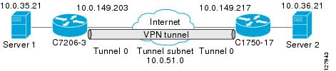
Example: Static Virtual Tunnel Interface with IPsec
The following example configuration uses a preshared key for authentication between peers. VPN traffic is forwarded to the IPsec VTI for encryption and then sent out the physical interface. The tunnel on subnet 10 checks packets for IPsec policy and passes them to the Crypto Engine (CE) for IPsec encapsulation. The figure below illustrates the IPsec VTI configuration.
Cisco 7206 Router Configuration
version 12.3
service timestamps debug datetime
service timestamps log datetime
hostname 7200-3
no aaa new-model
ip subnet-zero
ip cef
controller ISA 6/1
!
crypto isakmp policy 1
encr 3des
authentication pre-share
group 2
crypto isakmp key Cisco12345 address 0.0.0.0 0.0.0.0
crypto ipsec transform-set T1 esp-3des esp-sha-hmac
crypto ipsec profile P1
set transform-set T1
!
interface Tunnel0
 ip address 10.0.51.203 255.255.255.0
 ip ospf mtu-ignore
 load-interval 30
 tunnel source 10.0.149.203
 tunnel destination 10.0.149.217
 tunnel mode IPsec ipv4
 tunnel protection IPsec profile P1
!
interface Ethernet3/0
 ip address 10.0.149.203 255.255.255.0
 duplex full
!
interface Ethernet3/3
 ip address 10.0.35.203 255.255.255.0
 duplex full
!
ip classless
ip route 10.0.36.0 255.255.255.0 Tunnel0
line con 0
line aux 0
line vty 0 4
end
Cisco 1750 Router Configuration
version 12.3
hostname c1750-17
no aaa new-model
ip subnet-zero
ip cef
crypto isakmp policy 1
encr 3des
authentication pre-share
group 2
crypto isakmp key Cisco12345 address 0.0.0.0 0.0.0.0
crypto ipsec transform-set T1 esp-3des esp-sha-hmac
crypto ipsec profile P1
set transform-set T1
!
interface Tunnel0
 ip address 10.0.51.217 255.255.255.0
 ip ospf mtu-ignore
 tunnel source 10.0.149.217
 tunnel destination 10.0.149.203
 tunnel mode ipsec ipv4
 tunnel protection ipsec profile P1
!
interface FastEthernet0/0
 ip address 10.0.149.217 255.255.255.0
 speed 100
 full-duplex
!
interface Ethernet1/0
 ip address 10.0.36.217 255.255.255.0
 load-interval 30
 full-duplex
!
ip classless
ip route 10.0.35.0 255.255.255.0 Tunnel0
line con 0
line aux 0
line vty 0 4
end
Example: Verifying the Results for the IPsec Static Virtual Tunnel Interface
This section provides information that you can use to confirm that your configuration is working properly. In this display, Tunnel 0 is "up," and the line protocol is "up." If the line protocol is "down," the session is not active.
Verifying the Cisco 7206 Status
Router# show interface tunnel 0
Tunnel0 is up, line protocol is up
Hardware is Tunnel
Internet address is 10.0.51.203/24
MTU 1514 bytes, BW 9 Kbit, DLY 500000 usec,
reliability 255/255, txload 103/255, rxload 110/255
Encapsulation TUNNEL, loopback not set
Keepalive not set
Tunnel source 10.0.149.203, destination 10.0.149.217
Tunnel protocol/transport ipsec/ip
, key disabled, sequencing disabled
Tunnel TTL 255
Checksumming of packets disabled, fast tunneling enabled
Tunnel transmit bandwidth 8000 (kbps)
Tunnel receive bandwidth 8000 (kbps)
Tunnel protection via IPsec (profile "P1")
Last input never, output never, output hang never
Last clearing of "show interface" counters never
Input queue: 1/75/0/0 (size/max/drops/flushes); Total output drops: 0
Queueing strategy: fifo
Output queue: 0/0 (size/max)
30 second input rate 13000 bits/sec, 34 packets/sec
30 second output rate 36000 bits/sec, 34 packets/sec
191320 packets input, 30129126 bytes, 0 no buffer
Received 0 broadcasts, 0 runts, 0 giants, 0 throttles
0 input errors, 0 CRC, 0 frame, 0 overrun, 0 ignored, 0 abort
59968 packets output, 15369696 bytes, 0 underruns
0 output errors, 0 collisions, 0 interface resets
0 output buffer failures, 0 output buffers swapped out
Router# show crypto session
Crypto session current status
Interface: Tunnel0
Session status: UP-ACTIVE
Peer: 10.0.149.217 port 500
IKE SA: local 10.0.149.203/500 remote 10.0.149.217/500 Active
IPsec FLOW: permit ip 0.0.0.0/0.0.0.0 0.0.0.0/0.0.0.0
Active SAs: 4, origin: crypto map
Router# show ip route
Codes: C - connected, S - static, R - RIP, M - mobile, B - BGP
D - EIGRP, EX - EIGRP external, O - OSPF, IA - OSPF inter area
N1 - OSPF NSSA external type 1, N2 - OSPF NSSA external type 2
E1 - OSPF external type 1, E2 - OSPF external type 2
i - IS-IS, su - IS-IS summary, L1 - IS-IS level-1, L2 - IS-IS level-2
ia - IS-IS inter area, * - candidate default, U - per-user static route
o - ODR, P - periodic downloaded static route
Gateway of last resort is not set
10.0.0.0/8 is variably subnetted, 4 subnets, 2 masks
C 10.0.35.0/24 is directly connected, Ethernet3/3
S 10.0.36.0/24 is directly connected, Tunnel0
C 10.0.51.0/24 is directly connected, Tunnel0
C 10.0.149.0/24 is directly connected, Ethernet3/0
Example: VRF-Aware Static Virtual Tunnel Interface
To add VRF to the static VTI example, include the ipvrf and ip vrf forwarding commands to the configuration as shown in the following example.
Cisco 7206 Router Configuration
hostname cisco 7206
.
.
ip vrf sample-vti1
 rd 1:1
 route-target export 1:1
 route-target import 1:1
!
.
.
interface Tunnel0
 ip vrf forwarding sample-vti1
 ip address 10.0.51.217 255.255.255.0
 tunnel source 10.0.149.217
 tunnel destination 10.0.149.203
 tunnel mode ipsec ipv4
 tunnel protection ipsec profile P1
.
.
!
end
Example: Static Virtual Tunnel Interface with QoS
You can apply any QoS policy to the tunnel endpoint by including the service-policy statement under the tunnel interface. The following example is policing traffic out the tunnel interface.
Cisco 7206 Router Configuration
hostname cisco 7206
.
.
class-map match-all VTI
 match any
!
policy-map VTI
  class VTI
  police cir 2000000
    conform-action transmit
    exceed-action drop
!
.
.
interface Tunnel0
 ip address 10.0.51.217 255.255.255.0
 tunnel source 10.0.149.217
 tunnel destination 10.0.149.203
 tunnel mode ipsec ipv4
 tunnel protection ipsec profile P1
 service-policy output VTI
!
.
.
!
end
Example: Static Virtual Tunnel Interface with Virtual Firewall
Applying the virtual firewall to the SVTI tunnel allows traffic from the spoke to pass through the hub to reach the Internet. The figure below illustrates an SVTI with the spoke protected inherently by the corporate firewall.
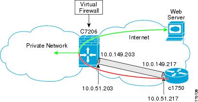
The basic SVTI configuration has been modified to include the virtual firewall definition:
Cisco 7206 Router Configuration
hostname cisco 7206
.
.
ip inspect max-incomplete high 1000000
ip inspect max-incomplete low 800000
ip inspect one-minute high 1000000
ip inspect one-minute low 800000
ip inspect tcp synwait-time 60
ip inspect tcp max-incomplete host 100000 block-time 2
ip inspect name IOSFW1 tcp timeout 300
ip inspect name IOSFW1 udp
!
.
.
interface GigabitEthernet0/1
 description Internet Connection
 ip address 172.18.143.246 255.255.255.0
 ip access-group 100 in
 ip nat outside
!
interface Tunnel0
 ip address 10.0.51.217 255.255.255.0
 ip nat inside
 ip inspect IOSFW1 in
 tunnel source 10.0.149.217
 tunnel destination 10.0.149.203
 tunnel mode ipsec ipv4
 tunnel protection ipsec profile P1
!
ip classless
ip route 0.0.0.0 0.0.0.0 172.18.143.1
!
ip nat translation timeout 120
ip nat translation finrst-timeout 2
ip nat translation max-entries 300000
ip nat pool test1 10.2.100.1 10.2.100.50 netmask 255.255.255.0
ip nat inside source list 110 pool test1 vrf test-vti1 overload
!
access-list 100 permit esp any any
access-list 100 permit udp any eq isakmp any
access-list 100 permit udp any eq non500-isakmp any
access-list 100 permit icmp any any
access-list 110 deny   esp any any
access-list 110 deny   udp any eq isakmp any
access-list 110 permit ip any any
access-list 110 deny   udp any eq non500-isakmp any
!
end
Example: Dynamic Virtual Tunnel Interface Easy VPN Server
The following example illustrates the use of the DVTI Easy VPN server, which serves as an IPsec remote access aggregator. The client can be a home user running a Cisco VPN client or it can be a Cisco IOS router configured as an Easy VPN client.
Cisco 7206 Router Configuration
hostname cisco 7206
!
aaa new-model
aaa authentication login local_list local
aaa authorization network local_list local
aaa session-id common
!
ip subnet-zero
ip cef
!
username cisco password 0 cisco123
!
controller ISA 1/1
!
crypto isakmp policy 1
 encr 3des
 authentication pre-share
 group 2
!
crypto isakmp client configuration group group1
 key cisco123
 pool group1pool
 save-password
!
crypto isakmp profile vpn1-ra
   match identity group group1
   client authentication list local_list
   isakmp authorization list local_list
   client configuration address respond
   virtual-template 1
!
crypto ipsec transform-set VTI-TS esp-3des esp-sha-hmac
!
crypto ipsec profile test-vti1
 set transform-set VTI-TS
!
interface GigabitEthernet0/1
 description Internet Connection
 ip address 172.18.143.246 255.255.255.0
!
interface GigabitEthernet0/2
 description Internal Network
 ip address 10.2.1.1 255.255.255.0
!
interface Virtual-Template1 type tunnel
 ip unnumbered GigabitEthernet0/1
 ip virtual-reassembly
 tunnel mode ipsec ipv4
 tunnel protection ipsec profile test-vti1
!
ip local pool group1pool 192.168.1.1 192.168.1.4
ip classless
ip route 0.0.0.0 0.0.0.0 172.18.143.1
!
end
Verifying the Results for the Dynamic Virtual Tunnel Interface Easy VPN Server Example
The following examples show that a DVTI has been configured for an Easy VPN server.
Router# show running-config interface Virtual-Access2
Building configuration...
Current configuration : 250 bytes
!
interface Virtual-Access2
 ip unnumbered GigabitEthernet0/1
 ip virtual-reassembly
 tunnel source 172.18.143.246
 tunnel destination 172.18.143.208
 tunnel mode ipsec ipv4
 tunnel protection ipsec profile test-vti1
 no tunnel protection ipsec initiate
end
Router# show ip route
Codes: C - connected, S - static, R - RIP, M - mobile, B - BGP
       D - EIGRP, EX - EIGRP external, O - OSPF, IA - OSPF inter area
       N1 - OSPF NSSA external type 1, N2 - OSPF NSSA external type 2
       E1 - OSPF external type 1, E2 - OSPF external type 2
       i - IS-IS, su - IS-IS summary, L1 - IS-IS level-1, L2 - IS-IS level-2
       ia - IS-IS inter area, * - candidate default, U - per-user static route
       o - ODR, P - periodic downloaded static route
Gateway of last resort is 10.2.1.10 to network 0.0.0.0
     172.18.0.0/24 is subnetted, 1 subnets
C       172.18.143.0 is directly connected, GigabitEthernet0/1
     192.168.1.0/32 is subnetted, 1 subnets
S       192.168.1.1 [1/0] via 0.0.0.0, Virtual-Access2
     10.0.0.0/24 is subnetted, 1 subnets
C       10.2.1.0 is directly connected, GigabitEthernet0/2
S*   0.0.0.0/0 [1/0] via 172.18.143.1
Example: Dynamic Virtual Tunnel Interface Easy VPN Client
The following example shows how you can set up a router as the Easy VPN client. This example uses basically the same idea as the Easy VPN client that you can run from a PC to connect. In fact, the configuration of the Easy VPN server will work for the software client or the Cisco IOS client.
hostname cisco 1841
!
no aaa new-model
!
ip cef
!
username cisco password 0 cisco123
!
crypto ipsec client ezvpn CLIENT
 connect manual
 group group1 key cisco123
 mode client
 peer 172.18.143.246
 virtual-interface 1
 username cisco password cisco123
 xauth userid mode local
!
interface Loopback0
 ip address 10.1.1.1 255.255.255.255
!
interface FastEthernet0/0
 description Internet Connection
 ip address 172.18.143.208 255.255.255.0
 crypto ipsec client ezvpn CLIENT
!
interface FastEthernet0/1
 ip address 10.1.1.252 255.255.255.0
 crypto ipsec client ezvpn CLIENT inside
!
interface Virtual-Template1 type tunnel
 ip unnumbered Loopback0
!
ip route 0.0.0.0 0.0.0.0 172.18.143.1 254
!
end
The client definition can be set up in many different ways. The mode specified with the connect command can be automatic or manual. If the connect mode is set to manual, the IPsec tunnel has to be initiated manually by a user.
Also note use of the mode command. The mode can be client, network-extension, or network-extension-plus. This example indicates client mode, which means that the client is given a private address from the server. Network-extension mode is different from client mode in that the client specifies for the server its attached private subnet. Depending on the mode, the routing table on either end will be slightly different. The basic operation of the IPSec tunnel remains the same, regardless of the specified mode.
Verifying the Results for the Dynamic Virtual Tunnel Interface Easy VPN Client Example
The following examples illustrate different ways to display the status of the DVTI.
Router# show running-config interface Virtual-Access2
Building configuration...
Current configuration : 148 bytes
!
interface Virtual-Access2
 ip unnumbered Loopback1
 tunnel source FastEthernet0/0
 tunnel destination 172.18.143.246
 tunnel mode ipsec ipv4
end
Router# show running-config interface Loopback1
Building configuration...
Current configuration : 65 bytes
!
interface Loopback1
 ip address 192.168.1.1 255.255.255.255
end
Router# show ip route
Codes: C - connected, S - static, R - RIP, M - mobile, B - BGP
       D - EIGRP, EX - EIGRP external, O - OSPF, IA - OSPF inter area
       N1 - OSPF NSSA external type 1, N2 - OSPF NSSA external type 2
       E1 - OSPF external type 1, E2 - OSPF external type 2
       i - IS-IS, su - IS-IS summary, L1 - IS-IS level-1, L2 - IS-IS level-2
       ia - IS-IS inter area, * - candidate default, U - per-user static route
       o - ODR, P - periodic downloaded static route
Gateway of last resort is 172.18.143.1 to network 0.0.0.0
     10.0.0.0/32 is subnetted, 1 subnets
C       10.1.1.1 is directly connected, Loopback0
     172.18.0.0/24 is subnetted, 1 subnets
C       172.18.143.0 is directly connected, FastEthernet0/0
     192.168.1.0/32 is subnetted, 1 subnets
C       192.168.1.1 is directly connected, Loopback1
S*   0.0.0.0/0 [1/0] via 0.0.0.0, Virtual-Access2
Router# show crypto ipsec client ezvpn
Easy VPN Remote Phase: 6
Tunnel name : CLIENT
Inside interface list: FastEthernet0/1
Outside interface: Virtual-Access2 (bound to FastEthernet0/0)
Current State: IPSEC_ACTIVE
Last Event: SOCKET_UP
Address: 192.168.1.1
Mask: 255.255.255.255
Save Password: Allowed
Current EzVPN Peer: 172.18.143.246
Example: VRF-Aware IPsec with a Dynamic VTI When VRF is Configured Under a Virtual Template
The following example shows how to configure VRF-aware IPsec under a virtual template to take advantage of the DVTI:
hostname cisco 7206
!
ip vrf VRF-100-1
  rd 1:1
!
ip vrf VRF-100-2
  rd 1:1
!
!
!
crypto keyring cisco-100-1
  pre-shared-key address 10.1.1.1 key cisco-100-1
crypto keyring cisco-100-2
  pre-shared-key address 10.1.2.1 key cisco-100-2
crypto isakmp profile cisco-isakmp-profile-100-1
  keyring cisco-100-1
  match identity address 10.1.1.0 255.255.255.0
  virtual-template 101
crypto isakmp profile cisco-isakmp-profile-100-2
  keyring cisco-100-2
  match identity address 10.1.2.0 255.255.255.0
  virtual-template 102
!
!
crypto ipsec transform-set cisco esp-3des esp-sha-hmac
!
crypto ipsec profile cisco-ipsec-profile-101
  set security-policy limit 3
  set transform-set cisco
!
crypto ipsec profile cisco-ipsec-profile-102
  set security-policy limit 5
  set transform-set Cisco
!
interface Virtual-Template101 type tunnel
  ip vrf forwarding VRF-100-1
  ip unnumbered Ethernet 0/0
  tunnel mode ipsec ipv4
  tunnel protection ipsec profile cisco-ipsec-profile-101
!
interface Virtual-Template102 type tunnel
  ip vrf forwarding VRF-100-2
  ip unnumbered Ethernet 0/0
  tunnel mode ipsec ipv4
  tunnel protection ipsec profile cisco-ipsec-profile-102
!
Example: VRF-Aware IPsec with Dynamic VTI When VRF is Configured Under a Virtual Template with the Gateway Option in an IPsec Profile
The following example shows how to configure VRF-aware IPsec to take advantage of the DVTI, when the VRF is configured under a virtual template with the gateway option in an IPsec profile:
hostname c7206
!
ip vrf VRF-100-1
  rd 1:1
!
ip vrf VRF-100-2
  rd 1:1
!
!
!
crypto keyring cisco-100-1
  pre-shared-key address 10.1.1.1 key cisco-100-1
crypto keyring cisco-100-2
  pre-shared-key address 10.1.2.1 key cisco-100-2
crypto isakmp profile cisco-isakmp-profile-100-1
  keyring cisco-100-1
  match identity address 10.1.1.0 255.255.255.0
  virtual-template 101
crypto isakmp profile cisco-isakmp-profile-100-2
  keyring cisco-100-2
  match identity address 10.1.2.0 255.255.255.0
  virtual-template 102
!
!
crypto ipsec transform-set cisco esp-3des esp-sha-hmac
!
crypto ipsec profile cisco-ipsec-profile-101
  set security-policy limit 3
  set transform-set cisco
  set reverse-route gateway 50.0.0.1
!
crypto ipsec profile cisco-ipsec-profile-102
  set security-policy limit 5
  set transform-set cisco
  set reverse-route gateway 50.0.0.1
!
interface Virtual-Template101 type tunnel
  ip vrf forwarding VRF-100-1
  ip unnumbered Ethernet 0/0
  tunnel mode ipsec ipv4
  tunnel protection ipsec profile cisco-ipsec-profile-101
!
interface Virtual-Template102 type tunnel
  ip vrf forwarding VRF-100-2
  ip unnumbered Ethernet 0/0
  tunnel mode ipsec ipv4
 tunnel protection ipsec profile cisco-ipsec-profile-102
!
Example: VRF-Aware IPsec with a Dynamic VTI When VRF is Configured Under an ISAKMP Profile
hostname cisco 7206
!
ip vrf VRF-100-1
  rd 1:1
!
ip vrf VRF-100-2
  rd 1:1
!
crypto keyring cisco-100-1
  pre-shared-key address 10.1.1.1 key cisco-100-1
crypto keyring cisco-100-2
  pre-shared-key address 10.1.2.1 key cisco-100-2
crypto isakmp profile cisco-isakmp-profile-100-1
  vrf VRF-100-1
  keyring cisco-100-1
  match identity address 10.1.1.0 255.255.255.0
  virtual-template 1
crypto isakmp profile cisco-isakmp-profile-100-2
  vrf VRF-100-2
  keyring cisco-100-2
  match identity address 10.1.2.0 255.255.255.0
  virtual-template 1
!
!
crypto ipsec transform-set cisco esp-3des esp-sha-hmac
crypto ipsec profile cisco-ipsec-profile
  set security-policy limit 3
  set transform-set cisco
!
!
!
interface Virtual-Template 1 type tunnel
  ip unnumbered ethernet 0/0
  tunnel mode ipsec ipv4
  tunnel protection ipsec profile cisco-ipsec-profile
!
!
Example: VRF-Aware IPsec with a Dynamic VTI When VRF is Configured Under an ISAKMP Profile and a Gateway Option in an IPsec Profile
The following example shows how to configure VRF-aware IPsec to take advantage of the DVTI when the VRF is configured under an ISAKMP profile and a gateway option is in an IPsec profile:
hostname cisco 7206
!
ip vrf VRF-100-1
		rd 1:1
!
ip vrf VRF-100-2
		rd 1:1
!
crypto keyring cisco-100-1
		pre-shared-key address 10.1.1.1 key cisco-100-1
crypto keyring cisco-100-2
		pre-shared-key address 10.1.2.1 key cisco-100-2
crypto isakmp profile cisco-isakmp-profile-100-1
		vrf VRF-100-1
		keyring cisco-100-1
		match identity address 10.1.1.0 255.255.255.0
		virtual-template 1
crypto isakmp profile cisco-isakmp-profile-100-2
		vrf VRF-100-2
		keyring cisco-100-2
		match identity address 10.1.2.0 255.255.255.0
		virtual-template 1
!
!
crypto ipsec transform-set cisco esp-3des esp-sha-hmac
crypto ipsec profile cisco-ipsec-profile
		set security-policy limit 3
		set transform-set cisco
		set reverse-route gateway 50.0.0.1
!
!
!
interface Virtual-Template1 type tunnel
		ip unnumbered Ethernet0/0
		tunnel mode ipsec ipv4
		tunnel protection ipsec profile cisco-ipsec-profile
Example: VRF-Aware IPsec with a Dynamic VTI When a VRF is Configured Under Both a Virtual Template and an ISAKMP Profile
Note | When separate VRFs are configured under an ISAKMP profile and a virtual template, the VRF configured under the virtual template takes precedence. This configuration is not recommended. |
The following example shows how to configure VRF-aware IPsec to take advantage of the DVTI when the VRF is configured under both a virtual template and an ISAKMP profile:
hostname cisco 7206
.       .
.
ip vrf test-vti2
rd 1:2
route-target export 1:1
route-target import 1:1
!
.
.
.
ip vrf test-vti1
rd 1:1
route-target export 1:1
route-target import 1:1
!
.
.
.
crypto isakmp profile cisco-isakmp-profile
		vrf test-vti2
		keyring key
		match identity address 10.1.1.0 255.255.255.0
!
.
.
.
interface Virtual-Template1 type tunnel
ip vrf forwarding test-vti1
ip unnumbered Loopback0
ip virtual-reassembly
tunnel mode ipsec ipv4
tunnel protection ipsec profile test-vti1
!
.
.
.
end
Example: Configuring Multi-SA Support for Dynamic VTI Using IKEv2
The following examples show how to configure Multi-SA Support for Dynamic VTI using IKEv2:
!
!
aaa new-model
!
!
aaa authorization network grp-list local
!
aaa attribute list aaa-cisco-ikev2-profile-100-1
attribute type interface-config "ip vrf forwarding VRF-100-1"
attribute type interface-config "ip unnumbered Ethernet0/0"
!
aaa attribute list aaa-cisco-ikev2-profile-100-2
attribute type interface-config "ip vrf forwarding VRF-100-2"
attribute type interface-config "ip unnumbered Ethernet0/0"
!
aaa attribute list aaa-cisco-ikev2-profile-100-3
attribute type interface-config "ip vrf forwarding VRF-100-3"
attribute type interface-config "ip unnumbered Ethernet0/0"
!
!
!
!
!
aaa session-id common
!
ip vrf VRF-100-1
rd 101:1
 route-target export 101:1
 route-target import 101:1
!
ip vrf VRF-100-2
rd 102:2
route-target export 102:2
route-target import 102:2
!
ip vrf VRF-100-3
rd 103:3
route-target export 103:3
route-target import 103:3
!
!
!
crypto ikev2 authorization policy auth-policy-cisco-ikev2-profile-100-1
aaa attribute list aaa-cisco-ikev2-profile-100-1
ipsec flow-limit 3
!
crypto ikev2 authorization policy auth-policy-cisco-ikev2-profile-100-2
aaa attribute list aaa-cisco-ikev2-profile-100-2
ipsec flow-limit 3
!
crypto ikev2 authorization policy auth-policy-cisco-ikev2-profile-100-3
aaa attribute list aaa-cisco-ikev2-profile-100-3
ipsec flow-limit 3
!
crypto ikev2 proposal ikev2-proposal
encryption 3des
integrity md5
group 2
!
crypto ikev2 policy ikev2-policy
match fvrf any
proposal ikev2-proposal
!
crypto ikev2 keyring cisco-ikev2
peer cisco-100-1
 address 100.1.1.1
 pre-shared-key cisco-100-1
!
peer cisco-100-2
address 100.1.2.1
pre-shared-key cisco-100-2
!
peer cisco-100-3
address 100.1.3.1
pre-shared-key cisco-100-3
!
!
!
crypto ikev2 profile cisco-ikev2-profile-100-1
match fvrf any
match identity remote address 10.1.1.1 255.255.255.255
authentication local pre-share
authentication remote pre-share
keyring cisco-ikev2
aaa authorization group grp-list auth-policy-cisco-ikev2-profile-100-1
virtual-template 1
!
crypto ikev2 profile cisco-ikev2-profile-100-2
match fvrf any
match identity remote address 10.1.2.1 255.255.255.255
authentication local pre-share
authentication remote pre-share
keyring cisco-ikev2
aaa authorization group group-list auth-policy-cisco-ikev2-profile-100-2
virtual-template 1
!
crypto ikev2 profile cisco-ikev2-profile-100-3
match fvrf any
match identity remote address 10.1.3.1 255.255.255.255
authentication local pre-share
authentication remote pre-share
keyring cisco-ikev2
aaa authorization group group-list auth-policy-cisco-ikev2-profile-100-3
virtual-template 1
!
!
crypto ipsec transform-set cisco esp-3des esp-sha-hmac
!
crypto ipsec profile cisco-ipsec-profile
set transform-set cisco
set reverse-route distance 10
set reverse-route tag 321
interface Virtual-Template1 type tunnel
ip unnumbered Ethernet0/0
tunnel mode ipsec ipv4
tunnel protection ipsec profile cisco-ipsec-profile
!
Example: Dynamic Virtual Tunnel Interface with Virtual Firewall
The DVTI Easy VPN server can be configured behind a virtual firewall. Behind-the-firewall configuration allows users to enter the network, while the network firewall is protected from unauthorized access. The virtual firewall uses Context-Based Access Control (CBAC) and NAT applied to the Internet interface as well as to the virtual template.
hostname cisco 7206
.
.
ip inspect max-incomplete high 1000000
ip inspect max-incomplete low 800000
ip inspect one-minute high 1000000
ip inspect one-minute low 800000
ip inspect tcp synwait-time 60
ip inspect tcp max-incomplete host 100000 block-time 2
ip inspect name IOSFW1 tcp timeout 300
ip inspect name IOSFW1 udp
!
.
.
interface GigabitEthernet0/1
 description Internet Connection
 ip address 172.18.143.246 255.255.255.0
 ip access-group 100 in
 ip nat outside
!
interface GigabitEthernet0/2
 description Internal Network
 ip address 10.2.1.1 255.255.255.0
!
interface Virtual-Template1 type tunnel
 ip unnumbered Loopback0
 ip nat inside
 ip inspect IOSFW1 in
 tunnel mode ipsec ipv4
 tunnel protection ipsec profile test-vti1
!
ip classless
ip route 0.0.0.0 0.0.0.0 172.18.143.1
!
ip nat translation timeout 120
ip nat translation finrst-timeout 2
ip nat translation max-entries 300000
ip nat pool test1 10.2.100.1 10.2.100.50 netmask 255.255.255.0
ip nat inside source list 110 pool test1 vrf test-vti1 overload
!
access-list 100 permit esp any any
access-list 100 permit udp any eq isakmp any
access-list 100 permit udp any eq non500-isakmp any
access-list 100 permit icmp any any
access-list 110 deny   esp any any
access-list 110 deny   udp any eq isakmp any
access-list 110 permit ip any any
access-list 110 deny   udp any eq non500-isakmp any
!
end
Example: Dynamic Virtual Tunnel Interface with QoS
You can add QoS to the DVTI tunnel by applying the service policy to the virtual template. When the template is cloned to make the virtual-access interface, the service policy will be applied there. The following example shows the basic DVTI configuration with QoS added.
hostname cisco 7206
.
.
class-map match-all VTI
 match any
!
policy-map VTI
  class VTI
  police cir 2000000
    conform-action transmit
    exceed-action drop
!
.
.
interface Virtual-Template1 type tunnel
 ip vrf forwarding test-vti1
 ip unnumbered Loopback0
 ip virtual-reassembly
 tunnel mode ipsec ipv4
 tunnel protection ipsec profile test-vti1
 service-policy output VTI
!
.
.
!
end
Example: Dynamic Virtual Tunnel Interface Using GRE with IPsec Protection
        Router1(config)# crypto ipsec transform-set 3DES esp-3des esp-sha-hmac
        Router1(cfg-crypto-trans)# mode transport
        Router1(cfg-crypto-trans)# exit
        Router1# config terminal
        Router1(config)# crypto ipsec profile 3des set transform-set 3DES
        Router1(config)# interface Tunnel1
        Router1(config-if)# description to-3800
        Router1(config-if)# ip address 172.29.0.137 255.255.255.252
        Router1(config-if)# tunnel source Ethernet0/0
        Router1(config-if)# tunnel destination 10.38.38.1
        Router1(config-if)# tunnel protection ipsec profile 3des
The show interface tunnel command verifies the tunnel interface configuration.
Note | The tunnel transport MTU accounts for IPsec encryption overhead with GRE when used with the above configuration. |
        router1# show interface tunnel 1

         Tunnel1 is up, line protocol is up
         Hardware is Tunnel
         Description: to-3800
         Internet address is 172.29.0.137/30
         MTU 17880 bytes, BW 100 Kbit/sec, DLY 50000 usec,
             reliability 255/255, txload 1/255, rxload 1/255
         Encapsulation TUNNEL, loopback not set
         Keepalive not set
         Tunnel source 10.39.39.1 (Ethernet0/0), destination 10.38.38.1
          Tunnel Subblocks:
             src-track:
                 Tunnel1 source tracking subblock associated with Ethernet0/0
                  Set of tunnels with source Ethernet0/0, 1 member (includes iterators), on interface <OK>
         Tunnel protocol/transport GRE/IP
             Key disabled, sequencing disabled
             Checksumming of packets disabled
         Tunnel TTL 255, Fast tunneling enabled
         Path MTU Discovery, ager 10 mins, min MTU 92
         Tunnel transport MTU 1440 bytes
Additional References
Related Documents
|
Related Topic |
Document Title |
|---|---|
|
IPsec, security issues |
Configuring Security for VPNs with IPsec |
|
QoS, configuring |
Cisco IOS Quality of Service Solutions Configuration Guide o n Cisco.com |
|
Cisco IOS commands |
|
|
Security commands |
Cisco IOS Security Command Reference |
|
VPN configuration |
|
MIBs
Technical Assistance
|
Description |
Link |
|---|---|
|
The Cisco Support and Documentation website provides online resources to download documentation, software, and tools. Use these resources to install and configure the software and to troubleshoot and resolve technical issues with Cisco products and technologies. Access to most tools on the Cisco Support and Documentation website requires a Cisco.com user ID and password. |
Feature Information for IPsec Virtual Tunnel Interface
The following table provides release information about the feature or features described in this module. This table lists only the software release that introduced support for a given feature in a given software release train. Unless noted otherwise, subsequent releases of that software release train also support that feature.
Use Cisco Feature Navigator to find information about platform support and Cisco software image support. To access Cisco Feature Navigator, go to www.cisco.com/go/cfn. An account on Cisco.com is not required.
| Table 1 | Feature Information for IPsec Virtual Tunnel Interface |
|
Feature Name |
Releases |
Feature Configuration Information |
|---|---|---|
| Dynamic IPsec VTIs | 12.3(7)T 12.3(14)T |
Dynamic VTIs provide efficiency in the use of IP addresses and provide secure connectivity. Dynamic VTIs allow dynamically downloadable per-group and per-user policies to be configured on a RADIUS server. The per-group or per-user definition can be created using Xauth User or Unity group, or it can be derived from a certificate. Dynamic VTIs are standards based, so interoperability in a multiple-vendor environment is supported. IPsec dynamic VTIs allow you to create highly secure connectivity for remote access VPNs and can be combined with Cisco Architecture for Voice, Video, and Integrated Data (AVVID) to deliver converged voice, video, and data over IP networks. The dynamic VTI simplifies VRF-aware IPsec deployment. The VRF is configured on the interface. The following commands were introduced or modified: crypto isakmp profile, interface virtual-template, show vtemplate, tunnel mode, virtual-template. |
|
Multi-SA for Dynamic VTIs |
15.2(1)T |
The DVTI can accept multiple IPsec selectors that are proposed by the initiator. The following commands were introduced or modified: set security-policy limit, set reverse-route. |
|
Static IPsec VTIs |
12.2(33)SRA 12.2(33)SXH 12.3(7)T 12.3(14)T |
IPsec VTIs provide a routable interface type for terminating IPsec tunnels and an easy way to define protection between sites to form an overlay network. IPsec VTIs simplify configuration of IPsec for protection of remote links, support multicast, and simplify network management and load balancing. |
Cisco and the Cisco logo are trademarks or registered trademarks of Cisco and/or its affiliates in the U.S. and other countries. To view a list of Cisco trademarks, go to this URL: www.cisco.com/go/trademarks. Third-party trademarks mentioned are the property of their respective owners. The use of the word partner does not imply a partnership relationship between Cisco and any other company. (1110R)
Any Internet Protocol (IP) addresses and phone numbers used in this document are not intended to be actual addresses and phone numbers. Any examples, command display output, network topology diagrams, and other figures included in the document are shown for illustrative purposes only. Any use of actual IP addresses or phone numbers in illustrative content is unintentional and coincidental.