
 Feedback
Contents
- Signalling Overview
- IP Precedence
- Resource Reservation Protocol
- How It Works
- RSVP Support for Low Latency Queueing
- Restrictions
- Prerequisites
- RSVP Support for Frame Relay
- RSVP Bandwidth Allocation and Modular QoS Command Line Interface (CLI)
- Admission Control
- Data Packet Classification
- Benefits
- Restrictions
- Prerequisites
- RSVP-ATM QoS Interworking
- How It Works
- An Example Scenario
- COPS for RSVP
- How It Works
- A Detailed Look at COPS for RSVP Functioning
- Subnetwork Bandwidth Manager
Signalling Overview
In the most general sense, QoS signalling is a form of network communication that allows an end station or network node to communicate with, or signal, its neighbors to request special handling of certain traffic. QoS signalling is useful for coordinating the traffic handling techniques provided by other QoS features. It plays a key role in configuring successful overall end-to-end QoS service across your network.
True end-to-end QoS requires that every element in the network path--switch, router, firewall, host, client, and so on--deliver its part of QoS, and that all of these entities be coordinated with QoS signalling.
Many viable QoS signalling solutions provide QoS at some places in the infrastructure; however, they often have limited scope across the network. To achieve end-to-end QoS, signalling must span the entire network.
Cisco IOS QoS software takes advantage of IP to meet the challenge of finding a robust QoS signalling solution that can operate over heterogeneous network infrastructures. It overlays Layer 2 technology-specific QoS signalling solutions with Layer 3 IP QoS signalling methods of the Resource Reservation Protocol (RSVP) and IP Precedence features.
An IP network can achieve end-to-end QoS, for example, by using part of the IP packet header to request special handling of priority or time-sensitive traffic. Given the ubiquity of IP, QoS signalling that takes advantage of IP provides powerful end-to-end signalling. Both RSVP and IP Precedence fit this category.
Either in-band (IP Precedence, 802.1p) or out-of-band (RSVP) signalling is used to indicate that a particular QoS is desired for a particular traffic classification. IP Precedence signals for differentiated QoS, and RSVP for guaranteed QoS.
IP Precedence
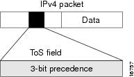
As shown in the figure below, the IP Precedence feature utilizes the three precedence bits in the type of service (ToS) field of the IP version 4 (IPv4) header to specify class of service for each packet. You can partition traffic in up to six classes of service using IP precedence. The queueing technologies throughout the network can then use this signal to provide the appropriate expedited handling.
You can use features such as policy-based routing (PBR) and committed access rate (CAR) to set precedence based on extended access list classification. Use of these features allows considerable flexibility of precedence assignment, including assignment by application or user, or by destination or source subnet. Typically, you deploy these features as close to the edge of the network or the administrative domain as possible, so that each subsequent network element can provide service based on the determined policy. IP precedence can also be set in the host or the network client; however, IP precedence can be overridden by policy within the network.
IP precedence enables service classes to be established using existing network queueing mechanisms, such as weighted fair queueing (WFQ) and Weighted Random Early Detection (WRED), with no changes to existing applications and with no complicated network requirements.
Resource Reservation Protocol
RSVP is the first significant industry-standard protocol for dynamically setting up end-to-end QoS across a heterogeneous network. RSVP, which runs over IP, allows an application to dynamically reserve network bandwidth. Using RSVP, applications can request a certain level of QoS for a data flow across a network.
The Cisco IOS QoS implementation allows RSVP to be initiated within the network using configured proxy RSVP. Using this capability, you can take advantage of the benefits of RSVP in the network even for non-RSVP enabled applications and hosts. RSVP is the only standard signalling protocol designed to guarantee network bandwidth from end-to-end for IP networks.
RSVP does not perform its own routing; instead it uses underlying routing protocols to determine where it should carry reservation requests. As routing changes paths to adapt to topology changes, RSVP adapts its reservation to the new paths wherever reservations are in place. This modularity does not prevent RSVP from using other routing services. RSVP provides transparent operation through router nodes that do not support RSVP.
RSVP works in conjunction with, not in place of, current queueing mechanisms. RSVP requests the particular QoS, but it is up to the particular interface queueing mechanism, such as WFQ or WRED, to implement the reservation.
You can use RSVP to make two types of dynamic reservations: controlled load and guaranteed rate services, both of which are briefly described in the chapter "Quality of Service Overview" in this book.
A primary feature of RSVP is its scalability. RSVP scales well using the inherent scalability of multicast. RSVP scales to very large multicast groups because it uses receiver-oriented reservation requests that merge as they progress up the multicast tree. Although RSVP is designed specifically for multicast applications, it may also make unicast reservations. However, it does not scale as well with a large number of unicast reservations.
RSVP is an important QoS feature, but it does not solve all problems addressed by QoS, and it imposes a few hindrances, such as the time required to set up end-to-end reservation.
How It Works
Hosts and routers use RSVP to deliver QoS requests to the routers along the paths of the data stream and to maintain router and host state to provide the requested service, usually bandwidth and latency. RSVP uses a mean data rate--the largest amount of data the router will keep in the queue--and minimum QoS (that is, guarantee of the requested bandwidth specified when you made the reservation using RSVP) to determine bandwidth reservation.
A host uses RSVP to request a specific QoS service from the network on behalf of an application data stream. RSVP requests the particular QoS, but it is up to the interface queueing mechanism to implement the reservation. RSVP carries the request through the network, visiting each node the network uses to carry the stream. At each node, RSVP attempts to make a resource reservation for the stream using its own admission control module, exclusive to RSVP, which determines whether the node has sufficient available resources to supply the requested QoS.
If the required resources are available and the user is granted administrative access, the RSVP daemon sets arguments in the packet classifier and packet scheduler to obtain the desired QoS. The classifier determines the QoS class for each packet and the scheduler orders packet transmission to achieve the promised QoS for each stream. If either resource is unavailable or the user is denied administrative permission, the RSVP program returns an error notification to the application process that originated the request.
WFQ or WRED sets up the packet classification and the scheduling required for the reserved flows. Using WFQ, RSVP can deliver an integrated services Guaranteed Rate Service. Using WRED, it can deliver a Controlled Load Service.
For information on how to configure RSVP, see the chapter "Configuring RSVP" in this book.
RSVP Support for Low Latency Queueing
RSVP is a network-control protocol that provides a means for reserving network resources--primarily bandwidth--to guarantee that applications sending end-to-end across networks achieve the desired QoS.
RSVP enables real-time traffic (which includes voice flows) to reserve resources necessary for low latency and bandwidth guarantees.
Voice traffic has stringent delay and jitter requirements. It must have very low delay and minimal jitter per hop to avoid degradation of end-to-end QoS. This requirement calls for an efficient queueing implementation, such as low latency queueing (LLQ), that can service voice traffic at almost strict priority in order to minimize delay and jitter.
RSVP uses WFQ to provide fairness among flows and to assign a low weight to a packet to attain priority. However, the preferential treatment provided by RSVP is insufficient to minimize the jitter because of the nature of the queueing algorithm itself. As a result, the low latency and jitter requirements of voice flows might not be met in the prior implementation of RSVP and WFQ.
RSVP provides admission control. However, to provide the bandwidth and delay guarantees for voice traffic and get admission control, RSVP must work with LLQ. The RSVP Support for LLQ feature allows RSVP to classify voice flows and queue them into the priority queue within the LLQ system while simultaneously providing reservations for nonvoice flows by getting a reserved queue.
The figure below shows how RSVP operates with other Voice over IP (VoIP) features, such as ip rtp priority, using the same queueing mechanism, LLQ.
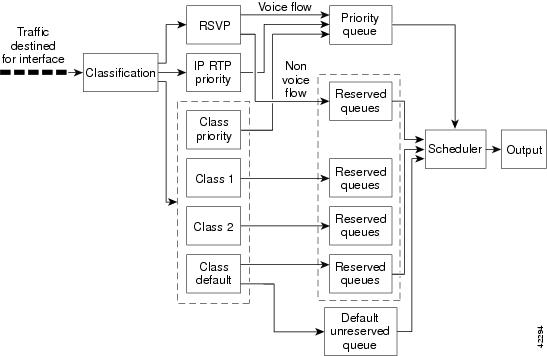
RSVP is the only protocol that provides admission control based on the availability of network resources such as bandwidth. LLQ provides a means to forward voice traffic with strict priority ahead of other data traffic. When combined, RSVP support for LLQ provides admission control and forwards voice flows with the lowest possible latency and jitter.
High priority nonvoice traffic from mission-critical applications can continue to be sent without being adversely affected by voice traffic.
Nonconformant traffic receives best-effort treatment, thereby avoiding any degradation that might otherwise occur for all traffic.
The RSVP Support for LLQ feature supports the following RFCs:
- RFC 2205, Resource Reservation Protoco l
- RFC 2210, RSVP with IETF Integrated Services
- RFC 2211, Controlled-Load Network Element Service
- RFC 2212, Specification of Guaranteed Quality of Service
- RFC 2215, General Characterization Parameters for Integrated Service Network Elements
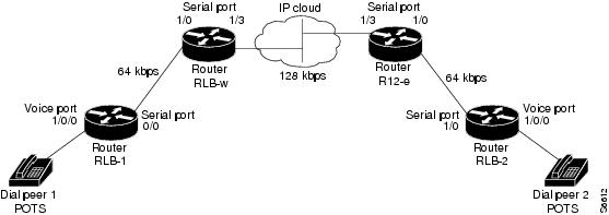
The figure below shows a sample network topology with LLQ running on each interface. This configuration guarantees QoS for voice traffic.
 Note | If the source is incapable of supporting RSVP, then the router can proxy on behalf of the source. |
For information on how to configure the RSVP Support for LLQ feature, see the "Configuring RSVP Support for LLQ" module.
RSVP Support for Frame Relay
Network administrators use queueing to manage congestion on a router interface or a virtual circuit (VC). In a Frame Relay environment, the congestion point might not be the interface itself, but the VC because of the committed information rate (CIR). For real-time traffic (voice flows) to be sent in a timely manner, the data rate must not exceed the CIR or packets might be dropped, thereby affecting voice quality. Frame Relay Traffic Shaping (FRTS) is configured on the interfaces to control the outbound traffic rate by preventing the router from exceeding the CIR. This type of configuration means that fancy queueing such as class-based WFQ (CBWFQ), LLQ, or WFQ, can run on the VC to provide the QoS guarantees for the traffic.
Previously, RSVP reservations were not constrained by the CIR of the outbound VC of the flow. As a result, oversubscription could occur when the sum of the RSVP traffic and other traffic exceeded the CIR.
The RSVP Support for Frame Relay feature allows RSVP to function with per-VC ( data-link connection identifier ( DLCI) queueing for voice-like flows. Traffic shaping must be enabled in a Frame Relay environment for accurate admission control of resources (bandwidth and queues) at the congestion point, that is, the VC itself. Specifically, RSVP can function with VCs defined at the interface and subinterface levels. There is no limit to the number of VCs that can be configured per interface or subinterface.
- RSVP Bandwidth Allocation and Modular QoS Command Line Interface (CLI)
- Benefits
- Restrictions
- Prerequisites
RSVP Bandwidth Allocation and Modular QoS Command Line Interface (CLI)
RSVP can use an interface (or a PVC) queueing algorithm, such as WFQ, to ensure QoS for its data flows.
Admission Control
When WFQ is running, RSVP can co-exist with other QoS features on an interface (or PVC) that also reserve bandwidth and enforce QoS. When you configure multiple bandwidth-reserving features (such as RSVP, LLQ, CB-WFQ, and ip rtp priority), portions of the interface's (or PVC's) available bandwidth may be assigned to each of these features for use with flows that they classify.
An internal interface-based (or PVC-based) bandwidth manager prevents the amount of traffic reserved by these features from oversubscribing the interface (or PVC). You can view this pool of available bandwidth using the show queue command.
When you configure features such as LLQ and CB-WFQ, any classes that are assigned a bandwidth reserve their bandwidth at the time of configuration, and deduct this bandwidth from the bandwidth manager. If the configured bandwidth exceeds the interface's capacity, the configuration is rejected.
When RSVP is configured, no bandwidth is reserved. (The amount of bandwidth specified in the ip rsvp bandwidth command acts as a strict upper limit, and does not guarantee admission of any flows.) Only when an RSVP reservation arrives does RSVP attempt to reserve bandwidth out of the remaining pool of available bandwidth (that is, the bandwidth that has not been dedicated to traffic handled by other features.)
Data Packet Classification
By default, RSVP performs an efficient flow-based, datapacket classification to ensure QoS for its reserved traffic. This classification runs prior to queueing consideration by ip rtp priority or CB-WFQ. Thus, the use of a CB-WFQ class or ip rtp priority command is notrequired in order for RSVP data flows to be granted QoS. Any ip rtp priority or CB-WFQ configuration will not match RSVP flows, but they will reserve additional bandwidth for any non-RSVP flows that may match their classifiers.
Benefits
The benefits of this feature include the following:
- RSVP now provides admission control based on the VC minimum acceptable outgoing (minCIR) value, if defined, instead of the amount of bandwidth available on the interface.
- RSVP provides QoS guarantees for high priority traffic by reserving resources at the point of congestion, that is, the Frame Relay VC instead of the interface.
- RSVP provides support for point-to-point and multipoint interface configurations, thus enabling deployment of services such as VoIP in Frame Relay environments with QoS guarantees.
- RSVP, CBWFQ, and the ip rtp priority command do not oversubscribe the amount of bandwidth available on the interface or the VC even when they are running simultaneously. Prior to admitting a reservation, these features (and the ip rtp prioritycommand) consult with an internal bandwidth manager to avoid oversubscription.
- IP QoS features can now be integrated seamlessly from IP into Frame Relay environments with RSVP providing admission control on a per-VC (DLCI) basis.
The RSVP Support for Frame Relay feature supports the following MIB and RFCs:
- RFC 2206, RSVP Management Information Base using SMIv2
- RFC 220, Resource Reservation Protocol
- RFC 2210, RSVP with IETF Integrated Services
- RFC 221, Controlled-Load Network Element Service
- RFC 2212, Specification of Guaranteed Quality of Service
- RFC 2215, General Characterization Parameters for Integrated Service Network Elements
For information on how to configure RVSP Support for Frame Relay, see the "Configuring RSVP Support for Frame Relay" module.
Restrictions
The following restrictions apply to the RSVP Support for Frame Relay feature:
- Interface-level Generic Traffic Shaping (GTS) is not supported.
- VC-level queueing and interface-level queueing on the same interface are not supported.
- Nonvoice RSVP flows are not supported.
- Multicast flows are not supported.
RSVP-ATM QoS Interworking
The RSVP-ATM QoS Interworking feature provides support for Controlled Load Service using RSVP over an ATM core network. This feature requires the ability to signal for establishment of switched virtual circuits (SVCs) across the ATM cloud in response to RSVP reservation request messages. To meet this requirement, RSVP over ATM supports mapping of RSVP sessions to ATM SVCs.
The RSVP-ATM QoS Interworking feature allows you to perform the following tasks:
- Configure an interface or subinterface to dynamically create SVCs in response to RSVP reservation request messages. To ensure defined QoS, these SVCs are established having QoS profiles consistent with the mapped RSVP flow specifications (flowspecs).
- Attach Distributed Weighted Random Early Detection (DWRED) group definitions to the Enhanced ATM port adapter (PA-A3) interface to support per-VC DWRED drop policy. Use of per-VC DWRED ensures that if packets must be dropped, then best-effort packets are dropped first and not those that conform to the appropriate QoS determined by the token bucket of RSVP.
- Configure the IP Precedence and ToS values to be used for packets that conform to or exceed QoS profiles. As part of its input processing, RSVP uses the values that you specify to set the ToS and IP Precedence bits on incoming packets. If per-VC DWRED is configured, it then uses the ToS and IP Precedence bit settings on the output interface of the same router in determining which packets to drop. Also, interfaces on downstream routers use these settings in processing packets.
This feature is supported on Cisco 7500 series routers with a VIP2-50 and Enhanced ATM port adapter (PA-A3). The hardware provides the traffic shaping required by the feature and satisfies the OC-3 rate performance requirement.
How It Works
Traditionally, RSVP has been coupled with WFQ. WFQ provides bandwidth guarantees to RSVP and gives RSVP visibility to all packets visible to it. This visibility allows RSVP to identify and mark packets pertinent to it.
The RSVP-ATM QoS Interworking feature allows you to decouple RSVP from WFQ, and instead associate it with ATM SVCs to handle reservation request messages (and provide bandwidth guarantees) and NetFlow to make packets visible to RSVP.
To configure an interface or subinterface to use the RSVP-ATM QoS Interworking feature, use the ip rsvp svc-required command. Then, whenever a new RSVP reservation is requested, the router software establishes a new ATM SVC to service the reservation.
To ensure correspondence between RSVP and ATM SVC values, the software algorithmically maps the rate and burst size parameters in the RSVP flowspec to the ATM sustained cell rate (SCR) and maximum burst size (MBS). For the peak cell rate (PCR), it uses the value you configure or it defaults to the line rate. RSVP-ATM QoS Interworking requires an Enhanced ATM port adapter (PA-A3) with OC-3 speed.
When a packet belonging to a reserved flow arrives on the interface or subinterface, the RSVP-ATM QoS Interworking software uses a token bucket to manage bandwidth guarantees. It measures actual traffic rates against the reservation flowspec to determine if the packet conforms to or exceeds the flowspec. Using values you configure for conformant or exceeding traffic, it sets the IP Precedence and ToS bits in the ToS byte of the header of the packet and delivers the packet to the appropriate virtual circuit (VC) for transmission. For the RSVP-ATM QoS Interworking feature, packets are shaped before they are sent on the ATM SVC. Shaping creates back pressure to the Versatile Interface Processor (VIP) when the offered load exceeds the rate.
The RSVP-ATM QoS Interworking software uses per-SVC DWRED to drop packets when shaping causes a queue to build up on the VIP. Use of per-SVC DWRED allows RSVP to deliver Controlled Load Service class, which requires that reserved packets experience performance equivalent to that of an unloaded network (which is one with very low loss and moderate delay). For a more detailed account of how the RSVP-ATM QoS Interworking feature works, see the following example scenario.
An Example Scenario
To understand the behavior of the RSVP-ATM QoS Interworking feature, consider the following example, which uses a Cisco 7500 router with VIP ingress and egress interfaces and RSVP ingress functionality implemented on the Route Switch Processor (RSP). The figure below illustrates this example; it shows a pair of routers that communicate over the ATM cloud. In this example, a single PVC is used for RSVP request messages and an ATM SVC is established to handle each new reservation request message.

Host X, which is upstream from Router A, is directly connected to Router A using FDDI. Host Y, which is downstream from Router B, is directly connected to Router B using FDDI. (In an alternative configuration, these host-router connections could use ATM VCs.)
For the RSVP-ATM QoS Interworking feature, reservations are needed primarily between routers across the ATM backbone network. To limit the number of locations where reservations are made, you can enable RSVP selectively only at subinterfaces corresponding to router-to-router connections across the ATM backbone network. Preventing reservations from being made between the host and the router both limits VC usage and reduces load on the router.
RSVP RESV messages flow from receiving host to sending host. In this example, Host Y is the sending host and Host X is the receiving host. (Host Y sends a RESV message to Host X.) Router B, which is at the edge of the ATM cloud, receives the RESV message and forwards it upstream to Router A across the PVC used for control messages. The example configuration shown in the figure above uses one PVC; as shown, it carries the RSVP request.
The ingress interface on Router A is configured for RSVP-ATM, which enables it to establish for each request an SVC to service any new RSVP RESV reservations made on the interface. When it receives a reservation request, the interface on Router A creates a new nonreal-time variable bit rate (nRTVBR) SVC with the appropriate QoS characteristics. The QoS characteristics used to establish the SVC result from algorithmic mapping of the flowspec in the RSVP RESV message to the appropriate set of ATM signalling parameters.
In this example, Controlled Load Service is used as the QoS class. The ATM PCR parameter is set to the line rate. If the ip rsvp atm-peak-rate-limit command is used on the interface to configure a rate limiter, the PCR is set to the peak rate limiter. The ATM SCR parameter is set to the RSVP flowspec rate and the ATM MBS is set to the RSVP flowspec burst size. Packets are shaped before they are sent on the ATM SVC. Shaping creates back pressure to the VIP when the offered load exceeds the rate.
When a new SVC is set up to handle a reservation request, another state is also set up including a classifier state that uses a source and destination addresses and port numbers of the packet to determine which, if any, reservation the packet belongs to. Also, a token bucket is set up to ensure that if a source sends more data than the data rate and MBS parameters of its flowspec specify, the excess traffic does not interfere with other reservations.
The following section describes more specifically, how data traverses the path.
When a data packet destined for Router B arrives at Router A, before they traverse the ATM cloud, the source and destination addresses and port numbers of the packet are checked against the RSVP filter specification (filterspec) to determine if the packet matches a reservation.
If the packet does not match a reservation, it is sent out the best-effort PVC to Router B. If a packet matches a reservation, it is further processed by RSVP. The packet is checked against the token bucket of the reservation to determine whether it conforms to or exceeds the token bucket parameters. (All packets matching a reservation are sent out on the SVC of the reservation to prevent misordering of packets.)
To introduce differentiation between flowspec-conformant and flowspec-exceeding packets, you can specify values for RSVP-ATM to use in setting the IP Precedence and ToS bits of the packets. To specify these values, you use the ip rsvp precedence and ip rsvp tos commands. When you set different precedence values for conformant and exceeding packets and use a preferential drop policy such as DWRED, RSVP-ATM ensures that flowspec-exceeding packets are dropped prior to flowspec-conformant packets when the VC is congested.
For information on how to configure the RSVP-ATM QoS Interworking feature, see the "Configuring RSVP-ATM QoS Interworking" module.
COPS for RSVP
Common Open Policy Service (COPS) is a protocol for communicating network traffic policy information to network devices. RSVP is a means for reserving network resources--primarily bandwidth--to guarantee that applications sending end-to-end across the Internet will perform at the desired speed and quality.
Combined, COPS with RSVP gives network managers centralized monitoring and control of RSVP, including the following abilities:
- Ensure adequate bandwidth and jitter and delay bounds for time-sensitive traffic such as voice transmission
- Ensure adequate bandwidth for multimedia applications such as video conferencing and distance learning
- Prevent bandwidth-hungry applications from delaying top priority flows or harming the performance of other applications customarily run over the same network
In so doing, COPS for RSVP supports the following crucial RSVP features:
- Admission control. The RSVP reservation is accepted or rejected based on end-to-end available network resources.
- Bandwidth guarantee. The RSVP reservation, if accepted, will guarantee that those reserved resources will continue to be available while the reservation is in place.
- Media-independent reservation. An end-to-end RSVP reservation can span arbitrary lower layer media types.
- Data classification. While a reservation is in place, data packets belonging to that RSVP flow are separated from other packets and forwarded as part of the reserved flow.
- Data policing. Data packets belonging to an RSVP flow that exceed the reserved bandwidth size are marked with a lower packet precedence.
Note | The Cisco IOS 12.1(2)T release of COPS for RSVP does not support RSVP+. |
COPS for RSVP functions on the following interfaces:
- Ethernet
- Fast Ethernet
- High-Speed Serial Interface (HSSI): V.35, EIA/TIA-232
- T1
The COPS for RSVP feature supports the following RFCs:
- RFC 2749, COPS Usage for RSVP
- RFC 2205, Resource ReSerVation Protocol (RSVP)
- RFC 2748, The COPS (Common Open Policy Service) Protocol
How It Works
This section provides a high-level overview of how the COPS for RSVP feature works on your network, and provides the general steps for configuring the COPS for RSVP feature.
The figure below is a sample arrangement of COPS with RSVP.
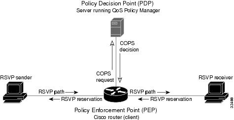
To configure a router to process all RSVP messages coming to it according to policies stored on a particular policy server (called the Policy Decision Point, or PDP), perform the following steps:
- At the PDP server enter the policies using the Cisco COPS QoS Policy Manager or a compatible policy manager application.
- Configure the router (through its command-line interface) to request decisions from the server regarding RSVP messages.
After that configuration, network flows are processed by the router designated as the Policy Enforcement Point (PEP), as follows:
- When an RSVP signalling message arrives at the router, the router asks the PDP server how to process the message, either to accept, reject, forward, or install the message.
- The PDP server sends its decision to the router, which then processes the message as instructed.
- Alternatively, you may configure the router to make those decisions itself ("locally") without it needing to consult first with the PDP server. (The local feature is not supported in this release but will be in a future release.)
A Detailed Look at COPS for RSVP Functioning
The figure below traces options available in policy management of RSVP message flows. For each option, an example of the router configuration command used for setting that option is given in brackets and boldface type.
The shaded area covers local policy operations; the remainder of the figure illustrates remote policy operation. (Configuring local policy will be available in a future release.)
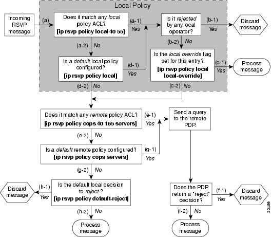
- The router receives a PATH or RESV message and first tries to adjudicate it locally (that is, without referring to the policy server). If the router has been configured to adjudicate specific access control lists (ACLs) locally and the message matches one of those lists (a-1), the policy module of the router applies the operators with which it had been configured. Otherwise, policy processing continues (a-2).
- For each message rejected by the operators, the router sends an error message to the sender and removes the PATH or RESV message from the database (b-1). If the message is not rejected, policy processing continues (b-2).
- If the local override flag is set for this entry, the message is immediately accepted with the specified policy operators (c-1). Otherwise, policy processing continues (c-2).
- If the message does not match any ACL configured for local policy (a-2), the router applies the default local policy (d-1). However, if no default local policy has been configured, the message is directed toward remote policy processing (d-2).
- If the router has been configured with specific ACLs against specific policy servers (PDPs), and the message matches one of these ACLs, the router sends that message to the specific PDP for adjudication (e-1). Otherwise, policy processing continues (e-2).
- If the PDP specifies a "reject" decision (f-1), the message is discarded and an error message is sent back to the sender, indicating this condition. If the PDP specifies an "accept" decision (f-2), the message is accepted and processed using normal RSVP processing rules.
- If the message does not match any ACL configured for specific PDPs (e-2), the router applies the default PDP configuration. If a default COPS configuration has been entered, policy processing continues (g-1). Otherwise, the message is considered to be unmatched (g-2).
If the default policy decision for unmatched messages is to reject (h-1), the message is immediately discarded and an ERROR message is sent to the sender indicating this condition. Otherwise, the message is accepted and processed using normal RSVP processing rules (h-2).
Here are additional details about PDP-PEP communication and processing:
- Policy request timer. Whenever a request for adjudication (of any sort) is sent to a PDP, a 30-second timer associated with the PATH or RESV message is started. If the timer runs out before the PDP replies to the request, the PDP is assumed to be down and the request is given to the default policy (step g-2 in the figure above).
- PDP tracking of PEP reservations. When the PDP specifies that a reservation can be installed, this reservation must then be installed on the router. Once bandwidth capacity has been allocated and the reservation installed, the policy module of the PEP sends a COMMIT message to the PDP. But if the reservation could not be installed because of insufficient resources, the reservation is folded back to the noninstalled state and a NO-COMMIT message is sent to the PDP. If the reservation was also new (no previous state), then a DELETE REQUEST message instead is sent to the PDP. In these ways, the PDP can keep track of reservations on the PEP.
- Resynchronization. If the PDP sends a SYNCHRONIZE-REQUEST message to the PEP, the policy module of the PEP scans its database for all paths and reservations that were previously adjudicated by this PDP, and resends requests for them. The previously adjudicated policy information is retained until a new decision is received. When all the PATH or RESV states have been reported to the PDP, a SYNCHRONIZE-COMPLETE message is sent by the policy module to the PDP. The PEP also sends queries concerning all flows that were locally adjudicated while the PDP was down.
- Readjudication:
- So long as flows governed by the RSVP session continue to pass through the PEP router, the PDP can unilaterally decide to readjudicate any of the COPS decisions of that session. For example, the PDP might decide that a particular flow that was earlier granted acceptance now needs to be rejected (due perhaps to a sudden preemption or timeout). In such cases, the PDP sends a new decision message to the PEP, which then adjusts its behavior accordingly.
- If the PEP router receives a RESV message in which an object has changed, the policy decision needs to be readjudicated. For example, if the sender wants to increase or decrease the bandwidth reservation, a new policy decision must be made. In such cases, the policy flags previously applied to this session are retained, and the session is readjudicated.
- Tear-downs. The policy module of the PEP is responsible for notifying the PDP whenever a reservation or path that was previously established through policy is torn down for any reason. The PEP notifies the PDP by sending the PDP a DELETE REQUEST message.
- Connection management:
- If the connection to the PDP is closed (either because the PDP closed the connection, a TCP/IP error occurred, or the keepalives failed), the PEP issues a CLIENT-CLOSE message and then attempts to reconnect to the same PDP. If the PEP receives a CLIENT-CLOSE message containing a PDP redirect address, the PEP attempts to connect to the redirected PDP.
- If either attempt fails, the PEP attempts to connect to the PDPs previously specified in the configuration ip rsvp policy cops servers command, obeying the sequence of servers given in that command, always starting with the first server in that list.
- If the PEP reaches the end of the list of servers without connecting, it waits a certain time (called the "reconnect delay") before trying again to connect to the first server in the list. This reconnect delay is initially 30 seconds, and doubles each time the PEP reaches the end of the list without having connected, until the reconnect delay becomes its maximum of 30 minutes. As soon as a connection is made, the delay is reset to 30 seconds.
- Replacement objects--The matrix in the table below identifies objects that the PDP can replace within RSVP messages passing through the PEP. An x in the column indicates that the PDP can replace the particular object within RSVP messages.
| Table 1 | Matrix for Objects the PDP Can Replace Within RSVP Messages |
If an RSVP message whose object was replaced is later refreshed from upstream, the PEP keeps track of both the old and new versions of the object, and does not wrongly interpret the refresh as a change in the PATH or RESV state.
For information on how to configure COPS for RSVP, see the chapter "Configuring COPS for RSVP" in this book.
Subnetwork Bandwidth Manager
RSVP and its service class definitions are largely independent of the underlying network technologies. This independence requires that a user define the mapping of RSVP onto subnetwork technologies.
The Subnetwork Bandwidth Manager (SBM) feature answers this requirement for RSVP in relation to IEEE 802-based networks. SBM specifies a signalling method and protocol for LAN-based admission control for RSVP flows. SBM allows RSVP-enabled routers and Layer 2 and Layer 3 devices to support reservation of LAN resources for RSVP-enabled data flows. The SBM signalling method is similar to that of RSVP itself. SBM protocol entities have the following features:
- Reside in Layer 2 or Layer 3 devices.
- Can manage resources on a segment. A segment is a Layer 2 physical segment shared by one or more senders, such as a shared Ethernet or Token Ring wire.
- Can become candidates in a dynamic election process that designates one SBM as the segment manager. The elected candidate is called the Designated Subnetwork Bandwidth Manager (DSBM). The elected DSBM is responsible for exercising admission control over requests for resource reservations on a managed segment.
A managed segment includes those interconnected parts of a shared LAN that are not separated by DSBMs. The presence of a DSBM makes the segment a managed one. One or more SBMs may exist on a managed segment, but there can be only one DSBM on each managed segment.
You can configure an interface on routers connected to the segment to participate in the DSBM election process. The contender configured with the highest priority becomes the DSBM for the managed segment.
If you do not configure a router as a DSBM candidate and RSVP is enabled, then the system interacts with the DSBM if a DSBM is present on the segment. In fact, if a DSBM, identifying itself as such, exists on the segment, the segment is considered a managed segment and all RSVP message forwarding will be based on the SBM message forwarding rules. This behavior exists to allow cases in which you might not want an RSVP-enabled interface on a router connected to a managed segment interface to become a DSBM, but you want it to interact with the DSBM if one is present managing the segment.
Note | SBM is not supported currently on Token Ring LANs. |
The figure below shows a managed segment in a Layer 2 domain that interconnects a set of hosts and routers.
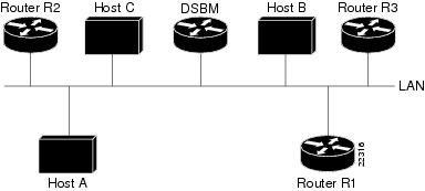
When a DSBM client sends or forwards an RSVP PATH message over an interface attached to a managed segment, it sends the PATH message to the DSBM of the segment instead of to the RSVP session destination address, as is done in conventional RSVP processing. As part of its message processing procedure, the DSBM builds and maintains a PATH state for the session and notes the previous Layer 2 or Layer 3 hop from which it received the PATH message. After processing the PATH message, the DSBM forwards it toward its destination address.
The DSBM receives the RSVP RESV message and processes it in a manner similar to how RSVP itself handles reservation request processing, basing the outcome on available bandwidth. The procedure is as follows:
- If it cannot grant the request because of lack of resources, the DSBM returns a RESVERROR message to the requester.
- If sufficient resources are available and the DSBM can grant the reservation request, it forwards the RESV message toward the previous hops using the local PATH state for the session.
For information on how to configure SBM, see the "Configuring Subnetwork Bandwidth Manager" module.
Cisco and the Cisco logo are trademarks or registered trademarks of Cisco and/or its affiliates in the U.S. and other countries. To view a list of Cisco trademarks, go to this URL: www.cisco.com/go/trademarks. Third-party trademarks mentioned are the property of their respective owners. The use of the word partner does not imply a partnership relationship between Cisco and any other company. (1110R)
Any Internet Protocol (IP) addresses and phone numbers used in this document are not intended to be actual addresses and phone numbers. Any examples, command display output, network topology diagrams, and other figures included in the document are shown for illustrative purposes only. Any use of actual IP addresses or phone numbers in illustrative content is unintentional and coincidental.