
 Feedback
Contents
- RSVP Aggregation
- Finding Feature Information
- Prerequisites for RSVP Aggregation
- Restrictions for RSVP Aggregation
- Information About RSVP Aggregation
- Feature Overview of RSVP Aggregation
- High Level Overview
- How Aggregation Functions
- Aggregate RSVP DiffServ Integration Topology
- Integration with RSVP Features
- Benefits of RSVP Aggregation
- How to Configure RSVP Aggregation
- Configuring RSVP Scalability Enhancements
- Enabling RSVP on an Interface
- Setting the Resource Provider
- Disabling Data Packet Classification
- Configuring Class and Policy Maps
- Attaching a Policy Map to an Interface
- Configuring Interfaces with Aggregation Role
- Configuring Aggregation Mapping on a Deaggregator
- Configuring Aggregate Reservation Attributes on a Deaggregator
- Configuring an RSVP Aggregation Router ID
- Enabling RSVP Aggregation
- Configuring RSVP Local Policy
- Verifying the RSVP Aggregation Configuration
- Configuration Examples for RSVP Aggregation
- Examples Configuring RSVP Aggregation
- Example Verifying the RSVP Aggregation Configuration
- Additional References
- Feature Information for RSVP Aggregation
- Glossary
RSVP Aggregation
The RSVP Aggregation feature allows the Resource Reservation Protocol (RSVP) state to be reduced within an RSVP/DiffServ network by aggregating many smaller reservations into a single, larger reservation at the edge.
Finding Feature Information
Your software release may not support all the features documented in this module. For the latest caveats and feature information, see Bug Search Tool and the release notes for your platform and software release. To find information about the features documented in this module, and to see a list of the releases in which each feature is supported, see the feature information table at the end of this module.
Use Cisco Feature Navigator to find information about platform support and Cisco software image support. To access Cisco Feature Navigator, go to www.cisco.com/go/cfn. An account on Cisco.com is not required.
Prerequisites for RSVP Aggregation
You must configure at least two aggregating nodes (provider edge [PE] devices), one interior node (provider [P] device) and two end user nodes (customer edge [CE] devices) within your network.
You must configure your network to support the following Cisco IOS features:
- RSVP
- Class Based Weighted Fair Queuing (CBWFQ)
- RSVP Scalability Enhancements
 Note | You configure these features because Cisco IOS Release 12.2(33)SRC supports control plane aggregation only. Dataplane aggregation must be achieved by using the RSVP Scalability Enhancements. |
Restrictions for RSVP Aggregation
Functionality Restrictions
The following functionality is not supported:
- Multilevel aggregation
- Multiple, adjacent aggregation regions
- Dynamic resizing of aggregate reservations
- Policing of end-to-end (E2E) reservations by the aggregator
- Policing of aggregate reservations by interior routers
- Differentiated Services Code Point (DSCP) marking by the aggregator
- Equal Cost Multiple Paths (ECMP) load-balancing within the aggregation region
- RSVP Fast Local Repair in case of a routing change resulting in a different aggregator or deaggregator, admission control is performed on E2E PATH refresh
- Multicast RSVP reservations
- RSVP policy servers including Common Open Policy Server (COPS)
- Dataplane aggregation
The following functionality is supported:
- Multiple, non-adjacent aggregation regions
- Control plane aggregation
Note | RSVP/DiffServ using CBWFQ provides the dataplane aggregation. |
Configuration Restrictions
- Sources should not send marked packets without an installed reservation.
- Sources should not send marked packets that exceed the reserved bandwidth.
- Sources should not send marked packets to a destination other than the reserved path.
- All RSVP capable routers within an aggregation region regardless of role must support the aggregation feature to recognize the RFC 3175 RSVP message formats properly.
- E2E reservations must be present to establish dynamic aggregates; aggregates cannot be established manually.
- Aggregates are established at a fixed bandwidth regardless of the number of current E2E reservations being aggregated.
- Aggregators and deaggregators must be paired to avoid blackholing of E2E reservations because of dynamic aggregate establishment.
Information About RSVP Aggregation
Feature Overview of RSVP Aggregation
High Level Overview
The establishment of a single RSVP reservation requires a large amount of resources including memory allocated for the associated data structures, CPU for handling signaling messages, I/O operations for datapath programming, interprocess communication, and signaling message transmission.
When a large number of small reservations are established, the resources required for setting and maintaining these reservations may exceed a node's capacity to the point where the node's performance is significantly degraded or it becomes unusable. The RSVP Aggregation feature addresses this scalability issue by introducing flow aggregation.
Flow aggregation is a mechanism wherein RSVP state can be reduced within a core router by aggregating many smaller reservations into a single, larger reservation at the network edge. This preserves the ability to perform connection admission control on core router links within the RSVP/DiffServ network while reducing signaling resource overhead.
How Aggregation Functions
Common segments of multiple end-to-end (E2E) reservations are aggregated over an aggregation region into a larger reservation that is called an aggregate reservation. An aggregation region is a connected set of nodes that are capable of performing RSVP aggregation as shown in the figure below.
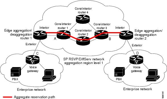
There are three types of nodes within an aggregation region:
- Aggregator--Aggregates multiple E2E reservations.
- Deaggregator--Deaggregates E2E reservations; provides mapping of E2E reservations onto aggregates.
- Interior--Neither aggregates or deaggregates, but is an RSVP core router that understands RFC 3175 formatted RSVP messages. Core/interior routers 1 through 4 are examples shown in the figure above.
There are two types of interfaces on the aggregator/deaggregator nodes:
- Exterior interface--The interface is not part of the aggregate region.
- Interior interface--The interface is part of the aggregate region.
Any router that is part of the aggregate region must have at least one interior interface and may have one or more exterior interfaces. Depending on the types of interfaces spanned by an IPv4 flow, a node can be an aggregator, a deaggregator, or an interior router with respect to that flow.
Aggregate RSVP DiffServ Integration Topology
RSVP aggregation further enhances RSVP scalability within an RSVP/DiffServ network as shown in the figure above by allowing the establishment of aggregate reservations across an aggregation region. This allows for aggregated connection admission control on core/interior router interfaces. Running RSVP on the core/interior routers allows for more predictable bandwidth use during normal and failure scenarios.
The voice gateways are running classic RSVP, which means RSVP is keeping a state per flow and also classifying, marking, and scheduling packets on a per-flow basis. The edge/aggregation routers are running RSVP with scalability enhancements for admission control on the exterior interfaces connected to the voice gateways and running RSVP aggregation on the interfaces connected to core/interior routers 1 and 3. The core/interior routers in the RSVP/DiffServ network are running RSVP for the establishment of the aggregate reservations. The edge and core/interior routers inside the RSVP/DiffServ network also implement a specific per hop behavior (PHB) for a collection of flows that have the same DSCP.
The voice gateways identify voice data packets and set the appropriate DSCP in their IP headers so that the packets are classified into the priority class in the edge/aggregation routers and in core/interior routers 1, 2, 3 or 1, 4, 3.
The interior interfaces on the edge/aggregation/deaggregation routers (labeled A and B) connected to core/interior routers 1 and 3 are running RSVP aggregation. They are performing admission control only per flow against the RSVP bandwidth of the aggregate reservation for the corresponding DSCP.
Admission control is performed at the deaggregator because it is the first edge node to receive the returning E2E RSVP RESV message. CBWFQ is performing the classification, policing, and scheduling functions on all nodes within the RSVP/DiffServ network including the edge routers.
Aggregate reservations are dynamically established over an aggregation region when an E2E reservation enters an aggregation region by crossing from an exterior to an interior interface; for example, when voice gateway C initiates an E2E reservation to voice gateway D. The aggregation is accomplished by "hiding" the E2E RSVP messages from the RSVP nodes inside the aggregation region. This is achieved with a new IP protocol, RSVP-E2E-IGNORE, that replaces the standard RSVP protocol in E2E PATH, PATHTEAR, and RESVCONF messages. This protocol change to RSVP-E2E-IGNORE is performed by the aggregator when the message enters the aggregation region and later restored back to RSVP by the deaggregator when the message exits the aggregation region. Thus, the aggregator and deaggregator pairs for a given flow are dynamically discovered during the E2E PATH establishment.
The deaggregator router 2 is responsible for mapping the E2E PATH onto an aggregate reservation per the configured policy. If an aggregate reservation with the corresponding aggregator router 1 and a DSCP is established, the E2E PATH is forwarded. Otherwise a new aggregate at the requisite DSCP is established, and then the E2E PATH is forwarded. The establishment of this new aggregate is for the fixed bandwidth parameters configured at the deaggregator router 2. Aggregate PATH messages are sent from the aggregator to the deaggregator using RSVP's normal IP protocol. Aggregate RESV messages are sent back from the deaggregator to the aggregator, thus establishing an aggregate reservation on behalf of the set of E2E flows that use this aggregator and deaggregator. All RSVP capable interior nodes process the aggregate reservation request following normal RSVP processing including any configured local policy.
The RSVP-E2E-IGNORE messages are ignored by the core/interior routers, no E2E reservation states are created, and the message is forwarded as IP. As a consequence, the previous hop/next hop (PHOP/ NHOP) for each RSVP-E2E-IGNORE message received at the deaggregator or aggregator is the aggregator or deaggregator node. Therefore, all messages destined to the next or previous hop (RSVP error messages, for example) do not require the protocol to be changed when they traverse the aggregation region.
By setting up a small number of aggregate reservations on behalf of a large number of E2E flows, the number of states stored at core/interior routers and the amount of signal processing within the aggregation region is reduced.
In addition, by using differentiated services mechanisms for classification and scheduling of traffic supported by aggregate reservations rather than performing per aggregate reservation classification and scheduling, the amount of classification and scheduling state in the aggregation region is further reduced. This reduction is independent of the number of E2E reservations and the number of aggregate reservations in the aggregation region. One or more RSVP/DiffServ DSCPs are used to identify the traffic covered by aggregate reservations, and one or more RSVP/DiffServ per hop behaviors (PHBs) are used to offer the required forwarding treatment to this traffic. There may be more than one aggregate reservation between the same pair of routers, each representing different classes of traffic and each using a different DSCP and a different PHB.
Benefits of RSVP Aggregation
Enhanced Scalability
Aggregating a large number of small reservations into one reservation requires fewer resources for signaling, setting, and maintaining the reservation thereby increasing scalability.
Enhanced Bandwidth Usage within RSVP/DiffServ Core Network
Aggregate reservations across an RSVP/DiffServ network allow for more predictable bandwidth use of core links across RSVP/DiffServ PHBs. Aggregate reservations can use RSVP fast local repair and local policy preemption features for determining bandwidth use during failure scenarios.
How to Configure RSVP Aggregation
- Configuring RSVP Scalability Enhancements
- Configuring Interfaces with Aggregation Role
- Configuring Aggregation Mapping on a Deaggregator
- Configuring Aggregate Reservation Attributes on a Deaggregator
- Configuring an RSVP Aggregation Router ID
- Enabling RSVP Aggregation
- Configuring RSVP Local Policy
- Verifying the RSVP Aggregation Configuration
Configuring RSVP Scalability Enhancements
Note | All interfaces on nodes running Cisco IOS Release 12.2(33)SRC software must be configured with RSVP Scalability Enhancements. |
Perform these tasks on all nodes within the aggregation region including aggregators, deaggregators, and interior nodes.
This section includes the following procedures:
- Enabling RSVP on an Interface
- Setting the Resource Provider
- Disabling Data Packet Classification
- Configuring Class and Policy Maps
- Attaching a Policy Map to an Interface
Enabling RSVP on an Interface
DETAILED STEPS
Setting the Resource Provider
DETAILED STEPS
| Command or Action | Purpose | |||
|---|---|---|---|---|
Step 1 |
enable
Example: Router> enable |
Enables privileged EXEC mode. | ||
Step 2 |
configure
terminal
Example: Router# configure terminal |
Enters global configuration mode. | ||
Step 3 | interface
type number Example: Router(config)# interface Ethernet0/0 |
Configures the interface type and enters interface configuration mode. | ||
Step 4 | ip rsvp resource-provider [none | wfq-interface | wfq-pvc]
Example: Router(config-if)# ip rsvp resource-provider none |
Sets the resource provider.
| ||
Step 5 |
end
Example: Router(config-if)# end |
(Optional) Returns to privileged EXEC mode. |
Disabling Data Packet Classification
Note | Disabling data packet classification instructs RSVP not to process every packet, but to perform admission control only. |
DETAILED STEPS
| Command or Action | Purpose | |
|---|---|---|
Step 1 |
enable
Example: Router> enable |
Enables privileged EXEC mode. |
Step 2 |
configure
terminal
Example: Router# configure terminal |
Enters global configuration mode. |
Step 3 | interface
type number Example: Router(config)# interface Ethernet0/0 |
Configures the interface type and enters interface configuration mode. |
Step 4 | ip rsvp data-packet classification none
Example: Router(config-if)# ip rsvp data-packet classification none |
Disables data packet classification. |
Step 5 |
end
Example: Router(config-if)# end |
(Optional) Returns to privileged EXEC mode. |
Configuring Class and Policy Maps
DETAILED STEPS
| Command or Action | Purpose | |||||||
|---|---|---|---|---|---|---|---|---|
Step 1 |
enable
Example: Router> enable |
Enables privileged EXEC mode.
| ||||||
Step 2 |
configure
terminal
Example: Router# configure terminal |
Enters global configuration mode. | ||||||
Step 3 |
class-map [type {stack | access-control | port-filter | queue-threshold}] [match-all | match-any] class-map-name Example: Router(config)# class-map match-all voice |
Creates a class map to be used for matching packets to a specified class and enters class-map configuration mode.
| ||||||
Step 4 |
match
access-group
{access-group | name access-group-name} Example: Router(config-cmap)# match access-group 100 |
Specifies the numbered access list against whose contents packets are checked to determine if they match the criteria specified in the class map.
| ||||||
Step 5 |
exit
Example: Router(config-cmap)# exit |
Exits to global configuration mode. | ||||||
Step 6 |
policy-map [type access-control] policy-map-name Example: Router(config)# policy-map wfq-voip |
Creates or modifies a policy map that can be attached to one or more interfaces to specify a service policy and enters policy-map configuration mode.
| ||||||
Step 7 |
class {class-name | class-default} Example: Router(config-pmap-c)# class voice |
Specifies the class so that you can configure or modify its policy. Enters policy-map class configuration mode.
| ||||||
Step 8 |
priority {bandwidth-kbps | percent percentage} [burst] Example: Router(config-pmap-c)# priority 24 |
(Optional) Prioritizes a class of traffic belonging to a policy map.
| ||||||
Step 9 |
end
Example: Router(config--pmap-c)# end |
(Optional) Returns to privileged EXEC mode. |
Attaching a Policy Map to an Interface
Note | If at the time you configure the RSVP scalability enhancements, there are existing reservations that use classic RSVP, no additional marking, classification, or scheduling is provided for these flows. You can also delete these reservations after you configure the RSVP scalability enhancements. |
DETAILED STEPS
| Command or Action | Purpose | |||
|---|---|---|---|---|
Step 1 |
enable
Example: Router> enable |
Enables privileged EXEC mode. | ||
Step 2 |
configure
terminal
Example: Router# configure terminal |
Enters global configuration mode. | ||
Step 3 | interface
type number Example: Router(config)# interface Ethernet0/0 |
Configures the interface type and enters interface configuration mode. | ||
Step 4 |
service-policy
[type access-control] {input
|
output} policy-map-name
Example: Router(config-if)# service-policy output POLICY-ATM |
Specifies the name of the policy map to be attached to the input or output direction of the interface.
| ||
Step 5 |
end
Example: Router(config-if)# end |
(Optional) Returns to privileged EXEC mode. |
Configuring Interfaces with Aggregation Role
Perform this task on aggregator and deaggregators to specify which interfaces are facing the aggregation region.
Note | You do not need to perform this task on interior routers; that is, nodes having interior interfaces only. |
DETAILED STEPS
| Command or Action | Purpose | |
|---|---|---|
Step 1 |
enable
Example: Router> enable |
Enables privileged EXEC mode.
|
Step 2 |
configure
terminal
Example: Router# configure terminal |
Enters global configuration mode. |
Step 3 |
interface type number Example: Router(config)# interface Ethernet0/0 |
Configures the interface type and enters interface configuration mode. |
Step 4 |
ip
rsvp
aggregation
role
interior
Example: Router(config-if)# ip rsvp aggregation role interior |
Enables RSVP aggregation on an aggregator or deaggregator's interface. |
Step 5 |
Repeat Step 4 as needed to configure additional aggregator and deaggregator interfaces. |
Configures additional aggregator and deaggregator interfaces. |
Step 6 |
end
Example: Router(config-if)# end |
(Optional) Returns to privileged EXEC mode. |
Configuring Aggregation Mapping on a Deaggregator
Note | Typically, an edge router acts as both an aggregator and deaggregator because of the unidirectional nature of RSVP reservations. Most applications require bidirectional reservations. Therefore, these parameters are used by a deaggregator when mapping E2E reservations onto aggregates during the dynamic aggregate reservation process. |
You should configure an access control list (ACL) to define a group of RSVP endpoints whose reservations will be aggregated onto a single aggregate reservation session identified by the specified DSCP. Then for each ACL, define a map configuration.
Note | In classic (unaggregated) RSVP, a session is identified in the reservation message session object by the destination IP address and protocol information. In RSVP aggregation, a session is identified by the destination IP address and DSCP within the session object of the aggregate RSVP message. E2E reservations are mapped onto a particular aggregate RSVP session identified by the E2E reservation session object alone or a combination of the session object and sender template or filter spec. |
Extended ACLs
The ACLs used within the ip rsvp aggregation ip map command match the RSVP message objects as follows for an extended ACL:
- Source IP address and port match the RSVP PATH message sender template or RSVP RESV message filter spec; this is the IP source or the RSVP sender.
- Destination IP address and port match the RSVP PATH/RESV message session object IP address; this is the IP destination address or the RSVP receiver.
- Protocol matches the RSVP PATH/RESV message session object protocol; if protocol = IP, then it matches the source or destination address as above.
Standard ACLs
The ACLs used within the ip rsvp aggregation ip map command match the RSVP message objects as follows for a standard ACL:
- IP address matches the RSVP PATH message sender template or RSVP RESV message filter spec; this is the IP source address or the RSVP sender.
DETAILED STEPS
| Command or Action | Purpose | |
|---|---|---|
Step 1 |
enable
Example: Router> enable |
Enables privileged EXEC mode. |
Step 2 |
configure
terminal
Example: Router# configure terminal |
Enters global configuration mode. |
Step 3 |
ip
rsvp
aggregation
ip
map
{access-list
{acl-number} |
any}
dscp value Example: Router(config)# ip rsvp aggregation ip map any dscp af41 |
Configures RSVP aggregation rules that tell a router how to map E2E reservations onto aggregate reservations. |
Step 4 |
end
Example: Router(config)# end |
(Optional) Returns to privileged EXEC mode. |
Configuring Aggregate Reservation Attributes on a Deaggregator
Perform this task on a deaggregator to configure the aggregate reservation attributes (also called token bucket parameters) on a per-DSCP basis.
Note | Typically, an edge router acts as both an aggregator and deaggregator because of the unidirectional nature of RSVP reservations. Most applications require bidirectional reservations. Therefore, these parameters are used by a deaggregator when mapping E2E reservations onto aggregates during the dynamic aggregate reservation process. |
DETAILED STEPS
| Command or Action | Purpose | |
|---|---|---|
Step 1 |
enable
Example: Router> enable |
Enables privileged EXEC mode.
|
Step 2 |
configure
terminal
Example: Router# configure terminal |
Enters global configuration mode. |
Step 3 |
ip
rsvp
aggregation
ip
reservation
dscp
value
[aggregator agg-ip-address] traffic-params static rate data-rate [burst burst-size] [peak peak-rate] Example: Router(config)# ip rsvp aggregation ip reservation dscp af11 aggregator 10.10.10.10 traffic-params static rate 10 burst 8 peak 10 |
Configures RSVP aggregate reservation attributes (also called token bucket parameters) on a per-DSCP basis.
|
Step 4 |
end
Example: Router(config)# end |
(Optional) Returns to privileged EXEC mode. |
Configuring an RSVP Aggregation Router ID
Perform this task on aggregators and deaggregators to configure an RSVP aggregation router ID.
Note | Both aggregators and deaggregators need to be identified with a stable and routable IP address. This is the RFC 3175 router ID, which is also the IP address of the loopback interface with the lowest number. If there is no loopback interface configured or all those configured are down, then there will be no router ID assigned for the aggregating/deaggregating function and aggregate reservations will not be established. |
Note | The router ID may change if the associated loopback interface goes down or its IP address is removed. In this case, the E2E and aggregate sessions are torn down. If a new router ID is determined, new E2E and aggregate sessions will use the new router ID. |
DETAILED STEPS
| Command or Action | Purpose | |
|---|---|---|
Step 1 |
enable
Example: Router> enable |
Enables privileged EXEC mode.
|
Step 2 |
configure
terminal
Example: Router# configure terminal |
Enters global configuration mode. |
Step 3 |
interface
loopback
number
Example: Router(config)# interface loopback 1 |
Creates a loopback interface and enters interface configuration mode.
|
Step 4 |
ip
address
ip-address
subnet-mask/prefix
Example: Router(config-if)# ip address 192.168.50.1 255.255.255.0 |
Configures an IP address and subnet mask or prefix on the loopback interface. |
Step 5 |
end
Example: Router(config-if)# end |
(Optional) Returns to privileged EXEC mode. |
Enabling RSVP Aggregation
Perform this task on aggregators and deaggregators to enable RSVP aggregation globally after you have completed all the previous aggregator and deaggregator configurations.
Note | This task registers a router to receive RSVP-E2E-IGNORE messages. It is not necessary to perform this task on interior routers because they are only processing RSVP aggregate reservations. If you do so, you may decrease performance because the interior router will then unnecessarily process all the RSVP-E2E-IGNORE messages. |
Note | If you enable RSVP aggregation globally on an interior router, then you should configure all interfaces as interior. |
DETAILED STEPS
| Command or Action | Purpose | |
|---|---|---|
Step 1 |
enable
Example: Router> enable |
Enables privileged EXEC mode.
|
Step 2 |
configure
terminal
Example: Router# configure terminal |
Enters global configuration mode. |
Step 3 |
ip
rsvp
aggregation
ip
Example: Router(config)# ip rsvp aggregation ip |
Enables RSVP aggregation globally on an aggregator or deaggregator. |
Step 4 |
end
Example: Router(config)# end |
(Optional) Returns to privileged EXEC mode. |
Configuring RSVP Local Policy
Perform this task to apply a local policy to an RSVP aggregate reservation.
Note | In classic (unaggregated) RSVP, a session is identified in the reservation message session object by the destination IP address and protocol information. In RSVP aggregation, a session is identified by the destination IP address and DSCP within the session object of the aggregate RSVP message. The dscp-ip keyword matches the DSCP within the session object. |
DETAILED STEPS
| Command or Action | Purpose | |||
|---|---|---|---|---|
Step 1 |
enable
Example: Router> enable |
Enables privileged EXEC mode.
| ||
Step 2 |
configure
terminal
Example: Router# configure terminal |
Enters global configuration mode. | ||
Step 3 |
ip
rsvp
policy
local
{acl
acl1
acl2...acl8
] | dscp-ip value1 [value2 ... value8] | default | identity alias1 [alias2...alias4] | origin-as as1 as2...as8 } Example: Router(config)# ip rsvp policy local dscp-ip 46 |
Creates a local policy to determine how RSVP resources are used in a network and enters local policy configuration mode.
| ||
Step 4 |
{accept | forward [all | path| path-error | resv| resv-error] | default | exit | fast-reroute | local-override | maximum {bandwidth [group x] [single y] | senders n} preempt-priority [traffic-eng x]
setup-priority
[hold-priority]} Example: Router(config-rsvp-policy-local)# forward all |
(Optional) Defines the properties of the dscp-ip local policy that you are creating. (These are the submode commands.)
See the ip rsvp policy local command for more detailed information on submode commands. | ||
Step 5 |
end
Example: Router(config-rsvp-policy-local)# end |
(Optional) Exits local policy configuration mode and returns to privileged EXEC mode. |
Verifying the RSVP Aggregation Configuration
DETAILED STEPS
| Command or Action | Purpose | |||
|---|---|---|---|---|
Step 1 |
enable
Example: Router> enable |
(Optional) Enables privileged EXEC mode.
| ||
Step 2 |
show
ip
rsvp
aggregation
ip
[endpoints |
interface
[if-name] |
map [dscp value]|
reservation [dscp value[aggregator ip-address]]
Example: Router# show ip rsvp aggregation ip |
(Optional) Displays RSVP summary aggregation information. | ||
Step 3 |
show
ip
rsvp
aggregation
ip
endpoints
[role{aggregator| deaggregator}]
[ip-address] [dscp value] [detail]
Example: Router# show ip rsvp aggregation ip endpooints |
(Optional) Displays RSVP information about aggregator and deaggregator routers for currently established aggregate reservations. | ||
Step 4 |
show
ip
rsvp
[atm-peak-rate-limit|
counters| host| installed| interface| listeners| neighbor| policy| precedence| request| reservation| sbm| sender| signalling| tos]
Example: Router# show ip rsvp |
(Optional) Displays specific information for RSVP categories. | ||
Step 5 |
show
ip
rsvp
reservation
[detail] [filter[destination ip-address | hostname]
[dst-port port-number]
[source ip-address | hostname][src-port port-number]]
Example: Router# show ip rsvp reservation detail |
(Optional) Displays RSVP-related receiver information currently in the database.
| ||
Step 6 |
show
ip
rsvp
sender
[detail] [filter[destination ip-address | hostname]
[dst-port port-number]
[source ip-address | hostname][src-port port-number]]
Example: Router# show ip rsvp sender detail |
(Optional) Displays RSVP PATH-related sender information currently in the database.
| ||
Step 7 |
show
ip
rsvp
installed
[interface-type interface-number]
[detail]
Example: Router# show ip rsvp installed detail |
(Optional) Displays RSVP-related installed filters and corresponding bandwidth information. | ||
Step 8 |
show
ip
rsvp
interface
[detail]
[interface-type interface-number]
Example: Router# show ip rsvp interface detail |
(Optional) Displays RSVP-related interface information. | ||
Step 9 |
end
Example: Router# end |
(Optional) Exits privileged EXEC mode and returns to user EXEC mode. |
Configuration Examples for RSVP Aggregation
Examples Configuring RSVP Aggregation
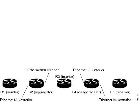
Configuring RSVP/ DiffServ Attributes on an Interior Router
The following example configures RSVP/DiffServ attributes on an interior router (R3 in the figure above).
- Ethernet interface 0/0 is enabled for RSVP and the amount of bandwidth available for reservations is configured.
- A resource provider is configured and data packet classification is disabled because RSVP aggregation supports control plane aggregation only.
Router# configure terminal
Enter configuration commands, one per line.  End with CNTL/Z.
Router(config)# interface Ethernet0/0
Router(config-if)# ip rsvp bandwidth 400
Router(config-if)# ip rsvp resource-provider none
Router(config-if)# ip rsvp data-packet classification none
Router(config-if)# end
Configuring RSVP Aggregation on an Aggregator or Deaggregator
The following example configures RSVP aggregation attributes on an aggregator or deaggregator (R2 and R4 in Figure 2
- Loopback 1 is configured to establish an RSVP aggregation router ID.
- Ethernet interface 0/0 is enabled for RSVP and the amount of bandwidth available for reservations is configured.
- Ethernet interface 0/0 on an aggregator or deaggregator is configured to face an aggregation region.
- A resource provider is configured and data packet classification is disabled because RSVP aggregation supports control plane aggregation only.
Router# configure terminal

Enter configuration commands, one per line. End with CNTL/Z.
Router(config)# interface Loopback 1
Router(config)# ip address 192.168.50.1 255.255.255.0
Router(config)# interface Ethernet0/0
Router(config-if)# ip rsvp bandwidth 400
Router(config-if)# ip rsvp aggregation role interior
Router(config-if)# ip rsvp resource-provider none
Router(config-if)# ip rsvp data-packet classification none
Router(config-if)# end
Configuring RSVP Aggregation Attributes and Parameters
The following example configures additional RSVP aggregation attributes, including a global rule for mapping all E2E reservations onto a single aggregate with DSCP AF41 and the token bucket parameters for aggregate reservations, because dynamic resizing is not supported. This configuration is only required on nodes performing the deaggregation function (R4 in the figure above).
Router# configure terminal
Enter configuration commands, one per line. End with CNTL/Z.
Router(config)# ip rsvp aggregation ip map any dscp af41
Router(config)# ip rsvp aggregation ip reservation dscp af41 aggregator 10.10.10.10 traffic-params static rate 10 burst 8 peak 10
Router(config)# end
Configuring an Access List for a Deaggregator
In the following example, access list 1 is defined for all RSVP messages whose RSVP PATH message sender template source address is in the 10.1.0.0 subnet so that the deaggregator (R4 in the figure above) maps those reservations onto an aggregate reservation for the DSCP associated with the AF41 PHB:
Router# configure terminal
Enter configuration commands, one per line. End with CNTL/Z.
Router(config)# access-list 1 permit 10.1.0.0 0.0.255.255
Router(config)# ip rsvp aggregation ip map access-list 1 dscp af41
Router(config)# end
Configuring RSVP Aggregation
After you configure your RSVP aggregation attributes, you are ready to enable aggregation globally.
When you enable aggregation on a router, the router can act as an aggregator or a deaggregator. To perform aggregator and deaggregator functions, the RSVP process must see messages with the RSVP-E2E-IGNORE protocol type (134) on a router; otherwise, the messages are forwarded as data by the router's data plane. The ip rsvp aggregation ip command enables RSVP to identify messages with the RSVP-E2E-IGNORE protocol.
Note | This registers a router to receive RSVP-E2E-IGNORE messages. It is not necessary to configure this command on interior nodes that are only processing RSVP aggregate reservations and forwarding RSVP-E2E-IGNORE messages as IP datagrams). Since the router is loaded with an image that supports aggregation, the router will process aggregate (RFC 3175 formatted) messages correctly. Enabling aggregation on an interior mode may decrease performance because the interior node will then unnecessarily process all RSVP-E2E-IGNORE messages. |
Note | If you enable aggregation on an interior node, you must configure all its interfaces as interior. Otherwise, all the interfaces have the exterior role, and any E2E PATH (E2E-IGNORE) messages arriving at the router are discarded. |
In summary, there are two options for an interior router (R3 in the figure above):
Configuring RSVP Local Policy
You can configure a local policy optionally on any RSVP capable node. In this example, a local policy is configured on a deaggregator to set the preemption priority values within the RSVP RESV aggregate messages based upon matching the DSCP within the aggregate RSVP messages session object. This allows the bandwidth available for RSVP reservations to be used first by reservations of DSCP EF over DSCP AF41 on interior or aggregation nodes. Any aggregate reservation for another DSCP will have a preemption priority of 0, the default.
Note | Within the RSVP RESV aggregate message at the deaggregator, this local policy sets an RFC 3181 "Signaled Preemption Priority Policy Element" that can be used by interior nodes or the aggregator that has ip rsvp preemption enabled. |
The following example sets the preemption priority locally for RSVP aggregate reservations during establishment on an interior router (R3 in the figure above):
Router# configure terminal
Enter configuration commands, one per line. End with CNTL/Z.
Router(config)# ip rsvp policy local dscp-ip ef
Router(config-rsvp-local-policy)# 5 5
Router(config-rsvp-local-policy)# exit
Router(config)# ip rsvp policy local dscp-ip af41
Router(config-rsvp-local-policy)# 2 2
Router(config-rsvp-local-policy)# end
Example Verifying the RSVP Aggregation Configuration
Verifying RSVP Aggregation and Configured Reservations
The following example verifies that RSVP aggregation is enabled and displays information about the reservations currently established and configured map and reservation policies:
Router# show ip rsvp aggregation ip
RFC 3175 Aggregation:  Enabled
  Level: 1
  Default QoS service: Controlled-Load
  Number of signaled aggregate reservations:  2
  Number of signaled E2E reservations:        8
  Number of configured map commands:          4
  Number of configured reservation commands:  1
Verifying Configured Interfaces and Their Roles
The following example displays the configured interfaces and whether they are interior or exterior in regard to the aggregation region:
Router# show ip rsvp aggregation ip interface
Interface Name       Role
-------------------- --------
Ethernet0/0          interior
Serial2/0            exterior
Serial3/0            exterior
Verifying Aggregator and Deaggregator Reservations
The following example displays information about the aggregators and deaggregators when established reservations are present:
Router# show ip rsvp aggregation ip endpoints detail
Role  DSCP Aggregator      Deaggregator    State  Rate    Used    QBM PoolID
----- ---- --------------- --------------- ------ ------- ------- ----------
Agg   46   10.3.3.3         10.4.4.4         ESTABL 100K    100K    0x00000003
   Aggregate Reservation for the following E2E Flows (PSBs):
To            From          Pro DPort Sport  Prev Hop       I/F      BPS
10.4.4.4      10.1.1.1       UDP 1     1     10.23.20.3     Et1/0    100K
   Aggregate Reservation for the following E2E Flows (RSBs):
To            From          Pro DPort Sport  Next Hop       I/F      Fi Serv BPS
10.4.4.4      10.1.1.1       UDP 1     1     10.4.4.4       Se2/0    FF RATE 100K
   Aggregate Reservation for the following E2E Flows (Reqs):
To            From          Pro DPort Sport  Next Hop       I/F      Fi Serv BPS
10.4.4.4      10.1.1.1       UDP 1     1     10.23.20.3     Et1/0    FF RATE 100K
Additional References
Related Documents
|
Related Topic |
Document Title |
|---|---|
|
RSVP commands: complete command syntax, command mode, command history, defaults, usage guidelines, and examples |
Cisco IOS Quality of Service Solutions Command Reference |
|
Cisco IOS commands |
|
|
QoS features including signaling, classification, and congestion management |
"Quality of Service Overview" module |
|
Information on RSVP local policies |
"RSVP Local Policy Support" module |
|
Information on RSVP scalability enhancements |
"RSVP Scalability Enhancements" module |
MIBs
RFCs
|
RFC |
Title |
|---|---|
|
RFC 2205 |
Resource ReSerVation Protocol (RSVP)--Version 1 Functional Specification |
|
RFC 2209 |
Resource ReSerVation Protocol (RSVP)--Version 1 Message Processing Rules |
|
RFC 3175 |
Aggregation of RSVP for IPv4 and IPv6 Reservations |
|
RFC 3181 |
Signaled Preemption Priority Policy Element |
|
RFC 4804 |
Aggregation of Resource ReSerVation Protocol (RSVP) Reservations over MPLS TE/DS-TE Tunnels |
Technical Assistance
|
Description |
Link |
|---|---|
|
The Cisco Support and Documentation website provides online resources to download documentation, software, and tools. Use these resources to install and configure the software and to troubleshoot and resolve technical issues with Cisco products and technologies. Access to most tools on the Cisco Support and Documentation website requires a Cisco.com user ID and password. |
Feature Information for RSVP Aggregation
The following table provides release information about the feature or features described in this module. This table lists only the software release that introduced support for a given feature in a given software release train. Unless noted otherwise, subsequent releases of that software release train also support that feature.
Use Cisco Feature Navigator to find information about platform support and Cisco software image support. To access Cisco Feature Navigator, go to www.cisco.com/go/cfn. An account on Cisco.com is not required.
| Table 1 | Feature Information for RSVP Aggregation |
|
Feature Name |
Releases |
Feature Information |
|---|---|---|
|
RSVP Aggregation |
12.2(33)SRC |
The RSVP Aggregation feature allows the Resource Reservation Protocol (RSVP) state to be reduced within an RSVP/DiffServ network by aggregating many smaller reservations into a single, larger reservation at the edge. |
Glossary
admission control --The process by which an RSVP reservation is accepted or rejected on the basis of end-to-end available network resources.
aggregate --AnRSVP flow that represents multiple end-to-end (E2E) flows; for example, a Multiprotocol Label Switching Traffic Engineering (MPLS-TE) tunnel may be an aggregate for many E2E flows.
aggregation region --An area where E2E flows are represented by aggregate flows, with aggregators and deaggregators at the edge; for example, an MPLS-TE core, where TE tunnels are aggregates for E2E flows. An aggregation region contains a connected set of nodes that are capable of performing RSVP aggregation.
aggregator --The router that processes the E2E PATH message as it enters the aggregation region. This router is also called the TE tunnel head-end router; it forwards the message from an exterior interface to an interior interface.
bandwidth --The difference between the highest and lowest frequencies available for network signals. The term is also used to describe the rated throughput capacity of a given network medium or protocol.
deaggregator --The router that processes the E2E PATH message as it leaves the aggregation region. This router is also called the TE tunnel tail-end router; it forwards the message from an interior interface to an exterior interface.
E2E --end-to-end. An RSVP flow that crosses an aggregation region, and whose state is represented in aggregate within this region, such as a classic RSVP unicast flow crossing an MPLS-TE core.
LSP --label-switched path. A configured connection between two routers, in which label switching is used to carry the packets. The purpose of an LSP is to carry data packets.
QoS --quality of service. A measure of performance for a transmission system that reflects its transmission quality and service availability.
RSVP --Resource Reservation Protocol. A protocol that supports the reservation of resources across an IP network. Applications running on IP end systems can use RSVP to indicate to other nodes the nature (bandwidth, jitter, maximum burst, and so on) of the packet streams that they want to receive.
state --Information that a router must maintain about each LSP. The information is used for rerouting tunnels.
TE --traffic engineering. The techniques and processes used to cause routed traffic to travel through the network on a path other than the one that would have been chosen if standard routing methods had been used.
tunnel --Secure communications path between two peers, such as two routers.
Cisco and the Cisco logo are trademarks or registered trademarks of Cisco and/or its affiliates in the U.S. and other countries. To view a list of Cisco trademarks, go to this URL: www.cisco.com/go/trademarks. Third-party trademarks mentioned are the property of their respective owners. The use of the word partner does not imply a partnership relationship between Cisco and any other company. (1110R)
Any Internet Protocol (IP) addresses and phone numbers used in this document are not intended to be actual addresses and phone numbers. Any examples, command display output, network topology diagrams, and other figures included in the document are shown for illustrative purposes only. Any use of actual IP addresses or phone numbers in illustrative content is unintentional and coincidental.