
 Feedback
Contents
- Marking Network Traffic
- Finding Feature Information
- Prerequisites for Marking Network Traffic
- Restrictions for Marking Network Traffic
- Information About Marking Network Traffic
- Purpose of Marking Network Traffic
- Benefits of Marking Network Traffic
- Two Methods for Marking Traffic Attributes
- Method One Using a set Command
- Method Two Using a Table Map
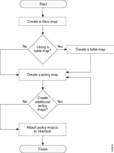
- Traffic Marking Procedure Flowchart
- MQC and Network Traffic Marking
- Traffic Classification Compared with Traffic Marking
- How to Mark Network Traffic
- Creating a Class Map for Marking Network Traffic
- Creating a Table Map for Marking Network Traffic
- Creating a Policy Map for Applying a QoS Feature to Network Traffic
- What to Do Next
- Attaching the Policy Map to an Interface
- Configuring QoS When Using IPsec VPNs
- Configuration Examples for Marking Network Traffic
- Example Creating a Class Map for Marking Network Traffic
- Example Table Map for Marking Network Traffic
- Example Policy Map for Applying a QoS Feature to Network Traffic
- Example Attaching the Policy Map to an Interface
- Example Configuring QoS When Using IPsec VPNs
- Additional References
- Feature Information for Marking Network Traffic
Marking Network Traffic
Marking network traffic allows you to set or modify the attributes for traffic (that is, packets) belonging to a specific class or category. When used in conjunction with network traffic classification, marking network traffic is the foundation for enabling many quality of service (QoS) features on your network. This module contains conceptual information and the configuration tasks for marking network traffic.
- Finding Feature Information
- Prerequisites for Marking Network Traffic
- Restrictions for Marking Network Traffic
- Information About Marking Network Traffic
- How to Mark Network Traffic
- Configuration Examples for Marking Network Traffic
- Additional References
- Feature Information for Marking Network Traffic
Finding Feature Information
Your software release may not support all the features documented in this module. For the latest feature information and caveats, see the release notes for your platform and software release. To find information about the features documented in this module, and to see a list of the releases in which each feature is supported, see the Feature Information Table at the end of this document.
Use Cisco Feature Navigator to find information about platform support and Cisco software image support. To access Cisco Feature Navigator, go to www.cisco.com/go/cfn. An account on Cisco.com is not required.
Prerequisites for Marking Network Traffic
In order to mark network traffic, Cisco Express Forwarding must be configured on both the interface receiving the traffic and the interface sending the traffic.
Restrictions for Marking Network Traffic
Traffic marking can be configured on an interface, a subinterface, or an ATM permanent virtual circuit (PVC). Marking network traffic is not supported on the following interfaces:
- Any interface that does not support Cisco Express Forwarding
- ATM switched virtual circuit (SVC)
- Fast EtherChannel
- PRI
- Tunnel
Information About Marking Network Traffic
- Purpose of Marking Network Traffic
- Benefits of Marking Network Traffic
- Two Methods for Marking Traffic Attributes
- MQC and Network Traffic Marking
- Traffic Classification Compared with Traffic Marking
Purpose of Marking Network Traffic
Traffic marking is a method used to identify certain traffic types for unique handling, effectively partitioning network traffic into different categories.
After the network traffic is organized into classes by traffic classification, traffic marking allows you to mark (that is, set or change) a value (attribute) for the traffic belonging to a specific class. For instance, you may want to change the class of service (CoS) value from 2 to 1 in one class, or you may want to change the differentiated services code point (DSCP) value from 3 to 2 in another class. In this module, these values are referred to as attributes.
Attributes that can be set and modified include the following:
- Cell loss priority (CLP) bit
- CoS value of an outgoing packet
- Discard eligible (DE) bit setting in the address field of a Frame Relay frame
- Discard-class value
- DSCP value in the type of service (ToS) byte
- MPLS EXP field value in the topmost label on either an input or an output interface
- Multiprotocol Label Switching (MPLS) experimental (EXP) field on all imposed label entries
- Precedence value in the packet header
- QoS group identifier (ID)
- ToS bits in the header of an IP packet
Benefits of Marking Network Traffic
Improved Network Performance
Traffic marking allows you to fine-tune the attributes for traffic on your network. This increased granularity helps single out traffic that requires special handling, and thus, helps to achieve optimal application performance.
Traffic marking allows you to determine how traffic will be treated, based on how the attributes for the network traffic are set. It allows you to segment network traffic into multiple priority levels or classes of service based on those attributes, as follows:
- Traffic marking is often used to set the IP precedence or IP DSCP values for traffic entering a network. Networking devices within your network can then use the newly marked IP precedence values to determine how traffic should be treated. For example, voice traffic can be marked with a particular IP precedence or DSCP and low latency queuing (LLQ) can then be configured to put all packets of that mark into a priority queue. In this case, the marking was used to identify traffic for LLQ.
- Traffic marking can be used to identify traffic for any class-based QoS feature (any feature available in policy-map class configuration mode, although some restrictions exist).
-
Traffic marking can be used to assign traffic to a QoS group within a router. The router can use the QoS groups to determine how to prioritize traffic for transmission. The QoS group value is usually used for one of the two following reasons:
- To leverage a large range of traffic classes. The QoS group value has 100 different individual markings, as opposed to DSCP and Precedence, which have 64 and 8, respectively.
- If changing the Precedence or DSCP value is undesirable.
- If a packet (for instance, in a traffic flow) needs to be marked to differentiate user-defined QoS services is leaving a router and entering a switch, the router can set the CoS value of the traffic, because the switch can process the Layer 2 CoS header marking. Alternatively, the Layer 2 CoS value of the traffic leaving a switch can be mapped to the Layer 3 IP or MPLS value.
- Weighted random early detection (WRED) uses precedence values or DSCP values to determine the probability that the traffic will be dropped. Therefore, the Precedence and DSCP can be used in conjunction with WRED.
Two Methods for Marking Traffic Attributes
There are two methods for specifying and marking traffic attributes:
- You can specify and mark the traffic attribute by using a set command.
With this method, you configure individual set commands for the traffic attribute that you want to mark.
- You can specify and mark the traffic attribute by creating a mapping table (called a "table map").
With this method, you configure the traffic attributes that you want to mark once in a table map and then the markings can be propagated throughout the network.
These methods are further described in the sections that follow.
Method One Using a set Command
You specify the traffic attribute you want to change with a setcommand configured in a policy map. The table below lists the available setcommands and the corresponding attribute. The table also includes the network layer and the network protocol typically associated with the traffic attribute.
| Table 1 | set Commands and Corresponding Traffic Attribute, Network Layer, and Protocol |
|
set Commands1 |
Traffic Attribute |
Network Layer |
Protocol |
|---|---|---|---|
|
set atm-clp |
CLP bit |
Layer 2 |
ATM |
|
set cos |
Layer 2 CoS value of the outgoing traffic |
Layer 2 |
ATM, Frame Relay |
|
set discard-class |
discard-class value |
Layer 2 |
ATM, Frame Relay |
|
set dscp |
DSCP value in the ToS byte |
Layer 3 |
IP |
|
set fr-de |
DE bit setting in the address field of a Frame Relay frame |
Layer 2 |
Frame Relay |
|
set ip tos (route-map) |
ToS bits in the header of an IP packet |
Layer 3 |
IP |
|
set mpls experimental imposition |
MPLS EXP field on all imposed label entries |
Layer 3 |
MPLS |
|
set mpls experimental topmost |
MPLS EXP field value in the topmost label on either an input or an output interface |
Layer 3 |
MPLS |
|
set precedence |
precedence value in the packet header |
Layer 3 |
IP |
|
set qos-group |
QoS group ID |
Layer 3 |
IP, MPLS |
If you are using individual set commands, those set commands are specified in a policy map. The following is a sample of a policy map configured with one of the set commands listed in the table above.
In this sample configuration, the set atm-clpcommand has been configured in the policy map (policy1) to mark the CLP attribute.
 policy-map policy1
  class class1
  set atm-clp
  end
Method Two Using a Table Map
You can create a table map that can be used to mark traffic attributes. A table map is a kind of two-way conversion chart that lists and maps one traffic attribute to another. A table map supports a many-to-one type of conversion and mapping scheme. The table map establishes a to-from relationship for the traffic attributes and defines the change to be made to the attribute. That is, an attribute is set to one value that is taken from another value. The values are based on the specific attribute being changed. For instance, the Precedence attribute can be a number from 0 to 7, while the DSCP attribute can be a number from 0 to 63.
The following is a sample table map configuration:
table-map table-map1
map from 0 to 1
map from 2 to 3
exit
The table below lists the traffic attributes for which a to-from relationship can be established using the table map.
| Table 2 | Traffic Attributes for Which a To-From Relationship Can Be Established |
|
The "To" Attribute |
The "From" Attribute |
|---|---|
|
Precedence |
CoS |
|
QoS group |
|
|
DSCP |
CoS |
|
QoS group |
|
|
CoS |
Precedence |
|
DSCP |
|
|
QoS group |
Precedence |
|
DSCP |
|
|
MPLS EXP topmost |
|
|
MPLS EXP topmost |
QoS group |
|
MPLS EXP imposition |
Precedence |
|
DSCP |
Once the table map is created, you configure a policy map to use the table map. In the policy map, you specify the table map name and the attributes to be mapped by using the table keyword and the table-map-name argument with one of the commands listed in the table below.
| Table 3 | Commands Used in Policy Maps to Map Attributes |
|
Command Used in Policy Maps |
Maps These Attributes |
|---|---|
|
set cos dscp table table-map-name |
CoS to DSCP |
|
set cos precedence table table-map-name |
CoS to Precedence |
|
set dscp cos table table-map-name |
DSCP to CoS |
|
set dscp qos-group table table-map-name |
DSCP to qos-group |
|
set mpls experimental imposition dscp table table-map-name |
MPLS EXP imposition to DSCP |
|
set mpls experimental imposition precedence table table-map-name |
MPLS EXP imposition to precedence |
|
set mpls experimental topmost qos-group table table-map-name |
MPLS EXP topmost to QoS-group |
|
set precedence cos table table-map-name |
Precedence to CoS |
|
set precedence qos-group table table-map-name |
Precedence to QoS-group |
|
set qos-group dscp table table-map-name |
QoS-group to DSCP |
|
set qos-group mpls exp topmost table table-map-name |
QoS-group to MPLS EXP topmost |
|
set qos-group precedence table table-map-name |
QoS-group to Precedence |
The following is an example of a policy map (policy2) configured to use the table map (table-map1) created earlier:
policy map policy2
class class-default
set cos dscp table table-map1
exit
In this example, a mapping relationship was created between the CoS attribute and the DSCP attribute as defined in the table map.
MQC and Network Traffic Marking
To configure network traffic marking, you use the Modular Quality of Service (QoS) Command-Line Interface (CLI) (MQC).
The MQC is a CLI structure that allows you to complete the following tasks:
- Specify the matching criteria used to define a traffic class.
- Create a traffic policy (policy map). The traffic policy defines the QoS policy actions to be taken for each traffic class.
- Apply the policy actions specified in the policy map to an interface, subinterface, or ATM PVC by using the service-policy command.
Traffic Classification Compared with Traffic Marking
Traffic classification and traffic marking are closely related and can be used together. Traffic marking can be viewed as an additional action, specified in a policy map, to be taken on a traffic class.
Traffic classification allows you to organize into traffic classes on the basis of whether the traffic matches specific criteria. For example, all traffic with a CoS value of 2 is grouped into one class, and traffic with DSCP value of 3 is grouped into another class. The match criterion is user-defined.
After the traffic is organized into traffic classes, traffic marking allows you to mark (that is, set or change) an attribute for the traffic belonging to that specific class. For instance, you may want to change the CoS value from 2 to 1, or you may want to change the DSCP value from 3 to 2.
The match criteria used by traffic classification are specified by configuring a match command in a class map. The marking action taken by traffic marking is specified by configuring a set command in a policy map. These class maps and policy maps are configured using the MQC.
The table below compares the features of traffic classification and traffic marking.
| Table 4 | Traffic Classification Compared with Traffic Marking |
|
Traffic Classification |
Traffic Marking |
|
|---|---|---|
|
Goal |
Groups network traffic into specific traffic classes on the basis of whether the traffic matches the user-defined criterion. |
After the network traffic is grouped into traffic classes, modifies the attributes for the traffic in a particular traffic class. |
|
Configuration Mechanism |
Uses class maps and policy maps in the MQC. |
Uses class maps and policy maps in the MQC. |
|
CLI |
In a class map, uses match commands (for example, match cos) to define the traffic matching criterion. |
Uses the traffic classes and matching criterion specified by traffic classification. In addition, uses set commands (for example, set cos) in a policy map to modify the attributes for the network traffic. If a table map was created, uses the table keyword and table-map-name argument with the set commands (for example, set cos precedence table table-map-name) in the policy map to establish the to-from relationship for mapping attributes. |
How to Mark Network Traffic
- Creating a Class Map for Marking Network Traffic
- Creating a Table Map for Marking Network Traffic
- Creating a Policy Map for Applying a QoS Feature to Network Traffic
- Attaching the Policy Map to an Interface
- Configuring QoS When Using IPsec VPNs
Creating a Class Map for Marking Network Traffic
DETAILED STEPS
Creating a Table Map for Marking Network Traffic
 Note | If you are not using a table map, skip this procedure and advance to Creating a Policy Map for Applying a QoS Feature to Network Traffic. |
DETAILED STEPS
| Command or Action | Purpose | |
|---|---|---|
Step 1 |
enable
Example: Router> enable |
Enables privileged EXEC mode. |
Step 2 |
configure
terminal
Example: Router# configure terminal |
Enters global configuration mode. |
Step 3 |
table-map
table-map-name
map
from
from-value
to
to-value
[default default-action-or-value]
Example:
Example: Router(config)# table-map table-map1 map from 2 to 1 |
Creates a table map using the specified name and enters tablemap configuration mode.
|
Step 4 |
end
Example: Router(config-tablemap)# end |
(Optional) Exits tablemap configuration mode and returns to privileged EXEC mode. |
Creating a Policy Map for Applying a QoS Feature to Network Traffic
Note |
|
DETAILED STEPS
| Command or Action | Purpose | |||
|---|---|---|---|---|
Step 1 |
enable
Example: Router> enable |
Enables privileged EXEC mode.
| ||
Step 2 |
configure
terminal
Example: Router# configure terminal |
Enters global configuration mode. | ||
Step 3 |
policy-map
policy-map-name
Example: Router(config)# policy-map policy1 |
Specifies the name of the policy map created earlier and enters policy-map configuration mode.
| ||
Step 4 |
class
{class-name | class-default} Example: Router(config-pmap)# class class1 |
Specifies the name of the class whose policy you want to create and enters policy-map class configuration mode. This class is associated with the class map created earlier.
| ||
Step 5 |
set
cos
cos-value
Example:
|
(Optional) Sets the CoS value in the type of service (ToS) byte.
| ||
Step 6 |
or | |||
Step 7 |
set
cos
dscp
table
table-map-name
Example:
|
(Optional) If a table map has been created earlier, sets the CoS value based on the DSCP value (or action) defined in the table map.
| ||
Step 8 |
Router(config-pmap-c)# set cos 2 | |||
Step 9 | ||||
Step 10 |
Router(config-pmap-c)#
set cos dscp table table-map1 | |||
Step 11 |
end
Example: Router(config-pmap-c)# end |
Returns to privileged EXEC mode. | ||
Step 12 |
show
policy-map
|
(Optional) Displays all configured policy maps. | ||
Step 13 |
or | |||
Step 14 |
show
policy-map
policy-map
class
class-name
Example:
|
(Optional) Displays the configuration for the specified class of the specified policy map.
| ||
Step 15 |
Router# show policy-map | |||
Step 16 | ||||
Step 17 |
Router#
show policy-map policy1 class class1 | |||
Step 18 |
exit
Example: Router# exit |
(Optional) Exits privileged EXEC mode. |
What to Do Next
Create and configure as many policy maps as you need for your network. To create and configure additional policy maps, repeat the steps in the Creating a Policy Map for Applying a QoS Feature to Network Traffic. Then attach the policy maps to the appropriate interface, following the instructions in the Attaching the Policy Map to an Interface.
Attaching the Policy Map to an Interface
Note | Depending on the needs of your network, policy maps can be attached to an interface, a subinterface, or an ATM permanent virtual circuit (PVC). |
DETAILED STEPS
| Command or Action | Purpose | |||
|---|---|---|---|---|
Step 1 |
enable
Example: Router> enable |
Enables privileged EXEC mode. | ||
Step 2 |
configure
terminal
Example: Router# configure terminal |
Enters global configuration mode. | ||
Step 3 |
interface
type
number
[name-tag]
Example: Router(config)# interface serial4/0 |
Configures an interface type and enters interface configuration mode. | ||
Step 4 |
pvc
[name]
vpi / vci
[ilmi|qsaal|smds|
l2transport]
Example: Router(config-if)# pvc cisco 0/16 |
(Optional) Creates or assigns a name to an ATM permanent virtual circuit (PVC), specifies the encapsulation type on an ATM PVC, and enters ATM virtual circuit configuration mode.
| ||
Step 5 |
exit
Example: Router(config-atm-vc)# exit |
(Optional) Returns to interface configuration mode.
| ||
Step 6 |
service-policy
{input |
output} policy-map-name Example: Router(config-if)# service-policy input policy1 |
Attaches a policy map to an input or output interface.
| ||
Step 7 |
end
Example: Router(config-if)# end |
Returns to privileged EXEC mode. | ||
Step 8 |
show
policy-map
interface
type
number
Example: Router# show policy-map interface serial4/0 |
(Optional) Displays traffic statistics of all classes configured for all service policies on the specified interface, subinterface, or PVC on the interface. When there are multiple instances of the same class in a policy-map, and this policy-map is attached to an interface,
show policy-map interface <interface_name> output class <class-name>
returns only the first instance. | ||
Step 9 |
exit
Example: Router# exit |
(Optional) Exits privileged EXEC mode. |
Configuring QoS When Using IPsec VPNs
Note | This task is required only if you are using IPsec Virtual Private Networks (VPNs). Otherwise, this task is not necessary. For information about IPsec VPNs, see the "Configuring Security for VPNs with IPsec" module. |
Note | This task uses the qos pre-classify command to enable QoS preclassification for the packet. QoS preclassification is not supported for all fragmented packets. If a packet is fragmented, each fragment might received different preclassifications. > |
DETAILED STEPS
| Command or Action | Purpose | |
|---|---|---|
Step 1 |
enable
Example: Router> enable |
Enables privileged EXEC mode. |
Step 2 |
configure
terminal
Example: Router# configure terminal |
Enters global configuration mode. |
Step 3 |
crypto
map
map-name
seq-num
Example: Router(config)# crypto map mymap 10 |
Enters crypto map configuration mode and creates or modifies a crypto map entry. |
Step 4 |
exit
Example: Router(config-crypto-map)# exit |
Returns to global configuration mode. |
Step 5 |
interface
type
number
[name-tag]
Example: Router(config)# interface serial4/0 |
Configures an interface type and enters interface configuration mode. |
Step 6 |
qos
pre-classify
Example: Router(config-if)# qos pre-classify |
Enables QoS preclassification. |
Step 7 |
end
Example: Router(config-if)# end |
(Optional) Exits interface configuration mode and returns to privileged EXEC mode. |
Configuration Examples for Marking Network Traffic
- Example Creating a Class Map for Marking Network Traffic
- Example Table Map for Marking Network Traffic
- Example Policy Map for Applying a QoS Feature to Network Traffic
- Example Attaching the Policy Map to an Interface
- Example Configuring QoS When Using IPsec VPNs
Example Creating a Class Map for Marking Network Traffic
The following is an example of creating a class map to be used for marking network traffic. In this example, a class called class1 has been created. The traffic with a Frame Relay DLCI value of 500 will be put in this class.
Router> enable
Router# configure terminal
Router(config)# class-map class1
Router(config-cmap)# match fr-dlci 500
Router(config-cmap)# end
Example Table Map for Marking Network Traffic
In the following example, the table-map (value mapping) command has been used to create and configure a table map called table-map1. This table map will be used to establish a to-from relationship between one traffic-marking value and another.
In table-map1, a traffic-marking value of 0 will be mapped to a value of 1.
Router> enable
Router# configure terminal
Router(config)# table-map
 table-map1 map from 0 to 1
Router(config-tablemap)#
 end
Example Policy Map for Applying a QoS Feature to Network Traffic
Policy Map Configured to Use set Command
The following is an example of creating a policy map to be used for traffic marking. In this example, a policy map called policy1 has been created, and the set dscpcommand has been configured for class1.
Router> enable
Router# configure terminal
Router(config)# policy-map policy1
Router(config-pmap)# class class1
Router(config-pmap-c)# set dscp 2
Router(config-pmap-c)# end
Policy Map Configured to Use a Table Map
A policy map called policy1 has been created and configured to use table-map1 for setting the precedence value. In this example, the CoS value will be set according to the DSCP value defined in table-map1 created previously.
Router(config)# policy map policy1
Router(config-pmap)# class class-default
Router(config-pmap-c)#
 set cos dscp table table-map1
Router(config-pmap-c)#
 end
Note | As an alternative to configuring the set cos dscp table table-map1 command shown in the example, you could configure the command without specifying the table keyword and the applicable table-map-name argument (that is, you could configure the set cos dscpcommand). When the command is configured without the table keyword and applicable table map name, the values are copied from the specified categories. In this case, the DSCP value is copied and used to set the CoS value. When the DSCP value is copied and used for the CoS value only the first 3 bits (that is, the class selector bits) of the DSCP value will be used to set the CoS value. For example, if the DSCP value is EF (101110), the first 3 bits of this DSCP value will be used to set the CoS value, resulting in a CoS value of 5 (101). |
Policy Map Configured to Use a Table Map for Mapping MPLS EXP Values
This section contains an example of a policy map configured to map MPLS experimental (EXP) values. The figure below illustrates the network topology for this configuration example.
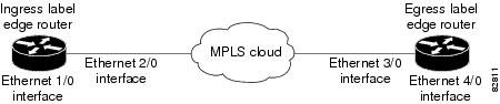
For this configuration example, traffic arrives at the input interface (an Ethernet 1/0 interface) of the ingress label edge router (LER). The precedence value is copied and used as the MPLS EXP value of the traffic when the MPLS label is imposed. This label imposition takes place at the ingress LER.
The traffic leaves the ingress LER through the output interface (an Ethernet 2/0 interface), traverses through the network backbone into the MPLS cloud, and enters the egress LER.
At the input interface of the egress LER (an Ethernet 3/0 interface), the MPLS EXP value is copied and used as the QoS group value. At the output interface of the egress LER (an Ethernet 4/0 interface), the QoS group value is copied and used as the precedence value.
To accomplish configuration described above, three separate policy maps were required--policy1, policy2, and policy3. Each policy map is configured to convert and propagate different traffic-marking values.
The first policy map, policy1, is configured to copy the precedence value of the traffic and use it as the MPLS EXP value during label imposition.
Router(config)# policy-map policy1
Router(config-pmap)# class class-default
Router(config-pmap-c)#
 set mpls experimental imposition precedence
Router(config-pmap-c)#
 end
When the traffic leaves the LER through the output interface (the Ethernet 2/0 interface), the MPLS EXP value is copied from the precedence value during MPLS label imposition. Copying the MPLS EXP value from the precedence value ensures that the MPLS EXP value reflects the appropriate QoS treatment. The traffic now proceeds through the MPLS cloud into the egress LER.
A second policy map called policy2 has been configured to copy the MPLS EXP value in the incoming MPLS traffic to the QoS group value. The QoS group value is used for internal purposes only. The QoS group value can be used with output queueing on the output interface of the egress router. The QoS group value can also be copied and used as the precedence value, as traffic leaves the egress LER through the output interface (the Ethernet 4/0 interface).
Router(config)# policy-map policy2
Router(config-pmap)# class class-default
Router(config-pmap-c)#
 set qos-group mpls experimental topmost
Router(config-pmap-c)#
 end
A third policy map called policy3 has been configured to copy the internal QoS group value (previously based on the MPLS EXP value) to the precedence value. The QoS group value will be copied to the precedence value as the traffic leaves the egress LER through the output interface.
Router(config)# policy-map policy3
Router(config-pmap)# class class-default
Router(config-pmap-c)#
 set precedence qos-group
Router(config-pmap-c)#
 end
Configuring these policy maps as shown (and attaching them to interfaces as shown in Example Attaching the Policy Map to an Interface), causes the appropriate quality of service treatment to be preserved for the traffic as the traffic progresses along an IP network, through an MPLS cloud, and back again into an IP network.
Note | This configuration could also have been accomplished by first creating a table map (used to map one value to another) and then specifying the table keyword and table-map-name argument in each of the set commands (for example, set precedence qos-group table tablemap1). In the MPLS configuration example, a table map was not created, and the set commands were configured without specifying the table keyword and table-map-name argument (for example, set precedence qos-group). When the set commands are configured without specifying the table keyword and table-map-name argument, the values are copied from the specified categories. In this case, the QoS group value was copied and used to set the precedence value. When the DSCP value is copied and used for the MPLS EXP value, only the first 3 bits (that is, the class selector bits) of the DSCP value will be used to set the MPLS value. |
Example Attaching the Policy Map to an Interface
The following is an example of attaching the policy map to the interface. In this example, the policy map called policy1 has been attached in the input direction of the Serial4/0 interface.
Router> enable
Router# configure terminal
Router(config)# interface serial4/0
Router(config-if)# service-policy input policy1
Router(config-if)# end
Example Configuring QoS When Using IPsec VPNs
The following is an example of configuring QoS when using IPsec VPNs. In this example, the crypto map command specifies the IPsec crypto map (mymap 10) to which the qos pre-classify command will be applied.
Router> enable
Router# configure terminal
Router(config)# crypto map mymap 10

Router(config-crypto-map)# qos pre-classify
Router(config-crypto-map)# exit
Additional References
Related Documents
|
Related Topic |
Document Title |
|---|---|
|
Cisco IOS commands |
|
|
QoS commands: complete command syntax, command modes, command history, defaults, usage guidelines, and examples |
Cisco IOS Quality of Service Solutions Command Reference |
|
MQC |
"Applying QoS Features Using the MQC" module |
|
Classifying network traffic |
"Classifying Network Traffic" module |
|
IPsec and VPNs |
"Configuring Security for VPNs with IPsec" module |
|
Committed Access Rate (CAR) |
"Configuring Committed Access Rate" module |
|
IPv6 QoS |
"IPv6 Quality of Service" module |
|
IPv6 MQC Packet Marking and Remarking |
"IPv6 QoS: MQC Packet Marking/Remarking" module |
MIBs
Technical Assistance
|
Description |
Link |
|---|---|
|
The Cisco Support and Documentation website provides online resources to download documentation, software, and tools. Use these resources to install and configure the software and to troubleshoot and resolve technical issues with Cisco products and technologies. Access to most tools on the Cisco Support and Documentation website requires a Cisco.com user ID and password. |
Feature Information for Marking Network Traffic
The following table provides release information about the feature or features described in this module. This table lists only the software release that introduced support for a given feature in a given software release train. Unless noted otherwise, subsequent releases of that software release train also support that feature.
Use Cisco Feature Navigator to find information about platform support and Cisco software image support. To access Cisco Feature Navigator, go to www.cisco.com/go/cfn. An account on Cisco.com is not required.
| Table 5 | Feature Information for Marking Network Traffic |
|
Feature Name |
Software Releases |
Feature Configuration Information |
|---|---|---|
|
Enhanced Packet Marking |
12.2(13)T |
The Enhanced Packet Marking feature allows you to map and convert the marking of a packet from one value to another by using a kind of conversion chart called a table map. The table map establishes an equivalency from one value to another. For example, the table map can map and convert the class of service (CoS) value of a packet to the precedence value of the packet. This value mapping can be propagated for use on the network, as needed. |
|
QoS Packet Marking |
12.2(8)T |
The QoS Packet Marking feature allows you to mark packets by setting the IP precedence bit or the IP differentiated services code point (DSCP) in the Type of Service (ToS) byte, and associate a local QoS group value with a packet. |
|
Class-Based Marking |
12.2(2)T |
The Class-Based Packet Marking feature provides users with a user-friendly command-line interface (CLI) for efficient packet marking by which users can differentiate packets based on the designated markings. |
|
Quality of Service for Virtual Private Networks |
12.2(2)T |
The QoS for VPNs feature provides a solution for making Cisco IOS QoS services operate in conjunction with tunneling and encryption on an interface. Cisco IOS software can classify packets and apply the appropriate QoS service before the data is encrypted and tunneled. The QoS for VPN feature allows users to look inside the packet so that packet marking can be done based on original port numbers and based on source and destination IP addresses. This allows the service provider to treat mission critical or multi-service traffic with higher priority across their network. |
|
ATM Cell Loss Priority (CLP) Setting Class-Based Ethernet CoS Matching and Marking (802.1p and ISL CoS) Class-Based Marking Custom Queueing (CQ) PXF Based Frame Relay DE Bit Marking QoS Packet Marking |
15.0(1)S |
The ATM Cell Loss Priority (CLP) Setting, Class-Based Ethernet CoS Matching and Marking (802.1p and ISL CoS), Class-Based Marking, Custom Queueing (CQ), PXF Based Frame Relay DE Bit Marking, QoS Packet Marking and features were integrated into theCisco IOS Release 15.0(1)S release. |
Cisco and the Cisco Logo are trademarks of Cisco Systems, Inc. and/or its affiliates in the U.S. and other countries. A listing of Cisco's trademarks can be found at www.cisco.com/go/trademarks. Third party trademarks mentioned are the property of their respective owners. The use of the word partner does not imply a partnership relationship between Cisco and any other company. (1005R)
Any Internet Protocol (IP) addresses and phone numbers used in this document are not intended to be actual addresses and phone numbers. Any examples, command display output, network topology diagrams, and other figures included in the document are shown for illustrative purposes only. Any use of actual IP addresses or phone numbers in illustrative content is unintentional and coincidental.