
 Feedback
Contents
- Configuring MPLS Egress NetFlow Accounting and Analysis
- Finding Feature Information
- Prerequisites for Configuring MPLS Egress NetFlow Accounting
- Restrictions for Configuring MPLS Egress NetFlow Accounting
- Information About Configuring MPLS Egress NetFlow Accounting
- MPLS Egress NetFlow Accounting Benefits Enhanced Network Monitoring and More Accurate Accounting Statistics
- MPLS VPN Flow Capture with MPLS Egress NetFlow Accounting
- How to Configure MPLS Egress NetFlow Accounting
- Configuring MPLS Egress NetFlow Accounting
- Troubleshooting Tips
- Verifying MPLS Egress NetFlow Accounting Configuration
- Configuration Examples for Configuring MPLS Egress NetFlow Accounting
- Enabling MPLS Egress NetFlow Accounting Example
- Additional References
- Feature Information for Configuring MPLS Egress NetFlow Accounting
- Glossary
Configuring MPLS Egress NetFlow Accounting and Analysis
This module contains information about and instructions for configuring the MPLS Egress NetFlow Accounting feature. The MPLS Egress NetFlow Accounting feature allows you to capture IP flow information for packets that are undergoing MPLS label disposition; that is, packets that arrive on a router as MPLS packets and that are transmitted as IP packets.
NetFlow is a Cisco IOS application that provides statistics on packets flowing through the router. It is emerging as a primary network accounting and security technology.
- Finding Feature Information
- Prerequisites for Configuring MPLS Egress NetFlow Accounting
- Restrictions for Configuring MPLS Egress NetFlow Accounting
- Information About Configuring MPLS Egress NetFlow Accounting
- How to Configure MPLS Egress NetFlow Accounting
- Configuration Examples for Configuring MPLS Egress NetFlow Accounting
- Additional References
- Feature Information for Configuring MPLS Egress NetFlow Accounting
- Glossary
Finding Feature Information
Your software release may not support all the features documented in this module. For the latest feature information and caveats, see the release notes for your platform and software release. To find information about the features documented in this module, and to see a list of the releases in which each feature is supported, see the Feature Information Table at the end of this document.
Use Cisco Feature Navigator to find information about platform support and Cisco software image support. To access Cisco Feature Navigator, go to www.cisco.com/go/cfn. An account on Cisco.com is not required.
Prerequisites for Configuring MPLS Egress NetFlow Accounting
The network must support the following Cisco IOS features before you enable the MPLS Egress NetFlow Accounting feature:
- Multiprotocol label switching (MPLS)
Before you can configure the MPLS Egress NetFlow Accounting feature, you must:
- Configure the router for IP routing
- Configure Cisco Express Forwarding (CEF) switching or distributed CEF (dCEF) switching on the router and on the interfaces that you want to enable MPLS Egress NetFlow Accounting on (fast switching is not supported)
Restrictions for Configuring MPLS Egress NetFlow Accounting
The MPLS Egress NetFlow Accounting feature is not supported in Cisco IOS Release 12.2(25)S and later. Use the Egress NetFlow Accounting feature, which captures either IP or MPLS packets as they leave the router.
Capturing Flows from Sites that Connect to the Same PE Router
The captured egress flows must originate from different sites of the same Virtual Private Network (VPN), and they cannot connect to the same provider edge (PE) router. If both source and destination VPN sites are connected to the PE router, the MPLS egress NetFlow accounting feature does not capture these egress flows. You can capture these flows by enabling ingress NetFlow on the incoming customer edge (CE)-PE link of the PE router. For example, in the figure below, traffic from site 3 (VPN1 destined for site 2) is captured by an ingress NetFlow enabled on the PE2-CE3 link of PE2.
Information About Configuring MPLS Egress NetFlow Accounting
- MPLS Egress NetFlow Accounting Benefits Enhanced Network Monitoring and More Accurate Accounting Statistics
- MPLS VPN Flow Capture with MPLS Egress NetFlow Accounting
MPLS Egress NetFlow Accounting Benefits Enhanced Network Monitoring and More Accurate Accounting Statistics
Enhanced Network Monitoring for Complete Billing Solution
You can now capture flows on the egress and ingress router interfaces and obtain complete end-to-end usage information on network traffic. The accounting server uses the collected data for various levels of aggregation for accounting reports and application programming interface (API) accounting information, thus providing a complete billing solution.
MPLS VPN Flow Capture with MPLS Egress NetFlow Accounting
The MPLS Egress NetFlow Accounting feature allows you to capture IP flow information for packets that arrive on a router as MPLS packets and are transmitted as IP packets.
This feature allows you to capture the MPLS Virtual Private Network (VPN) IP flows that are traveling through the service provider backbone from one site of a VPN to another site of the same VPN.
Formerly, you could capture flows only for IP packets on the ingress interface of a router. You could not capture flows for MPLS encapsulated frames, which were switched through CEF from the input port. Therefore, in an MPLS VPN environment, you captured flow information when packets were received from a customer edge (CE) router and forwarded to the backbone. However, you could not capture flow information when packets were transmitted to a CE router because those packets were received as MPLS frames.
The MPLS Egress NetFlow Accounting feature lets you capture the flows on the outgoing interfaces.
The figure below shows a sample MPLS VPN network topology that includes four VPN 1 sites and two VPN 2 sites. If MPLS egress NetFlow is enabled on an outgoing PE interface, you can capture IP flow information for packets that arrive at the PE as MPLS packets (from an MPLS VPN) and that are transmitted as IP packets. For example,
- To capture the flow of traffic going to site 2 of VPN 1 from any remote VPN 1 sites, you enable MPLS egress NetFlow on link PE2-CE5 of provider edge router PE2.
- To capture the flow of traffic going to site 1 of VPN 2 from any remote VPN 2 site, you enable MPLS egress NetFlow on link PE3-CE4 of the provider edge router PE3.
The flows are stored in a global flow cache maintained by the router. You can use the show ip cache flow command or other aggregation flow commands to view the egress flow data.
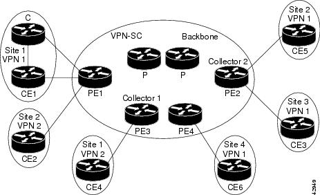
The PE routers export the captured flows to the configured collector devices in the provider network. Applications such as the Network Data Analyzer or the VPN Solution Center (VPN-SC) can gather information from the captured flows and compute and display site-to-site VPN traffic statistics.
How to Configure MPLS Egress NetFlow Accounting
Configuring MPLS Egress NetFlow Accounting
DETAILED STEPS
Verifying MPLS Egress NetFlow Accounting Configuration
Perform the steps in this optional task to verify that the MPLS Egress NetFlow Accounting configuration is as you expect.
DETAILED STEPS
Configuration Examples for Configuring MPLS Egress NetFlow Accounting
Enabling MPLS Egress NetFlow Accounting Example
This section contains a sample configuration for the MPLS Egress NetFlow Accounting feature.
The show ip vrfcommand lists the Virtual Private Network (VPN) routing and forwarding instances (VRFs) configured in the router:
Router# show ip vrf
  Name                             Default RD          Interfaces
  vpn1                             100:1               Ethernet1/4
                                                       Loopback1
  vpn3                             300:1               Ethernet1/2
                                                       Loopback2
In the following example, MPLS Egress NetFlow Accounting is enabled on interface Ethernet 1/4:
configure terminal
!
interface ethernet 1/4
 ip address 172.17.24.2 255.255.255.0
 mpls netflow egress
 exit
Enter the show running-configcommand to view the current configuration in the router:
Router# show running-config
Building configuration...
Current configuration:
!
version 12.0
service timestamps debug uptime
service timestamps log uptime
no service password-encryption
ip cef
no ip domain-lookup
!
This section of the output shows the VRF being defined and shows that the MPLS Egress NetFlow Accounting feature is enabled:
ip vrf vpn1
 rd 100:1
 route-target export 100:1
 route-target import 100:1
!
interface Loopback0
 ip address 10.41.41.41 255.255.255.255
 no ip directed-broadcast
 no ip mroute-cache
!
interface Ethernet1/4
 ip vrf forwarding vpn1
 ip address 172.17.24.2 255.255.255.0
 no ip directed-broadcast
 mpls netflow egress
!
Additional References
Related Documents
|
Related Topic |
Document Title |
|---|---|
|
Overview of Cisco IOS NetFlow |
Cisco IOS NetFlow Overview |
|
The minimum information about and tasks required for configuring NetFlow and NetFlow Data Export |
Getting Started with Configuring NetFlow and NetFlow Data Export |
|
Tasks for configuring NetFlow to capture and export network traffic data |
Configuring NetFlow and NetFlow Data Export |
|
Tasks for configuring Configuring MPLS Aware NetFlow |
Configuring MPLS Aware NetFlow |
|
Tasks for configuring NetFlow input filters |
Using NetFlow Filtering or Sampling to Select the Network Traffic to Track |
|
Tasks for configuring Random Sampled NetFlow |
Using NetFlow Filtering or Sampling to Select the Network Traffic to Track |
|
Tasks for configuring NetFlow aggregation caches |
Configuring NetFlow Aggregation Caches |
|
Tasks for configuring NetFlow BGP next hop support |
Configuring NetFlow BGP Next Hop Support for Accounting and Analysis |
|
Tasks for configuring NetFlow multicast support |
Configuring NetFlow Multicast Accounting |
|
Tasks for detecting and analyzing network threats with NetFlow |
Detecting and Analyzing Network Threats With NetFlow |
|
Tasks for configuring NetFlow Reliable Export With SCTP |
NetFlow Reliable Export With SCTP |
|
Tasks for configuring NetFlow Layer 2 and Security Monitoring Exports |
NetFlow Layer 2 and Security Monitoring Exports |
|
Tasks for configuring the SNMP NetFlow MIB |
Configuring SNMP and using the NetFlow MIB to Monitor NetFlow Data |
|
Tasks for configuring the NetFlow MIB and Top Talkers feature |
Configuring NetFlow Top Talkers using Cisco IOS CLI Commands or SNMP Commands |
|
Information for installing, starting, and configuring the CNS NetFlow Collection Engine |
MIBs
Technical Assistance
|
Description |
Link |
|---|---|
|
The Cisco Support website provides extensive online resources, including documentation and tools for troubleshooting and resolving technical issues with Cisco products and technologies. To receive security and technical information about your products, you can subscribe to various services, such as the Product Alert Tool (accessed from Field Notices), the Cisco Technical Services Newsletter, and Really Simple Syndication (RSS) Feeds. Access to most tools on the Cisco Support website requires a Cisco.com user ID and password. |
Feature Information for Configuring MPLS Egress NetFlow Accounting
The following table provides release information about the feature or features described in this module. This table lists only the software release that introduced support for a given feature in a given software release train. Unless noted otherwise, subsequent releases of that software release train also support that feature.
Use Cisco Feature Navigator to find information about platform support and Cisco software image support. To access Cisco Feature Navigator, go to www.cisco.com/go/cfn. An account on Cisco.com is not required.
| Table 1 | Feature Information for Configuring MPLS Egress NetFlow Accounting |
|
Feature Name |
Releases |
Feature Configuration Information |
|---|---|---|
|
MPLS Egress NetFlow Accounting |
12.1(5)T 12.0(20)S |
The MPLS Egress NetFlow Accounting feature allows you to capture IP flow information for packets that are undergoing MPLS label disposition; that is, packets that arrive on a router as MPLS packets and that are transmitted as IP packets. The following commands were introduced or modified by this feature: debug mpls netflow, mpls netflow egress, show mpls forwarding-table, and show mpls interface. |
Glossary
BGP --Border Gateway Protocol. An interdomain routing protocol that replaces Exterior Gateway Protocol (EGP). A BGP system exchanges reachability information with other BGP systems. BGP is defined by RFC 1163.
BGP/MPLS/VPN --A Virtual Private Network (VPN) solution that uses Multiprotocol Label Switching (MPLS) and Border Gateway Protocol (BGP) to allow multiple remote customer sites to be connected over an IP backbone. Refer to RFC 2547 for details.
CE router --A customer edge router. A router that is part of a customer network and interfaces to a provider edge (PE) router.
customer network --A network that is under the control of an end customer. A customer network can use private addresses as defined in RFC 1918. Customer networks are logically isolated from each other and from the provider network. A customer network is also known as a C network.
egress PE --The provider edge router through which traffic moves from the backbone to the destination Virtual Private Network (VPN) site.
flow --A set of packets with the same source IP address, destination IP address, source/destination ports, and type-of-service, and the same interface on which flow is monitored. Ingress flows are associated with the input interface, and egress flows are associated with the output interface.
ingress PE --The provider edge router through which traffic enters the backbone (provider network) from a Virtual Private Network (VPN) site.
label --A short, fixed length identifier that tells switching nodes how the data (packets or cells) should be forwarded.
MPLS --Multiprotocol Label Switching. An emerging industry standard for the forwarding of packets along normally routed paths (sometimes called MPLS hop-by-hop forwarding).
PE route r--A provider edge router. A router at the edge of a provider network that interfaces to customer edge (CE) routers.
provider network --A backbone network that is under the control of a service provider and provides transport among customer sites. A provider network is also known as the P network.
VPN --Virtual Private Network. The result of a router configuration that enables IP traffic to use tunneling to travel securely over a public TCP/IP network.
VRF --Virtual Private Network (VPN) routing/forwarding instance. The VRF is a key element in the MPLS VPN technology. VRFs exist on PEs only. A VRF is populated with VPN routes and allows one PE to have multiple routing tables. One VRF is required per VPN on each PE in the VPN.
Cisco and the Cisco logo are trademarks or registered trademarks of Cisco and/or its affiliates in the U.S. and other countries. To view a list of Cisco trademarks, go to this URL: www.cisco.com/go/trademarks. Third-party trademarks mentioned are the property of their respective owners. The use of the word partner does not imply a partnership relationship between Cisco and any other company. (1110R)
Any Internet Protocol (IP) addresses and phone numbers used in this document are not intended to be actual addresses and phone numbers. Any examples, command display output, network topology diagrams, and other figures included in the document are shown for illustrative purposes only. Any use of actual IP addresses or phone numbers in illustrative content is unintentional and coincidental.