
 Feedback
Contents
- Multitopology Routing
- Finding Feature Information
- Prerequisites for Multitopology Routing
- Restrictions for Multitopology Routing
- Information About Multitopology Routing
- MTR Overview
- Unicast Topology Support for MTR
- Interface Configuration Support for MTR
- MTR Deployment Models
- Service Separation MTR Model
- Overlapping MTR Model
- MTR Deployment Configuration
- Strict Forwarding Mode for Full Deployment of MTR
- Incremental Forwarding Mode for Incremental Deployment of MTR
- Guidelines for Enabling and Disabling MTR
- How to Configure Multitopology Routing
- Configuring a Unicast Topology for MTR
- Configuring an MTR Topology in Interface Configuration Mode
- Enabling Topology Statistics Accounting for MTR
- Monitoring Interface and Topology IP Traffic Statistics for MTR
- Testing Network Connectivity for MTR
- Configuration Examples for Multitopology Routing
- Example: Global Interface Configuration
- Example: Incremental Forwarding Configuration
- Example: Unicast Topology Verification
- Example: MTR Topology in Interface Configuration Mode
- Examples: Monitoring Interface and Topology IP Traffic Statistics for MTR
- Examples: Testing Network Connectivity for MTR
- Additional References
- Feature Information for Multitopology Routing
- Glossary
Multitopology Routing
Multitopology Routing (MTR) enables you to configure service differentiation through class-based forwarding. MTR provides multiple logical topologies over a single physical network. Service differentiation can be achieved by forwarding different traffic types over different logical topologies that could take different paths to the same destination. MTR can be used, for example, to define separate topologies for voice, video, and data traffic classes
- Finding Feature Information
- Prerequisites for Multitopology Routing
- Restrictions for Multitopology Routing
- Information About Multitopology Routing
- How to Configure Multitopology Routing
- Configuration Examples for Multitopology Routing
- Additional References
- Feature Information for Multitopology Routing
- Glossary
Finding Feature Information
Your software release may not support all the features documented in this module. For the latest feature information and caveats, see the release notes for your platform and software release. To find information about the features documented in this module, and to see a list of the releases in which each feature is supported, see the Feature Information Table at the end of this document.
Use Cisco Feature Navigator to find information about platform support and Cisco software image support. To access Cisco Feature Navigator, go to www.cisco.com/go/cfn. An account on Cisco.com is not required.
Prerequisites for Multitopology Routing
- You should have a clear understanding of the physical topology and traffic classification in your network before deploying Multitopology Routing (MTR).
- MTR should be deployed consistently throughout the network. Cisco Express Forwarding or distributed Cisco Express Forwarding and IP routing must be enabled on all networking devices.
- We recommend that you deconfigure custom route configurations such as route summarization and default routes before enabling a topology and that you reapply custom route configuration only after the topology is fully enabled. This recommendation is designed to prevent traffic interruption because some destinations might be obscured during the transition. Custom route configuration is most useful when all of the more-specific routes are available in the routing table of the topology.
Restrictions for Multitopology Routing
- Only the IPv4 (unicast and multicast) address family is supported.
- Multiple unicast topologies cannot be configured within a virtual routing and forwarding (VRF) instance. However, multiple unicast topologies and a separate multicast topology can be configured under the global address space, and a separate multicast topology can be configured within a VRF.
- All topologies share a common address space. Multitopology Routing (MTR) is not intended to enable address reuse. Configuring address reuse in separate topologies is not supported.
- IP Differentiated Services or IP Precedence can be independently configured in a network where MTR is also deployed. However, MTR requires exclusive use of some subset of the differentiated services code point (DSCP) bits in the IP packet header for specific topology traffic. For this reason, simultaneous configuration must be carefully coordinated. Re-marking DSCP bits in the IP packet header is not recommended or supported on devices that contain class-specific topologies.
- Distance Vector Multicast Routing Protocol (DVMRP) CLI and functionality are not provided in Cisco software images that provide MTR support.
Information About Multitopology Routing
- MTR Overview
- Unicast Topology Support for MTR
- Interface Configuration Support for MTR
- MTR Deployment Models
- MTR Deployment Configuration
- Guidelines for Enabling and Disabling MTR
MTR Overview
Use Multitopology Routing (MTR) to configure service differentiation through class-based forwarding. Two primary components comprise MTR configuration: independent topology configuration and traffic classification configuration.
A topology is defined as a subset of devices and links in a network for which a separate set of routes is calculated. The entire network itself, for which the usual set of routes is calculated, is known as the base topology. The base topology (or underlying network) is characterized by the Network Layer Reachability Information (NLRI) that a device uses to calculate the global routing table to make routing and forwarding decisions. The base topology is the default routing environment that exists prior to enabling MTR.
Any additional topologies are known as class-specific topologies and are a subset of the base topology. Each class-specific topology carries a class of traffic and is characterized by an independent set of NLRI that is used to maintain a separate Routing Information Base (RIB) and Forwarding Information Base (FIB). This design allows the device to perform independent route calculation and forwarding for each topology.
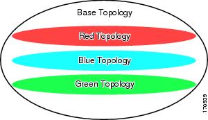
MTR creates a selection of routes within a given device upon which to forward to a given destination. The specific choice of route is based on the class of the packet being forwarded, a class that is an attribute of the packet itself. This design allows packets of different classes to be routed independently from one another. The path that the packet follows is determined by classifiers configured on the devices and interfaces in the network. The figure below shows a base topology, which is a superset of the red, blue, and green topologies.
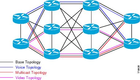
The figure below shows an MTR-enabled network that is configured using the service separation model. The base topology (shown in black) uses NLRI from all reachable devices in the network. The blue, red, and purple paths each represent a different class-specific topology. Each class-specific topology calculates a separate set of paths through the network. Routing and forwarding are independently calculated based on individual sets of NLRI that are carried for each topology.
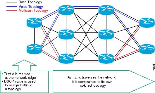
The figure below shows that the traffic is marked at the network edge. As the traffic traverses the network, the marking is used during classification and forwarding to constrain the traffic to its own colored topology.
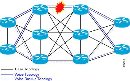
The same topology can have configured backup paths. In the figure below, the preferential path for the voice topology is represented by the solid blue line. In case this path becomes unavailable, you can configure MTR to choose the voice backup path represented by the dotted blue line. Both of these paths represent the same topology and none overlap.
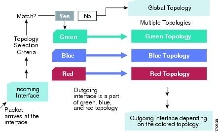
The figure below shows the MTR forwarding model at the system level. When a packet arrives at the incoming interface, the marking is examined. If the packet marking matches a topology, the associated topology is consulted, the next hop for that topology is determined, and the packet is forwarded. If there is no forwarding entry within a topology, the packet is dropped. If the packet does not match any classifier, it is forwarded to the base topology. The outgoing interface is a function of the colored route table in which the lookup is done.
MTR is implemented in Cisco software according to a address family and subaddress family basis. MTR supports up to 32 unicast topologies (including the base topology) and a separate multicast topology. A topology can overlap with another or share any subset of the underlying network. You configure each topology with a unique topology ID. You configure the topology ID under the routing protocol, and the ID is used to identify and group NLRI for each topology in updates for a given protocol.
Unicast Topology Support for MTR
You can configure up to 32 unicast topologies on each device. You first define the topology by entering the global-address-family command in global configuration mode. The address family and optionally the subaddress family are specified in this step. You then enter the topology command in global address family configuration mode. This command places the device in address family topology configuration mode, and the global topology configuration parameters are applied in this mode.
For each new topology that you configure on a device, you increase the total number of routes from the global routing table by the number of routes that are in each new topology [base + topology(n)]. If the device carries a large global routing table, and you plan to add a significant number of routes through the Multitopology Routing (MTR) topology configuration, you can configure the maximum routes command in address family topology configuration mode to limit the number of routes that the device accepts for a given topology and installs into the corresponding Routing Information Base (RIB).
 Note | Per-interface topology configuration parameters override configurations applied in global address family topology configuration mode and router address family topology configuration mode. |
Interface Configuration Support for MTR
The configuration of a Multitopology Routing (MTR) topology in interface configuration mode allows you to enable or disable MTR on a per-interface basis. By default, a class-specific topology does not include any interfaces.
You can include or exclude individual interfaces by configuring the topology interface configuration command. You specify the address family and the topology (base or class-specific) when entering this command. The subaddress family can be specified. If no subaddress family is specified, the unicast subaddress family is used by default.
You can include globally all interfaces on a device in a topology by entering the all-interfaces command in routing topology configuration mode. Per-interface topology configuration applied with the topology command overrides global interface configuration.
The interface configuration support for MTR has these characteristics:
- Per-interface routing configuration: Interior Gateway Protocol (IGP) routing and metric configurations can be applied in interface topology configuration mode. Per-interface metrics and routing behaviors can be configured for each IGP.
- Open Shortest Path First (OSPF) interface topology configuration: Interface mode OSPF configurations for a class-specific topology are applied in interface topology configuration mode. In this mode, you can configure an interface cost or disable OSPF routing without removing the interface from the global topology configuration.
- Enhanced Interior Gateway Routing Protocol (EIGRP) interface topology configuration: Interface mode EIGRP configurations for a class-specific topology are applied in interface topology configuration mode. In this mode, you can configure various EIGRP features.
- Intermediate System-to-Intermediate System (IS-IS) interface topology configuration: Interface mode IS-IS configurations for a class-specific topology are applied in interface topology configuration mode. In this mode, you can configure an interface cost or disable IS-IS routing without removing the interface from the global topology configuration.
MTR Deployment Models
The base topology is the superset of all topologies in the network. It is defined by Network Layer Reachability Information (NLRI) for all reachable devices regardless of the deployment model that is used. Multitopology Routing (MTR) can be deployed using the service separation MTR model, or it can deployed using the overlapping MTR model. Each model represents a different approach to deploying MTR. However, these models are not mutually exclusive. Any level of variation of a combined model can be deployed.
Service Separation MTR Model
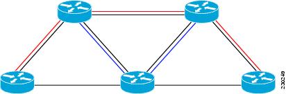
The figure below shows the service separation model where no topologies except for the base topology (shown in black) overlap with each other. In the service separation model, each class of traffic is constrained to its own exclusive topology. This model restricts the given class of traffic to a subset of the network. This model is less configuration intensive than the overlapping MTR model because no topology-specific metrics need to be configured.
Overlapping MTR Model
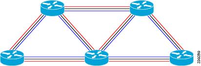
In the overlapping Multitopology Routing (MTR) model, all topologies are configured to run over all devices in the network. This model provides the highest level of redundancy. All classes of traffic can use all links. Per-topology metrics are then configured to bias different classes of traffic to use different parts of the network. The redundancy that this model provides, however, makes it more configuration intensive than the service separation MTR model. In the figure below, all topologies are configured to run over all network devices. In this model, per-topology metrics are configured to bias the preferred routes for each topology.
MTR Deployment Configuration
Multitopology Routing (MTR) supports both full and incremental deployment configurations. To support these options, MTR provides two different, configurable forwarding rules: strict forwarding mode for full deployment and incremental forwarding mode for an incremental deployment.
- Strict Forwarding Mode for Full Deployment of MTR
- Incremental Forwarding Mode for Incremental Deployment of MTR
Strict Forwarding Mode for Full Deployment of MTR
Strict forwarding mode is the default forwarding mode in Multitopology Routing (MTR). In this mode, the device looks for a forwarding route only in the class-specific Forwarding Information Base (FIB). If no forwarding route is found, the device drops the received packet. In this mode, the device performs a longest match lookup for the topology FIB entry. This mode is designed for full deployment, where MTR is enabled on every device in the network or every device in the topology. Strict forwarding mode should be enabled after an incremental deployment transition has been completed or when all devices in the network or topology are MTR enabled. You can enable strict forwarding mode after incremental forwarding mode by entering the no forward-base command in address family topology configuration mode.
Incremental Forwarding Mode for Incremental Deployment of MTR
Incremental forwarding mode is designed to support transitional or incremental deployment of Multitopology Routing (MTR), where devices in the network are not MTR enabled. In this mode, the device looks for a forwarding entry first in the class-specific Forwarding Information Base (FIB). If an entry is not found, the device looks for the longest match in the base topology FIB. If an entry is found in the base topology FIB, the device forwards the packet on the base topology. If a forwarding entry is not found in the base topology FIB, the device drops the packet.
This mode is designed to preserve connectivity during an incremental deployment of MTR and is recommended for use only during migration (the transition from a non-MTR to an MTR-enabled network). Class-specific traffic for a given destination is forwarded over contiguous segments of the class-specific topology containing that destination; otherwise, it is forwarded over the base topology.
This forwarding mode can be enabled to support mixed networks where some devices are not configured to run MTR. You enable incremental forwarding mode by entering the forward-base command in address family topology configuration mode.
Guidelines for Enabling and Disabling MTR
The section provides guidelines and procedures for enabling or disabling Multitopology Routing (MTR) in a production network. These guidelines assume that all participating networking devices are running a software image that supports MTR. The guidelines are designed to prevent major traffic interruptions due to misconfiguration and to minimize temporary transitional effects that can occur when you introduce or remove a topology from a network. The following guidelines must be implemented in the order that they are described:
First, create a class-specific topology on all networking devices and enable incremental forwarding mode by entering the forward-base command in address family topology configuration mode. Configure incremental forwarding whenever a topology is introduced or removed from the network. The topology is defined as a global container at this stage. No routing or forwarding can occur within the topology. Routing protocol support should not be configured.
Second, configure classification rules for the class-specific topology. You must consistently apply classification on all devices in the topology; each device has identical classifier configuration. You activate the topology when you attach a valid classification configuration to the global topology configuration. You can use ping and traceroute commands to verify reachability for interfaces and networking devices that are in the same topology and configured with identical classification.
Third, configure routing protocol support and static routing. Configure the devices in the topology one at a time. This configuration should include an interface, router process, and routing protocol-specific metrics and filters.
Enable routing in the topology by using a physical pattern in a contiguous manner relative to a single starting point. For example, configure all interfaces on a single device, and then all interfaces on each adjacent device. Follow this pattern until the task is complete. The starting point can be on the edge or core of the network. This recommendation is designed to increase the likelihood that class-specific traffic is forwarded on the same paths in the incremental topology as it is on the full topology when MTR is completely deployed.
If your network design requires strict forwarding mode, you should disable incremental forwarding only after you configure routing on all devices in a given topology. At this stage, MTR is fully operational. Class-specific traffic is forwarded only over devices within the topology. Traffic that is not classified or destined for the topology is dropped.
When disabling a topology, reenable incremental forwarding mode. Remove custom route configuration, such as route summarization and default routes before disabling a topology, and reapply custom route configuration only after the topology is reenabled. This recommendation is designed to prevent traffic interruption because some destinations might be obscured during the transition. Custom route configuration is most useful when all of the more-specific routes are available in the routing table of the topology.
How to Configure Multitopology Routing
- Configuring a Unicast Topology for MTR
- Configuring an MTR Topology in Interface Configuration Mode
- Enabling Topology Statistics Accounting for MTR
- Monitoring Interface and Topology IP Traffic Statistics for MTR
- Testing Network Connectivity for MTR
Configuring a Unicast Topology for MTR
DETAILED STEPS
Configuring an MTR Topology in Interface Configuration Mode
Define a topology globally before configuring the per-interface topology configuration.
Note | Interfaces cannot be excluded from the base topology by design. However, an Interior Gateway Protocol (IGP) can be excluded from an interface in a base topology configuration. |
DETAILED STEPS
| Command or Action | Purpose | |
|---|---|---|
Step 1 |
enable
Example: Device> enable |
Enables privileged EXEC mode. |
Step 2 |
configure terminal
Example: Device# configure terminal |
Enters global configuration mode. |
Step 3 |
interface
type number
Example: Device(config)# interface Ethernet 0/0 |
Specifies the interface type and number, and enters interface configuration mode. |
Step 4 |
topology ipv4 [multicast |
unicast] {topology-name [disable] |
base}
Example: Device(config-if)# topology ipv4 VOICE |
Enters interface topology configuration mode to configure a Multitopology Routing (MTR) topology name on an interface.
|
Step 5 |
end
Example: Device(config-if-topology)# end |
Exits interface topology configuration mode and returns to privileged EXEC mode. |
Enabling Topology Statistics Accounting for MTR
DETAILED STEPS
| Command or Action | Purpose | |
|---|---|---|
Step 1 |
enable
Example: Device> enable |
Enables privileged EXEC mode. |
Step 2 |
configure terminal
Example: Device# configure terminal |
Enters global configuration mode. |
Step 3 |
global-address-family ipv4 [multicast |
unicast]
Example: Device(config)# global-address-family ipv4 |
Enters global address family configuration mode. |
Step 4 |
topology accounting
Example: Device(config-af)# topology accounting |
Enables topology accounting on all interfaces in the global address family for all IPv4 unicast topologies in the default virtual routing and forwarding (VRF) instance. |
Step 5 |
exit
Example: Device(config-af)# exit |
Exits global address family configuration mode. |
Step 6 |
interface
type number
Example: Device(config)# interface FastEthernet 1/10 |
Specifies the interface type and number, and enters interface configuration mode. |
Step 7 |
ip topology-accounting
Example: Device(config-if)# ip topology-accounting |
Enables topology accounting for all IPv4 unicast topologies in the VPN VRF associated with the specified interface. |
Step 8 |
end
Example: Device(config-if)# end |
Exits interface configuration mode and returns to privileged EXEC mode. |
Monitoring Interface and Topology IP Traffic Statistics for MTR
Use any of the following commands in any order to monitor interface and topology IP traffic statistics for Multitopology Routing (MTR).
DETAILED STEPS
| Command or Action | Purpose | |
|---|---|---|
Step 1 |
enable
Example: Device> enable |
Enables privileged EXEC mode. |
Step 2 |
show ip interface [type number] [topology {name |
all |
base}] [stats]
Example: Device# show ip interface FastEthernet 1/10 stats |
(Optional) Displays IP traffic statistics for all interfaces or statistics related to the specified interface.
|
Step 3 |
show ip traffic [topology {name |
all |
base}]
Example: Device# show ip traffic topology VOICE |
(Optional) Displays global IP traffic statistics (an aggregation of all the topologies when MTR is enabled) or statistics related to a particular topology. |
Step 4 |
clear ip interface
type number [topology {name |
all |
base}] [stats]
Example: Device# clear ip interface FastEthernet 1/10 topology all |
(Optional) Resets interface-level IP traffic statistics. |
Step 5 |
clear ip traffic [topology {name |
all |
base}]
Example: Device# clear ip traffic topology all |
(Optional) Resets IP traffic statistics. |
Testing Network Connectivity for MTR
DETAILED STEPS
| Command or Action | Purpose | |
|---|---|---|
Step 1 |
enable
Example: Device> enable |
Enables privileged EXEC mode. |
Step 2 |
ping [vrf
vrf-name |
topology
topology-name]
protocol [target-address] [source-address]
Example: Device# ping topology VOICE ip |
Configures the device to transmit ping messages to the target host in a topology. |
Step 3 |
traceroute [vrf
vrf-name |
topology
topology-name] [protocol]
destination
Example: Device# traceroute VOICE |
Configures the device to trace the specified host in a topology.
|
Configuration Examples for Multitopology Routing
- Example: Global Interface Configuration
- Example: Incremental Forwarding Configuration
- Example: Unicast Topology Verification
- Example: MTR Topology in Interface Configuration Mode
- Examples: Monitoring Interface and Topology IP Traffic Statistics for MTR
- Examples: Testing Network Connectivity for MTR
Example: Global Interface Configuration
The following example shows how to create a topology instance named VOICE. This topology is configured to use all operational interfaces on the device. Per the default forwarding rule (strict), only packets destined for routes in the VOICE topology Routing Information Base (RIB) are forwarded. Packets that do not have a topology-specific forwarding entry are dropped.
global-address-family ipv4
 topology VOICE
  all-interfaces
  end
Example: Incremental Forwarding Configuration
The following example shows how to create a topology instance named VIDEO. This topology is configured to accept and install a maximum of 1000 routes in the VIDEO topology Routing Information Base (RIB). Incremental forwarding mode is configured so that the device forwards packets over the base topology if no forwarding entry is found in the class-specific RIB.
global-address-family ipv4
 topology VIDEO
  forward-base
  maximum routes 1000
  end
Example: Unicast Topology Verification
The output of the show topology detail command displays information about class-specific and base topologies. This information includes the address family, associated interfaces, interface and topology status, topology name, and associated virtual routing and forwarding (VRF) instance.
Device# show topology detail

Topology: base
  Address-family: ipv4
  Associated VPN VRF is default
  Topology state is UP
  Associated interfaces:
    Ethernet0/0, operation state: UP
    Ethernet0/1, operation state: DOWN
    Ethernet0/2, operation state: DOWN
    Ethernet0/3, operation state: DOWN
    Loopback0, operation state: UP
Topology: VIDEO
  Address-family: ipv4
  Associated VPN VRF is default
  Topology state is UP
  Topology fallback is enabled
  Topology maximum route limit 1000, warning limit 90% (900)
  Associated interfaces:
Topology: VOICE
  Address-family: ipv4
  Associated VPN VRF is default
  Topology state is UP
  Topology is enabled on all interfaces
  Associated interfaces:
    Ethernet0/0, operation state: UP
    Ethernet0/1, operation state: DOWN
    Ethernet0/2, operation state: DOWN
    Ethernet0/3, operation state: DOWN
    Loopback0, operation state: UP
Topology: base
  Address-family: ipv4 multicast
  Associated VPN VRF is default
  Topology state is DOWN
  Route Replication Enabled:
    from unicast all
  Associated interfaces:
Examples: Monitoring Interface and Topology IP Traffic Statistics for MTR
In the following example, the show ip interface command displays IP traffic statistics for Fast Ethernet interface 1/10:
Device# show ip interface FastEthernet 1/10 stats

FastEthernet1/10
	5 minutes input rate 0 bits/sec, 0 packet/sec,
	5 minutes output rate 0 bits/sec, 0 packet/sec,
	201 packets input, 16038 bytes
	588 packets output, 25976 bytes
In this example, the show ip traffic command displays statistics related to a particular topology:
Device# show ip traffic topology VOICE

  Topology: VOICE
  5 minute input rate 0 bits/sec, 0 packet/sec,
  5 minute output rate 0 bits/sec, 0 packet/sec,
  100 packets input, 6038 bytes,
  88 packets output, 5976 bytes.
Examples: Testing Network Connectivity for MTR
The following example shows how to send a ping to the 10.1.1.2 neighbor in the VOICE topology:
Device# ping topology VOICE ip 10.1.1.2
Type escape sequence to abort.
Sending 5, 100-byte ICMP Echos to 10.1.1.2, timeout is 2 seconds:
!!!!!
Success rate is 100 percent (5/5), round-trip min/avg/max = 1/1/4 ms
The following example shows how to trace the 10.1.1.4 host in the VOICE topology:
Device# traceroute VOICE ip 10.1.1.4
Type escape sequence to abort.
Tracing the route to 10.1.1.4
  1 10.1.1.2 4 msec *  0 msec
  2 10.1.1.3 4 msec *  2 msec
  3 10.1.1.4 4 msec *  4 msec
Additional References
Related Documents
Technical Assistance
|
Description |
Link |
|---|---|
|
The Cisco Support and Documentation website provides online resources to download documentation, software, and tools. Use these resources to install and configure the software and to troubleshoot and resolve technical issues with Cisco products and technologies. Access to most tools on the Cisco Support and Documentation website requires a Cisco.com user ID and password. |
Feature Information for Multitopology Routing
The following table provides release information about the feature or features described in this module. This table lists only the software release that introduced support for a given feature in a given software release train. Unless noted otherwise, subsequent releases of that software release train also support that feature.
Use Cisco Feature Navigator to find information about platform support and Cisco software image support. To access Cisco Feature Navigator, go to www.cisco.com/go/cfn. An account on Cisco.com is not required.
| Table 1 | Feature Information for Multitopology Routing |
|
Feature Name |
Releases |
Feature Information |
|---|---|---|
|
Multitopology Routing |
12.2(33)SRB 15.0(1)S |
Multitopology Routing (MTR) enables you to configure service differentiation through class-based forwarding. MTR provides multiple logical topologies over a single physical network. Service differentiation can be achieved by forwarding different traffic types over different logical topologies that could take different paths to the same destination. MTR can be used, for example, to define separate topologies for voice, video, and data traffic classes. The following commands were introduced or modified: all-interfaces, clear ip interface, clear ip route topology, clear ip traffic, debug topology, exit-global-af, exit-if-topology, exit-topo, forward-base, global-address-family ipv4, ip route topology, ip topology accounting, maximum routes, ping, route replicate, show ip interface, show ip protocols topology, show ip route topology, show ip static route, show ip static route summary, show ip traffic, show topology, shutdown, topology, topology accounting, traceroute. |
Glossary
base topology--The entire network for which the usual set of routes are calculated. This topology is the same as the default global routing table that exists without Multitopology Routing (MTR) being used.
class-specific topology--New topologies that are defined over and above the existing base topology; each class-specific topology is represented by its own Routing Information Base (RIB) and Forwarding Information Base (FIB).
classification--Selection and matching of traffic that needs to be provided with a different treatment based on its mark. Classification is a read-only operation.
DSCP--differentiated services code point. Six bits in the Type of Service (ToS) field. Two bits are used for Explicit Congestion Notification, which are used to mark the packet.
incremental forwarding mode--Incremental forwarding mode is designed to support transitional or incremental deployment of MTR, where devices are in the network that are not MTR enabled. In this mode, the device looks for a forwarding entry first in the class-specific FIB. If an entry is not found, the device then looks for the longest match in the base topology FIB. If an entry is found in the base topology FIB, the packet is forwarded on the base topology. If a forwarding entry is not found in the base topology FIB, the packet is dropped.
marking--Setting a value in the packet or frame. Marking is a read and write operation.
multitopology--Multitopology means that each topology routes and forward a subset of the traffic as defined by the classification criteria.
NLRI--Network Layer Reachability Information.
strict forwarding mode--Strict forwarding mode is the default forwarding mode for MTR. Only routes in the topology-specific routing table are considered. Among these, the longest match for the destination address is used. If no route containing the destination address can be found in the topology specific table, the packet is dropped.
TID--Topology Identifier. Each topology is configured with a unique topology ID. The topology ID is configured under the routing protocol and is used to identify and group NLRI for each topology in updates for a given protocol.
Cisco and the Cisco Logo are trademarks of Cisco Systems, Inc. and/or its affiliates in the U.S. and other countries. A listing of Cisco's trademarks can be found at www.cisco.com/go/trademarks. Third party trademarks mentioned are the property of their respective owners. The use of the word partner does not imply a partnership relationship between Cisco and any other company. (1005R)
Any Internet Protocol (IP) addresses and phone numbers used in this document are not intended to be actual addresses and phone numbers. Any examples, command display output, network topology diagrams, and other figures included in the document are shown for illustrative purposes only. Any use of actual IP addresses or phone numbers in illustrative content is unintentional and coincidental.