
 Feedback
Contents
- BGP Support for MTR
- Finding Feature Information
- Prerequisites for BGP Support for MTR
- Restrictions for BGP Support for MTR
- Information About BGP Support for MTR
- Routing Protocol Support for MTR
- BGP Network Scope
- MTR CLI Hierarchy Under BGP
- BGP Sessions for Class-Specific Topologies
- Topology Translation Using BGP
- Topology Import Using BGP
- How to Configure BGP Support for MTR
- Activating an MTR Topology by Using BGP
- What to Do Next
- Importing Routes from an MTR Topology by Using BGP
- Configuration Examples for BGP Support for MTR
- Example BGP Topology Translation Configuration
- Example BGP Scope Global and VRF Configuration
- Example BGP Topology Verification
- Example Importing Routes from an MTR Topology by Using BGP
- Additional References
- Feature Information for BGP Support for MTR
BGP Support for MTR
The BGP Support for MTR feature provides Border Gateway Protocol (BGP) support for multiple logical topologies over a single physical network. This module describes how to configure BGP for Multitopology Routing (MTR).
Finding Feature Information
Your software release may not support all the features documented in this module. For the latest feature information and caveats, see the release notes for your platform and software release. To find information about the features documented in this module, and to see a list of the releases in which each feature is supported, see the Feature Information Table at the end of this document.
Use Cisco Feature Navigator to find information about platform support and Cisco software image support. To access Cisco Feature Navigator, go to www.cisco.com/go/cfn. An account on Cisco.com is not required.
Restrictions for BGP Support for MTR
- Redistribution within a topology is permitted. Redistribution from one topology to another is not permitted. This restriction is designed to prevent routing loops. You can use topology translation or topology import functionality to move routes from one topology to another.
- Only a single multicast topology can be configured, and only the base topology can be specified if a multicast topology is created.
Information About BGP Support for MTR
Routing Protocol Support for MTR
You must enable IP routing on the router for MTR to operate. MTR supports static and dynamic routing in Cisco IOS software. You can enable dynamic routing per-topology to support inter-domain and intra-domain routing. Route calculation and forwarding are independent for each topology. MTR support is integrated into Cisco IOS software for the following protocols:
- Border Gateway Protocol (BGP)
- Enhanced Interior Gateway Routing Protocol (EIGRP)
- Integrated Intermediate System-to-Intermediate System (IS-IS)
- Open Shortest Path First (OSPF)
You apply the per-topology configuration in router address family configuration mode of the global routing process (router configuration mode). The address family and subaddress family are specified when entering address-family configuration mode. You specify the topology name and topology ID by entering the topology command in address-family configuration mode.
You configure each topology with a unique topology ID under the routing protocol. The topology ID is used to identify and group NLRI for each topology in updates for a given protocol. In OSPF, EIGRP, and IS-IS, you enter the topology ID during the first configuration of the topology command for a class-specific topology. In BGP, you configure the topology ID by entering the bgp tid command under the topology configuration.
You can configure class-specific topologies with different metrics than the base topology. Interface metrics configured on the base topology can be inherited by the class-specific topology. Inheritance occurs if no explicit inheritance metric is configured in the class-specific topology.
You configure BGP support only in router configuration mode. You configure Interior Gateway Protocol (IGP) support in router configuration mode and in interface configuration mode.
By default, interfaces are not included in non-base topologies. For routing protocol support for EIGRP, IS-IS, and OSPF, you must explicitly configure a non-base topology on an interface. You can override the default behavior by using the all-interfaces command in address family topology configuration mode. The all-interfaces command causes the non-base topology to be configured on all interfaces of the router that are part of the default address space or the VRF in which the topology is configured.
BGP Network Scope
To implement MTR for BGP, the scope hierarchy is required, but the scope hierarchy is not limited to MTR use. The scope hierarchy introduces some new configuration modes such as router scope configuration mode. You enter router scope configuration mode by configuring the scope command in router configuration mode. When this command is entered, a collection of routing tables is created.
You configure BGP commands under the scope hierarchy for a single network (globally), or on a per-VRF basis, and are referred to as scoped commands. The scope hierarchy can contain one or more address families.
MTR CLI Hierarchy Under BGP
The BGP CLI provides backward compatibility for pre-MTR BGP configuration and provides a hierarchical implementation of MTR. Router configuration mode is backward compatible with the pre-address family and pre-MTR configuration CLI. Global commands that affect all networks are configured in this configuration mode. For address-family and topology configuration, you configure general session commands and peer templates to be used in the address-family or in the topology configuration mode.
After configuring any global commands, you define the scope either globally or for a specific VRF. You enter address family configuration mode by configuring the address-family command in router scope configuration mode or in router configuration mode. Unicast is the default address family if no subaddress family (SAFI) is specified. MTR supports only the IPv4 address family with a SAFI of unicast or multicast.
Entering address family configuration mode from router configuration mode configures BGP to use pre-MTR-based CLI. This configuration mode is backward compatible with pre-existing address family configurations. Entering address family configuration mode from router scope configuration mode configures the router to use the hierarchical CLI that supports MTR. Address family configuration parameters that are not specific to a topology are entered in this address family configuration mode.
You enter BGP topology configuration mode by configuring the topology (BGP) command in address family configuration mode. You can configure up to 32 topologies (including the base topology) on a router. You configure the topology ID by entering the bgp tid command. All address family and subaddress family configuration parameters for the topology are configured here.
 Note | Configuring a scope for a BGP routing process removes CLI support for pre-MTR-based configuration. |
The following example shows the hierarchy levels that are used when configuring BGP for MTR implementation:
router bgp <autonomous-system-number>
 ! Global commands

 scope {global | vrf <vrf-name>}
  ! Scoped commands

  address-family {<afi>} [<safi>]
   ! Address family specific commands

   topology {<topology-name> | base}
    ! topology specific commands
For detailed steps, see the Activating an MTR Topology by Using BGP section.
BGP Sessions for Class-Specific Topologies
MTR is configured under BGP on a per-session basis. The base unicast and multicast topologies are carried in the global (default) session. A separate session is created for each class-specific topology that is configured under a BGP routing process. Each session is identified by its topology ID. BGP performs a best-path calculation individually for each class-specific topology. A separate RIB and FIB are maintained for each session.
Topology Translation Using BGP
Depending on the design and policy requirements for your network, you might need to install routes from a class-specific topology on one router in a class-specific topology on a neighboring router. Topology translation functionality using BGP provides support for this operation. Topology translation is BGP neighbor-session based. You configure the neighbor translate-topology command by using the IP address and topology ID from the neighbor.
The topology ID identifies the class-specific topology of the neighbor. The routes in the class-specific topology of the neighbor are installed in the local class-specific RIB. BGP performs a best-path calculation on all installed routes and installs these routes into the local class-specific RIB. If a duplicate route is translated, BGP selects and installs only one instance of the route per standard BGP best-path calculation behavior.
Topology Import Using BGP
Topology import functionality using BGP is similar to topology translation. The difference is that routes are moved between class-specific topologies on the same router by using BGP. You configure this function by entering the import topology command and specify the name of the class-specific topology or base topology. Best-path calculations are run on the imported routes before they are installed into the topology RIB. This command also includes a route-map keyword to allow you to filter routes that are moved between class-specific topologies.
For detailed steps, see the Importing Routes from an MTR Topology by Using BGP section.
How to Configure BGP Support for MTR
Activating an MTR Topology by Using BGP
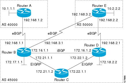
Perform this task to activate an MTR topology inside an address family by using BGP. This task is configured on Router B in the figure below and must also be configured on Router D and Router E. In this task, a scope hierarchy is configured to apply globally, and a neighbor is configured under router scope configuration mode. Under the IPv4 unicast address family, an MTR topology that applies to video traffic is activated for the specified neighbor. There is no interface configuration mode for BGP topologies.
- Be familiar with all the concepts in the Information About BGP Support for MTR section on page 2.
- Configure and activate a global MTR topology configuration.
DETAILED STEPS
What to Do Next
Repeat this task for every topology that you want to enable, and repeat this configuration on all neighbor routers that are to use the topologies.
If you want to import routes from one MTR topology to another on the same router, proceed to the Importing Routes from an MTR Topology by Using BGP section.
Importing Routes from an MTR Topology by Using BGP
Note | Perform this task to import routes from one MTR topology to another on the same router, when multiple topologies are configured on the same router. In this task, a prefix list is defined to permit prefixes from the 10.2.2.0 network, and this prefix list is used with a route map to filter routes moved from the imported topology. A global scope is configured, address family IPv4 is entered, the VIDEO topology is specified, the VOICE topology is imported, and the routes are filtered using the route map named 10NET. |
Note |
|
DETAILED STEPS
| Command or Action | Purpose | |
|---|---|---|
Step 1 |
enable
Example: Router> enable |
Enables privileged EXEC mode. |
Step 2 |
configure terminal
Example: Router# configure terminal |
Enters global configuration mode. |
Step 3 |
ip prefix-list
list-name [seq
seq-value] {deny
network
/
length |
permit
network
/
length} [ge
ge-value] [le
le-value]
Example: Router(config)# ip prefix-list TEN permit 10.2.2.0/24 |
Configures an IP prefix list. |
Step 4 |
route-map
map-name [permit |
deny] [sequence-number]
Example: Router(config)# route-map 10NET |
Creates a route map and enters route map configuration mode. |
Step 5 |
match ip address {access-list-number [access-list-number ... |
access-list-name...] |
access-list-name [access-list-number ...|
access-list-name ] |
prefix-list
prefix-list-name [prefix-list-name...]}
Example: Router(config-route-map)# match ip address prefix-list TEN |
Configures the route map to match a prefix that is permitted by a standard access list, an extended access list, or a prefix list. |
Step 6 |
exit
Example: Router(config-route-map)# exit |
Exits route map configuration mode and returns to global configuration mode. |
Step 7 |
router bgp
autonomous-system-number
Example: Router(config)# router bgp 50000 |
Enters router configuration mode to create or configure a BGP routing process. |
Step 8 |
scope {global |
vrf
vrf-name}
Example: Router(config-router)# scope global |
Defines the scope to the BGP routing process and enters router scope configuration mode.
|
Step 9 |
address-family ipv4 [mdt |
multicast |
unicast]
Example: Router(config-router-scope)# address-family ipv4 |
Enters router scope address family configuration mode to configure an address family session under BGP. |
Step 10 |
topology {base |
topology-name}
Example: Router(config-router-scope-af)# topology VIDEO |
Configures the topology instance in which BGP routes class-specific or base topology traffic, and enters router scope address family topology configuration mode. |
Step 11 |
import topology {base |
topology-name} [route-map
map-name]
Example: Router(config-router-scope-af-topo)# import topology VOICE route-map 10NET |
(Optional) Configures BGP to move routes from one topology to another on the same router. |
Step 12 |
end
Example: Router(config-router-scope-af-topo)# end |
(Optional) Exits router scope address family topology configuration mode and returns to privileged EXEC mode. |
Configuration Examples for BGP Support for MTR
Example BGP Topology Translation Configuration
The following example shows how to configure BGP in the VIDEO topology and how to configure topology translation with the 192.168.2.2 neighbor:
router bgp 45000
 scope global
  neighbor 172.16.1.1 remote-as 50000
  neighbor 192.168.2.2 remote-as 55000
  neighbor 172.16.1.1 transport multi-session
  neighbor 192.168.2.2 transport multi-session
   address-family ipv4
    topology VIDEO
     bgp tid 100
     neighbor 172.16.1.1 activate
     neighbor 192.168.2.2 activate
     neighbor 192.168.2.2 translate-topology 200
     end
clear ip bgp topology VIDEO 50000
Example BGP Scope Global and VRF Configuration
The following example shows how to configure a global scope for a unicast topology and also for a multicast topology. After exiting the router scope configuration mode, a scope is configured for the VRF named DATA.
router bgp 45000
 scope global
  bgp default ipv4-unicast
  neighbor 172.16.1.2 remote-as 45000
  neighbor 192.168.3.2 remote-as 50000
  address-family ipv4 unicast
   topology VOICE
   bgp tid 100
   neighbor 172.16.1.2 activate
   exit
  address-family ipv4 multicast
   topology base
    neighbor 192.168.3.2 activate
    exit
   exit
  exit
 scope vrf DATA
  neighbor 192.168.1.2 remote-as 40000
  address-family ipv4
   neighbor 192.168.1.2 activate
   end
Example BGP Topology Verification
The following example shows summary output for the show ip bgp topology command. Information is displayed about BGP neighbors configured to use the MTR topology named VIDEO.
Router# show ip bgp topology VIDEO summary
BGP router identifier 192.168.3.1, local AS number 45000
BGP table version is 1, main routing table version 1
Neighbor        V    AS MsgRcvd MsgSent   TblVer  InQ OutQ Up/Down  State/PfxRcd
172.16.1.2      4 45000     289     289        1    0    0 04:48:44        0
192.168.3.2     4 50000       3       3        1    0    0 00:00:27        0
The following partial output displays BGP neighbor information under the VIDEO topology:
Router# show ip bgp topology VIDEO neighbors 172.16.1.2
BGP neighbor is 172.16.1.2,  remote AS 45000, internal link
  BGP version 4, remote router ID 192.168.2.1
  BGP state = Established, up for 04:56:30
  Last read 00:00:23, last write 00:00:21, hold time is 180, keepalive interval is 60
seconds
  Neighbor sessions:
    1 active, is multisession capable
  Neighbor capabilities:
    Route refresh: advertised and received(new)
  Message statistics, state Established:
    InQ depth is 0
    OutQ depth is 0
                         Sent       Rcvd
    Opens:                  1          1
    Notifications:          0          0
    Updates:                0          0
    Keepalives:           296        296
    Route Refresh:          0          0
    Total:                297        297
  Default minimum time between advertisement runs is 0 seconds
 For address family: IPv4 Unicast topology VIDEO
  Session: 172.16.1.2 session 1
  BGP table version 1, neighbor version 1/0
  Output queue size : 0
  Index 1, Offset 0, Mask 0x2
1 update-group member
  Topology identifier: 100
.
.
.
  Address tracking is enabled, the RIB does have a route to 172.16.1.2
  Address tracking requires at least a /24 route to the peer
  Connections established 1; dropped 0
  Last reset never
  Transport(tcp) path-mtu-discovery is enabled
Connection state is ESTAB, I/O status: 1, unread input bytes: 0
Minimum incoming TTL 0, Outgoing TTL 255
Local host: 172.16.1.1, Local port: 11113
Foreign host: 172.16.1.2, Foreign port: 179
.
.
.
Example Importing Routes from an MTR Topology by Using BGP
The following example shows how to configure an access list to be used by a route map named BLUE to filter routes imported from the MTR topology named VOICE. Only routes with the prefix 192.168.1.0 are imported.
access-list 1 permit 192.168.1.0 0.0.0.255
route-map BLUE
 match ip address 1
 exit
router bgp 50000
 scope global
  neighbor 10.1.1.2 remote-as 50000
  neighbor 172.16.1.1 remote-as 60000
   address-family ipv4
    topology VIDEO
     bgp tid 100
     neighbor 10.1.1.2 activate
     neighbor 172.16.1.1 activate
     import topology VOICE route-map BLUE
     end
clear ip bgp topology VIDEO 50000
Additional References
Related Documents
Technical Assistance
| Description | Link |
|---|---|
|
The Cisco Support and Documentation website provides online resources to download documentation, software, and tools. Use these resources to install and configure the software and to troubleshoot and resolve technical issues with Cisco products and technologies. Access to most tools on the Cisco Support and Documentation website requires a Cisco.com user ID and password. |
Feature Information for BGP Support for MTR
The following table provides release information about the feature or features described in this module. This table lists only the software release that introduced support for a given feature in a given software release train. Unless noted otherwise, subsequent releases of that software release train also support that feature.
Use Cisco Feature Navigator to find information about platform support and Cisco software image support. To access Cisco Feature Navigator, go to www.cisco.com/go/cfn. An account on Cisco.com is not required.
| Table 1 | Feature Information for BGP Support for MTR |
| Feature Name | Releases | Feature Information |
|---|---|---|
|
BGP Support for MTR |
12.2(33)SRB 15.0(1)S |
This feature provides Border Gateway Protocol (BGP) support for multiple logical topologies over a single physical network. The following commands were introduced or modified: address-family ipv4, bgp tid, clear ip bgp topology, import topology, neighbor translate-topology, neighbor transport, show ip bgp topology, scope, topology. |
Cisco and the Cisco Logo are trademarks of Cisco Systems, Inc. and/or its affiliates in the U.S. and other countries. A listing of Cisco's trademarks can be found at www.cisco.com/go/trademarks. Third party trademarks mentioned are the property of their respective owners. The use of the word partner does not imply a partnership relationship between Cisco and any other company. (1005R)
Any Internet Protocol (IP) addresses and phone numbers used in this document are not intended to be actual addresses and phone numbers. Any examples, command display output, network topology diagrams, and other figures included in the document are shown for illustrative purposes only. Any use of actual IP addresses or phone numbers in illustrative content is unintentional and coincidental.