
 Feedback
Contents
- MPLS VPN Half-Duplex VRF
- Finding Feature Information
- Prerequisites for Configuring MPLS VPN Half-Duplex VRF
- Restrictions for MPLS VPN Half-Duplex VRF
- Information About Configuring MPLS VPN Half-Duplex VRF
- MPLS VPN Half-Duplex VRF Overview
- Upstream and Downstream VRFs
- Reverse Path Forwarding Check
- How to Configure MPLS VPN Half-Duplex VRF
- Configuring the Upstream and Downstream VRFs on the Spoke PE Router
- Associating a VRF with an Interface
- Configuring the Downstream VRF for an AAA Server
- Verifying MPLS VPN Half-Duplex VRF Configuration
- Configuration Examples for MPLS VPN Half-Duplex VRF
- Example Configuring the Upstream and Downstream VRFs on the Spoke PE Router
- Example Associating a VRF with an Interface
- Example Configuring MPLS VPN Half-Duplex VRF Using Static CE-PE Routing
- Example Configuring MPLS VPN Half-Duplex VRF Using RADIUS Server and Static CE-PE Routing
- Example Configuring MPLS VPN Half-Duplex VRF Using Dynamic CE-PE Routing
- Additional References
- Feature Information for MPLS VPN Half-Duplex VRF
MPLS VPN Half-Duplex VRF
The MPLS VPN Half-Duplex VRF feature provides scalable hub-and-spoke connectivity for subscribers of an Multiprotocol Label Switching (MPLS) Virtual Private Network (VPN) service. This feature addresses the limitations of hub-and-spoke topologies by removing the requirement of one virtual routing and forwarding (VRF) instance per spoke. This feature also ensures that subscriber traffic always traverses the central link between the wholesale service provider and the Internet service provider (ISP), whether the subscriber traffic is being routed to a remote network by way of the upstream ISP or to another locally or remotely connected subscriber.
- Finding Feature Information
- Prerequisites for Configuring MPLS VPN Half-Duplex VRF
- Restrictions for MPLS VPN Half-Duplex VRF
- Information About Configuring MPLS VPN Half-Duplex VRF
- How to Configure MPLS VPN Half-Duplex VRF
- Configuration Examples for MPLS VPN Half-Duplex VRF
- Additional References
- Feature Information for MPLS VPN Half-Duplex VRF
Finding Feature Information
Your software release may not support all the features documented in this module. For the latest feature information and caveats, see the release notes for your platform and software release. To find information about the features documented in this module, and to see a list of the releases in which each feature is supported, see the Feature Information Table at the end of this document.
Use Cisco Feature Navigator to find information about platform support and Cisco software image support. To access Cisco Feature Navigator, go to www.cisco.com/go/cfn. An account on Cisco.com is not required.
Restrictions for MPLS VPN Half-Duplex VRF
The following features are not supported on interfaces configured with the MPLS VPN Half-Duplex VRF feature:
- Multicast
- MPLS VPN Carrier Supporting Carrier
- MPLS VPN Interautonomous Systems
Information About Configuring MPLS VPN Half-Duplex VRF
MPLS VPN Half-Duplex VRF Overview
The MPLS VPN Half-Duplex VRF feature provides:
- The MPLS VPN Half-Duplex VRF feature prevents local connectivity between subscribers at the spoke provider edge (PE) router and ensures that a hub site provides subscriber connectivity. Any sites that connect to the same PE router must forward intersite traffic using the hub site. This ensures that the routing done at the spoke site moves from the access-side interface to the network-side interface or from the network-side interface to the access-side interface, but never from the access-side interface to the access-side interface.
- The MPLS VPN Half-Duplex VRF feature prevents situations where the PE router locally switches the spokes without passing the traffic through the upstream ISP. This prevents subscribers from directly connecting to each other, which causes the wholesale service provider to lose revenue.
- The MPLS VPN Half-Duplex VRF feature improves scalability by removing the requirement of one VRF per spoke. If the feature is not configured, when spokes are connected to the same PE router each spoke is configured in a separate VRF to ensure that the traffic between the spokes traverses the central link between the wholesale service provider and the ISP. However, this configuration is not scalable. When many spokes are connected to the same PE router, configuration of VRFs for each spoke becomes quite complex and greatly increases memory usage. This is especially true in large-scale wholesale service provider environments that support high-density remote access to Layer 3 VPNs.
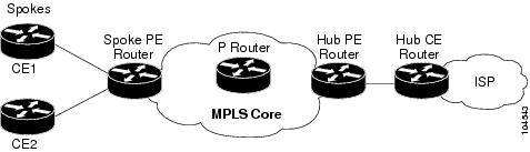
The figure below shows a sample hub-and-spoke topology.
Upstream and Downstream VRFs
The MPLS VPN Half-Duplex VRF feature uses two unidirectional VRFs to forward IP traffic between the spokes and the hub PE router:
- The upstream VRF forwards IP traffic from the spokes toward the hub PE router. This VRF typically contains only a default route but might also contain summary routes and several default routes. The default route points to the interface on the hub PE router that connects to the upstream ISP. The router dynamically learns about the default route from the routing updates that the hub PE router or home gateway sends.
-
The downstream VRF forwards traffic from the hub PE router back to the spokes. This VRF can contain:
- PPP peer routes for the spokes and per-user static routes received from the authentication, authorization, and accounting (AAA) server or from the Dynamic Host Control Protocol (DHCP) server
- Routes imported from the hub PE router
- Border Gateway Protocol (BGP), Open Shortest Path First (OSPF), Routing Information Protocol (RIP), or Enhanced Interior Gateway Routing Protocol (EIGRP) dynamic routes for the spokes
The spoke PE router redistributes routes from the downstream VRF into Multiprotocol Border Gateway Protocol (MP-BGP). That router typically advertises a summary route across the MPLS core for the connected spokes. The VRF configured on the hub PE router imports the advertised summary route.
Reverse Path Forwarding Check
The Reverse Path Forwarding (RPF) check ensures that an IP packet that enters a router uses the correct inbound interface. The MPLS VPN Half-Duplex VRF feature supports unicast RPF check on the spoke-side interfaces. Because different VRFs are used for downstream and upstream forwarding, the RPF mechanism ensures that source address checks occur in the downstream VRF.
Unicast RPF is not on by default. You need to enable it, as described in Configuring Unicast Reverse Path Forwarding .
How to Configure MPLS VPN Half-Duplex VRF
- Configuring the Upstream and Downstream VRFs on the Spoke PE Router
- Associating a VRF with an Interface
- Configuring the Downstream VRF for an AAA Server
- Verifying MPLS VPN Half-Duplex VRF Configuration
Configuring the Upstream and Downstream VRFs on the Spoke PE Router
DETAILED STEPS
Associating a VRF with an Interface
DETAILED STEPS
| Command or Action | Purpose | |
|---|---|---|
Step 1 |
enable
Example: Router> enable |
Enables privileged EXEC mode. |
Step 2 |
configure terminal
Example: Router# configure terminal |
Enters global configuration mode. |
Step 3 |
interface
type
number
Example: Router(config)# interface Ethernet 0/1 |
Configures an interface type and enters interface configuration mode. |
Step 4 |
vrf forwarding
vrf-name [downstream
vrf-name2
Example: Router(config-if)# vrf forwarding vrf1 |
Associates a VRF with an interface or subinterface. |
Step 5 |
ip address
ip-address
mask [secondary]
Example: Router(config-if)# ip address 10.24.24.24 255.255.255.255 |
Sets a primary or secondary IP address for an interface. |
Step 6 |
end
Example: Router(config-if) end |
Exits to privileged EXEC mode. |
Configuring the Downstream VRF for an AAA Server
To configure the downstream VRF for an AAA (RADIUS) server in broadband or remote access situations, enter the following Cisco attribute value:
lcp:interface-config=ip vrf forwarding U downstream D
In standard VPN situations, enter instead the following Cisco attribute value:
ip:vrf-id=U downstream D
Verifying MPLS VPN Half-Duplex VRF Configuration
DETAILED STEPS
| Step 1 |
show vrf [brief |
detail |
id |
interfaces |
lock |
select] [vrf-name]
Use this command to display information about all of the VRFs configured on the router, including the downstream VRF for each associated interface or VAI: Example:
Router# show vrf
Name     Default RD     Interfaces
Down     100:1          POS3/0/3 [D]
                        POS3/0/1 [D]
         100:3          Loopback2
                        Virtual-Access3 [D]
                        Virtual-Access4 [D]
Up       100:2          POS3/0/3
                        POS3/0/1
         100:4          Virtual-Access3
show vrf detail vrf-name Use this command to display detailed information about the VRF you specify, including all interfaces, subinterfaces, and VAIs associated with the VRF. If you do not specify a value for the vrf-name argument, detailed information about all of the VRFs configured on the router appears. The following example shows how to display detailed information for the VRF called vrf1, in a broadband or remote access case: Example:
Router# show vrf detail vrf1
VRF D; default RD 2:0; default VPNID <not set>
  Interfaces:
         Loopback2           Virtual-Access3 [D]  Virtual-Access4 [D]
  Connected addresses are not in global routing table
  Export VPN route-target communities
    RT:2:0
  Import VPN route-target communities
    RT:2:1
  No import route-map
  No export route-map
VRF U; default RD 2:1; default VPNID <not set>
  Interfaces:
    Virtual-Access3          Virtual-Access4
  Connected addresses are not in global routing table
  No Export VPN route-target communities
  Import VPN route-target communities
    RT:2:1
  No import route-map
  No export route-map
The following example shows the VRF detail in a standard VPN situation: Example:
Router# show vrf detail
VRF Down; default RD 100:1; default VPNID <not set> VRF Table ID = 1
  Description: import only from hub-pe
  Interfaces:
    Pos3/0/3 [D]        Pos3/0/1:0.1 [D]
  Connected addresses are not in global routing table
  Export VPN route-target communities
    RT:100:0
  Import VPN route-target communities
    RT:100:1
  No import route-map
  No export route-map
  VRF label distribution protocol: not configured
	VRF Up; default RD 100:2; default VPNID <not set> VRF Table ID = 2
  Interfaces:
    Pos3/0/1            Pos3/0/3
  Connected addresses are not in global routing table
  No Export VPN route-target communities
  Import VPN route-target communities
    RT:100:1
  No import route-map
  No export route-map
  VRF label distribution protocol: not configured
|
| Step 2 |
show ip route vrf
vrf-name
Use this command to display the IP routing table for the VRF you specify, and information about the per-user routes installed in the downstream VRF. The following example shows how to display the routing table for the downstream VRF named D, in a broadband or remote access situation: Example:
Router# show ip route vrf D

Routing Table: D
Codes: C - connected, S - static, R - RIP, M - mobile, B - BGP
       D - EIGRP, EX - EIGRP external, O - OSPF, IA - OSPF inter area
       N1 - OSPF NSSA external type 1, N2 - OSPF NSSA external type 2
       E1 - OSPF external type 1, E2 - OSPF external type 2
       i - IS-IS, L1 - IS-IS level-1, L2 - IS-IS level-2, ia - IS-IS interarea
       * - candidate default, U - per-user static route, o - ODR
       P - periodic downloaded static route
Gateway of last resort is not set
	10.0.0.0/8 is variably subnetted, 5 subnets, 2 masks
U 		10.0.0.2/32 [1/0] via 10.0.0.1
S 		10.0.0.0/8 is directly connected, Null0
U 		10.0.0.5/32 [1/0] via 10.0.0.2
C 		10.8.1.2/32 is directly connected, Virtual-Access4
C 		10.8.1.1/32 is directly connected, Virtual-Access3
The following example shows how to display the routing table for the downstream VRF named Down, in a standard VPN situation: Example:
Router# show ip route vrf Down

Routing Table: Down
Codes: C - connected, S - static, R - RIP, M - mobile, B - BGP
       D - EIGRP, EX - EIGRP external, O - OSPF, IA - OSPF inter area
       N1 - OSPF NSSA external type 1, N2 - OSPF NSSA external type 2
       E1 - OSPF external type 1, E2 - OSPF external type 2
       i - IS-IS, su - IS-IS summary, L1 - IS-IS level-1, L2 - IS-IS level-2
       ia - IS-IS inter area, * - candidate default, U - per-user static route
       o - ODR, P - periodic downloaded static route
Gateway of last resort is 10.13.13.13 to network 0.0.0.0
C 	10.2.0.0/8 is directly connected, Pos3/0/3
     10.3.0.0/32 is subnetted, 1 subnets
B       10.4.16.16 [200/0] via 10.13.13.13, 1w3d
B 	10.6.0.0/8 [200/0] via 10.13.13.13, 1w3d
C 	10.0.0.0/8 is directly connected, Pos3/0/1
	10.7.0.0/16 is subnetted, 1 subnets
B 		10.7.0.0 [20/0] via 10.0.0.2, 1w3d
     10.0.6.0/32 is subnetted, 1 subnets
B       10.0.6.14 [20/0] via 10.0.0.2, 1w3d
     10.8.0.0/32 is subnetted, 1 subnets
B       10.8.15.15 [20/0] via 10.0.0.2, 1w3d
B*   0.0.0.0/0 [200/0] via 10.0.0.13, 1w3d
The following example shows how to display the routing table for the upstream VRF named U in a broadband or remote access situation: Example:
Router# show ip route vrf U
Routing Table: U
Codes: C - connected, S - static, R - RIP, M - mobile, B - BGP
       D - EIGRP, EX - EIGRP external, O - OSPF, IA - OSPF inter area
       N1 - OSPF NSSA external type 1, N2 - OSPF NSSA external type 2
       E1 - OSPF external type 1, E2 - OSPF external type 2
       i - IS-IS, L1 - IS-IS level-1, L2 - IS-IS level-2, ia - IS-IS interarea
       * - candidate default, U - per-user static route, o - ODR
       P - periodic downloaded static route
Gateway of last resort is 192.168.0.20 to network 0.0.0.0
	10.0.0.0/32 is subnetted, 1 subnets
C 		10.0.0.8 is directly connected, Loopback2
B*   0.0.0.0/0 [200/0] via 192.168.0.20, 1w5d
The following example shows how to display the routing table for the upstream VRF named Up in a standard VPN situation: Example:
Router# show ip route vrf Up
Routing Table: Up
Codes: C - connected, S - static, R - RIP, M - mobile, B - BGP
       D - EIGRP, EX - EIGRP external, O - OSPF, IA - OSPF inter area
       N1 - OSPF NSSA external type 1, N2 - OSPF NSSA external type 2
       E1 - OSPF external type 1, E2 - OSPF external type 2
       i - IS-IS, su - IS-IS summary, L1 - IS-IS level-1, L2 - IS-IS level-2
       ia - IS-IS inter area, * - candidate default, U - per-user static route
       o - ODR, P - periodic downloaded static route
Gateway of last resort is 10.13.13.13 to network 0.0.0.0
	10.2.0.0/32 is subnetted, 1 subnets
C 		10.2.0.1 is directly connected, Pos3/0/3
     10.3.0.0/32 is subnetted, 1 subnets
B       10.3.16.16 [200/0] via 10.13.13.13, 1w3d
B 	10.6.0.0/8 [200/0] via 10.13.13.13, 1w3d
	10.0.0.0/32 is subnetted, 1 subnets
C 		10.0.0.1 is directly connected, Pos3/0/1
B*   0.0.0.0/0 [200/0] via 10.13.13.13, 1w3d
|
| Step 3 |
show running-config [interface
type
number]
Use this command to display information about the interfaceyou specify, including information about the associated upstream and downstream VRFs. The following example shows how to display information about the subinterface named POS3/0/1: Example:
Router# show running-config interface POS3/0/1
Building configuration...
Current configuration : 4261 bytes
!
interface POS3/0/1
ip vrf forwarding Up downstream Down
ip address 10.0.0.1 255.0.0.0
end
|
Configuration Examples for MPLS VPN Half-Duplex VRF
- Example Configuring the Upstream and Downstream VRFs on the Spoke PE Router
- Example Associating a VRF with an Interface
- Example Configuring MPLS VPN Half-Duplex VRF Using Static CE-PE Routing
- Example Configuring MPLS VPN Half-Duplex VRF Using RADIUS Server and Static CE-PE Routing
- Example Configuring MPLS VPN Half-Duplex VRF Using Dynamic CE-PE Routing
Example Configuring the Upstream and Downstream VRFs on the Spoke PE Router
The following example configures an upstream VRF named Up:
Router> enable
Router# configure terminal
Router(config)# vrf definition Up
Router(config-vrf)# rd 1:0
Router(config-vrf)# address-family ipv4
Router(config-vrf-af)# route-target import 1:0
Router(config-vrf-af)# exit-address-family
The following example configures a downstream VRF named Down:
Router> enable
Router# configure terminal
Router(config)# vrf definition Down
Router(config-vrf)# rd 1:8
Router(config-vrf)# address-family ipv4
Router(config-vrf-af)# route-target import 1:8
Router(config-vrf-af)# exit-address-family
Example Associating a VRF with an Interface
The following example associates the VRF named Up with POS 3/0/1 subinterface and specifies the downstream VRF named Down:
Router> enable
Router# configure terminal
Router(config)# interface POS 3/0/1
Router(config-if)# vrf forwarding Up downstream Down
Router(config-if)# ip address 10.0.0.1 255.0.0.0
Example Configuring MPLS VPN Half-Duplex VRF Using Static CE-PE Routing
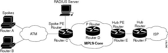
This example uses the hub-and-spoke topology shown in the figure below with local authentication (that is, the RADIUS server is not used):
vrf definition D
 rd 1:8
 address-family ipv4
 route-target export 1:100
 exit-address-family
!
vrf definition U
 rd 1:0
 address-family ipv4
 route-target import 1:0
 exit-address-family
!
ip cef
vpdn enable
!
vpdn-group U
 accept-dialin
  protocol pppoe
  virtual-template 1
!
interface Loopback 2
 vrf forwarding U
 ip address 10.0.0.8 255.255.255.255
!
interface ATM 2/0
 description Mze ATM3/1/2
 no ip address
 no atm ilmi-keepalive
 pvc 0/16 ilmi
!
 pvc 3/100
  protocol pppoe
!
pvc 3/101
  protocol pppoe
!
Example Configuring MPLS VPN Half-Duplex VRF Using RADIUS Server and Static CE-PE Routing
The following example shows how to connect two Point-to-Point Protocol over Ethernet (PPPoE) clients to a single VRF pair on the spoke PE router named Router C. Although both PPPoE clients are configured in the same VRF, all communication occurs using the hub PE router. Half-duplex VRFs are configured on the spoke PE. The client configuration is downloaded to the spoke PE from the RADIUS server.
This example uses the hub-and-spoke topology shown in the figure above.
 Note | The wholesale provider can forward the user authentication request to the corresponding ISP. If the ISP authenticates the user, the wholesale provider appends the VRF information to the request that goes back to the PE router. |
aaa new-model
!
aaa group server radius R
 server 10.0.20.26 auth-port 1812 acct-port 1813
!
aaa authentication ppp default group radius
aaa authorization network default group radius
!
vrf defintion D
 description Downstream VRF - to spokes
 rd 1:8
 address-family ipv4
 route-target export 1:100
 exit-address-family
!
vrf definition U
 description Upstream VRF - to hub
 rd 1:0
 address-family ipv4
 route-target import 1:0
 exit-address-family
!
ip cef
vpdn enable
!
vpdn-group U
 accept-dialin
  protocol pppoe
  virtual-template 1
!
interface Loopback2
 vrf forwarding U
 ip address 10.0.0.8 255.255.255.255
!
interface ATM2/0
  pvc 3/100
  protocol pppoe
 !
pvc 3/101
  protocol pppoe
 !
interface virtual-template 1
 no ip address
 ppp authentication chap
!
router bgp 1
 no synchronization
 neighbor 172.16.0.34 remote-as 1
 neighbor 172.16.0.34 update-source Loopback0
 no auto-summary
 !
address-family vpnv4
  neighbor 172.16.0.34 activate
  neighbor 172.16.0.34 send-community extended
  auto-summary
  exit-address-family
 !
address-family ipv4 vrf U
  no auto-summary
  no synchronization
  exit-address-family
!
address-family ipv4 vrf D
  redistribute static
  no auto-summary
  no synchronization
  exit-address-family
!
ip local pool U-pool 10.8.1.1 2.8.1.100
ip route vrf D 10.0.0.0 255.0.0.0 Null0
!
radius-server host 10.0.20.26 auth-port 1812 acct-port 1813
radius-server key cisco
Example Configuring MPLS VPN Half-Duplex VRF Using Dynamic CE-PE Routing
The following example shows how to use OSPF to dynamically advertise the routes on the spoke sites.
This example uses the hub-and-spoke topology shown in the figure above.
Creating the VRFs
vrf definition Down
rd 100:1
address-family ipv4
route-target export 100:0
exit-address-family
!
vrf definition Up
rd 100:2
address-family ipv4
route-target import 100:1
exit-address-family
Configuring BGP Toward Core
router bgp 100
 no bgp default ipv4-unicast
 bgp log-neighbor-changes
 bgp graceful-restart restart-time 120
 bgp graceful-restart stalepath-time 360
 bgp graceful-restart
 neighbor 10.13.13.13 remote-as 100
 neighbor 10.13.13.13 update-source Loopback0
 !
 address-family vpnv4
 neighbor 10.13.13.13 activate
 neighbor 10.13.13.13 send-community extended
 bgp scan-time import 5
 exit-address-family
Configuring BGP Toward Edge
address-family ipv4 vrf Up
no auto-summary
no synchronization
exit-address-family
!
address-family ipv4 vrf Down
redistribute ospf 1000 vrf Down
no auto-summary
no synchronization
exit-address-family
Spoke PE's Core-Facing Interfaces and Processes
interface Loopback 0
 ip address 10.11.11.11 255.255.255.255
!
interface POS 3/0/2
 ip address 10.0.1.1 255.0.0.0
 mpls label protocol ldp
 mpls ip
!
router ospf 100
 log-adjacency-changes
 auto-cost reference-bandwidth 1000
 nsf enforce global
 redistribute connected subnets
 network 10.11.11.11 0.0.0.0 area 100
 network 10.0.1.0 0.255.255.255 area 100
Spoke PE's Edge-Facing Interfaces and Processes
interface Loopback 100
vrf forwarding Down
 ip address 10.22.22.22 255.255.255.255
!
interface POS 3/0/1
vrf forwarding Up downstream Down
 ip address 10.0.0.1 255.0.0.0
!
interface POS 3/0/3
vrf forwarding Up downstream Down
 ip address 10.2.0.1 255.0.0.0
!
router ospf 1000 vrf Down
 router-id 10.22.22.22
 log-adjacency-changes
 auto-cost reference-bandwidth 1000
 nsf enforce global
 redistribute connected subnets
 redistribute bgp 100 metric-type 1 subnets
 network 10.22.22.22 0.0.0.0 area 300
 network 10.0.0.0 0.255.255.255 area 300
 network 10.2.0.0 0.255.255.255 area 300
 default-information originate
Additional References
Related Documents
MIBs
Technical Assistance
|
Description |
Link |
|---|---|
|
The Cisco Support website provides extensive online resources, including documentation and tools for troubleshooting and resolving technical issues with Cisco products and technologies. To receive security and technical information about your products, you can subscribe to various services, such as the Product Alert Tool (accessed from Field Notices), the Cisco Technical Services Newsletter, and Really Simple Syndication (RSS) Feeds. Access to most tools on the Cisco Support website requires a Cisco.com user ID and password. |
Feature Information for MPLS VPN Half-Duplex VRF
The following table provides release information about the feature or features described in this module. This table lists only the software release that introduced support for a given feature in a given software release train. Unless noted otherwise, subsequent releases of that software release train also support that feature.
Use Cisco Feature Navigator to find information about platform support and Cisco software image support. To access Cisco Feature Navigator, go to www.cisco.com/go/cfn. An account on Cisco.com is not required.
| Table 1 | Feature Information for MPLS VPN Half-Duplex VRF |
|
Feature Name |
Releases |
Feature Information |
|---|---|---|
|
MPLS VPN - Half Duplex VRF (HDVRF) Support with Static Routing |
12.3(6) 12.3(11)T 12.2(28)SB |
This feature ensures that VPN clients that connect to the same PE router at the edge of the MPLS VPN use the hub site to communicate. In 12.3(6), this feature was introduced. In 12.4(20)T, this feature was integrated. In 12.2(28)SB, this feature was integrated |
|
MPLS VPN Half-Duplex VRF |
12.2(28)SB2 12.4(20)T 12.2(33)SRC |
In 12.2(28)SB2, support for dynamic routing protocols was added. For the Cisco 10000 series routers, see the "Half-Duplex VRF" section of the "Configuring Multiprotocol Label Switching" chapter in the Cisco 10000 Series Router Broadband Aggregation, Leased-Line, and MPLS Configuration Guide at the following URL: http://www.cisco.com/univercd/cc/td/doc/product/aggr/10000/swconfig/cfggdes/bba/dffsrv.htm#wp1065648 In 12.4(20)T, this feature, with support for dynamic routing protocols, was integrated. In Cisco IOS Release 12.2(33)SRC this feature, with support for dynamic routing protocols, was integrated into the SR train. The following commands were introduced or modified: show ip interface, show vrf |
Cisco and the Cisco logo are trademarks or registered trademarks of Cisco and/or its affiliates in the U.S. and other countries. To view a list of Cisco trademarks, go to this URL: www.cisco.com/go/trademarks. Third-party trademarks mentioned are the property of their respective owners. The use of the word partner does not imply a partnership relationship between Cisco and any other company. (1110R)
Any Internet Protocol (IP) addresses and phone numbers used in this document are not intended to be actual addresses and phone numbers. Any examples, command display output, network topology diagrams, and other figures included in the document are shown for illustrative purposes only. Any use of actual IP addresses or phone numbers in illustrative content is unintentional and coincidental.