
 Feedback
Contents
- MPLS Multi-VRF (VRF-Lite)
- Finding Feature Information
- Prerequisites for MPLS Multi-VRF
- Restrictions for MPLS Multi-VRF
- Information About MPLS Multi-VRF
- How the MPLS Multi-VRF Feature Works
- How Packets Are Forwarded in a Network Using the MPLS Multi-VRF Feature
- Considerations for Configuring MPLS Multi-VRF
- How to Configure MPLS Multi-VRF
- Configuring VRFs
- Configuring BGP as the Routing Protocol
- Configuring PE-to-CE MPLS Forwarding and Signaling with BGP
- Configuring a Routing Protocol Other than BGP
- Configuring PE-to-CE MPLS Forwarding and Signaling with LDP
- Configuration Examples for MPLS Multi-VRF
- Example Configuring MPLS Multi-VRF on the PE Device
- Example Configuring MPLS Multi-VRF on the CE Device
- Additional References
- Feature Information for MPLS Multi-VRF
MPLS Multi-VRF (VRF-Lite)
The MPLS Multi-VRF feature allows you to configure and maintain more than one instance of a routing and forwarding table within the same customer edge (CE) device.
Finding Feature Information
Your software release may not support all the features documented in this module. For the latest feature information and caveats, see the release notes for your platform and software release. To find information about the features documented in this module, and to see a list of the releases in which each feature is supported, see the Feature Information Table at the end of this document.
Use Cisco Feature Navigator to find information about platform support and Cisco software image support. To access Cisco Feature Navigator, go to www.cisco.com/go/cfn. An account on Cisco.com is not required.
Prerequisites for MPLS Multi-VRF
The network's core and provider edge (PE) devices must be configured for MPLS Virtual Private Network (VPN) operation.
Restrictions for MPLS Multi-VRF
You can configure the MPLS Multi-VRF feature only on Layer 3 interfaces.
The MPLS Multi-VRF feature is not supported by Interior Gateway Routing Protocol (IGRP) nor IS-IS.
Label distribution for a given VPN routing and forwarding (VRF) instance on a given device can be handled by either Border Gateway Protocol (BGP) or Label Distribution Protocol (LDP), but not by both protocols at the same time.
Multicast cannot operate on a Layer 3 interface that is configured with the MPLS Multi-VRF feature.
Multicast cannot be configured at the same time on the same layer 3 interface as the MPLS Multi-VRF feature.
Information About MPLS Multi-VRF
- How the MPLS Multi-VRF Feature Works
- How Packets Are Forwarded in a Network Using the MPLS Multi-VRF Feature
- Considerations for Configuring MPLS Multi-VRF
How the MPLS Multi-VRF Feature Works
The MPLS Multi-VRF feature enables a service provider to support two or more VPNs, where the IP addresses can overlap several VPNs. The MPLS Multi-VRF feature uses input interfaces to distinguish routes for different VPNs and forms virtual packet-forwarding tables by associating one or more Layer 3 interfaces with each VRF. Interfaces in a VRF can be either physical, such as FastEthernet ports, or logical, such as VLAN Switched Virtual Interfaces (SVIs), but a Layer 3 interface cannot belong to more than one VRF at any one time. The Multi-VRF feature allows an operator to support two or more routing domains on a CE device, with each routing domain having its own set of interfaces and its own set of routing and forwarding tables. The MPLS Multi-VRF feature makes it possible to extend the Label Switched Paths (LSPs) to the CE and into each routing domain that the CE supports.
The MPLS Multi-VRF feature works as follows:
- Each CE device advertises its site's local routes to a provider edge (PE) device and learns the remote VPN routes from that PE device.
- PE devices exchange routing information with CE devices by using static routing or a routing protocol such as BGP, RIPv1, or RIPv2.
- PE devices exchange MPLS label information with CE devices through LDP or BGP.
- The PE device needs to maintain VPN routes only for those VPNs to which it is directly attached, eliminating the requirement that the PE maintain all of the service provider's VPN routes. Each PE device maintains a VRF for each of its directly connected sites. Two or more interfaces on a PE device can be associated with a single VRF if all the sites participate in the same VPN. Each VPN is mapped to a specified VRF. After learning local VPN routes from CE devices, the PE device exchanges VPN routing information with other PE devices through internal BGP (iBGP).
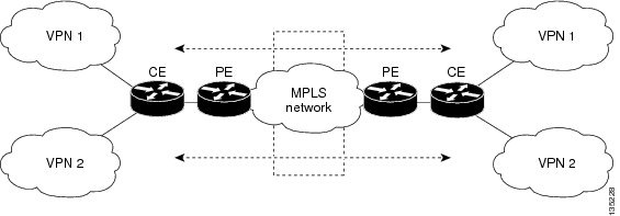
With the MPLS Multi-VRF feature, two or more customers can share one CE device, and only one physical link is used between the CE and the PE devices. The shared CE device maintains separate VRF tables for each customer and routes packets for each customer based on that customer's own routing table. The MPLS Multi-VRF feature extends limited PE device functionality to a CE device, giving it the ability, through the maintenance of separate VRF tables, to extend the privacy and security of a VPN to the branch office.
The figure below shows a configuration where each CE device acts as if it were two CE devices. Because the MPLS Multi-VRF feature is a Layer 3 feature, each interface associated with a VRF must be a Layer 3 interface.
How Packets Are Forwarded in a Network Using the MPLS Multi-VRF Feature
Following is the packet-forwarding process in an MPLS Multi-VRF CE-enabled network, as illustrated in the figure above:
- When the CE receives a packet from a VPN, it looks up the routing table based on the input interface. When a route is found, the CE imposes the MPLS label it received from the PE for that route and forwards the packet to the PE.
- When the ingress PE receives a packet from the CE, it swaps the incoming label with the corresponding label stack and sends it to the MPLS network.
- When an egress PE receives a packet from the network, it swaps the VPN label with the label it earlier had received for the route from the CE, and forwards it to the CE.
- When a CE receives a packet from an egress PE, it uses the incoming label on the packet to forward the packet to the correct VPN.
To configure Multi-VRF, you create a VRF table and then specify the Layer 3 interface associated with that VRF. Next, you configure the routing protocols within the VPN, and between the CE and the PE. BGP is the preferred routing protocol for distributing VPN routing information across the provider's backbone.
The Multi-VRF network has three major components:
- VPN route target communities: These are lists of all other members of a VPN community. You need to configure VPN route targets for each VPN community member.
- Multiprotocol BGP peering of VPN community PE devices: This propagates VRF reachability information to all members of a VPN community. You need to configure BGP peering in all PE devices within a VPN community.
- VPN forwarding: This transports all traffic between VPN community members across a VPN service-provider network.
Considerations for Configuring MPLS Multi-VRF
When BGP is used as the routing protocol, it can also be used for MPLS label exchange between the PE and CE devices. By contrast, if Open Shortest Path First (OSPF), Enhanced Interior Gateway Routing Protocol (EIGRP), RIP, or static routing is used, LDP must be used to signal labels.
To configure the MPLS Multi-VRF feature, create a VRF table, specify the Layer 3 interface associated with that VRF, and then configure the routing protocols within the VPN and between the CE and the PE devices.
Consider these points when configuring the MPLS Multi-VRF feature in your network:
- A device with the MPLS Multi-VRF feature is shared by several customers, and each customer has its own routing table.
- Because each customer uses a different VRF table, the same IP addresses can be reused. Overlapping IP addresses are allowed in different VPNs.
- The MPLS Multi-VRF feature lets several customers share the same physical link between the PE and CE devices. Trunk ports with several VLANs separate packets among the customers. Each customer has its own VLAN.
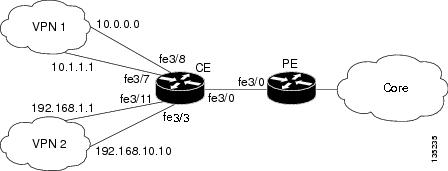
- For the PE device, there is no difference between using the MPLS Multi-VRF feature or using several CE devices. In the figure above, for example, four virtual Layer 3 interfaces are connected to the MPLS Multi-VRF CE device.
- The MPLS Multi-VRF feature does not affect the packet switching rate.
How to Configure MPLS Multi-VRF
- Configuring VRFs
- Configuring BGP as the Routing Protocol
- Configuring PE-to-CE MPLS Forwarding and Signaling with BGP
- Configuring a Routing Protocol Other than BGP
- Configuring PE-to-CE MPLS Forwarding and Signaling with LDP
Configuring VRFs
Perform the following task to configure VRFs on both the PE and CE devices:
If a VRF has not been configured, the device has the following default configuration:
DETAILED STEPS
Configuring BGP as the Routing Protocol
Most routing protocols can be used between the CE and the PE devices. However, external BGP (eBGP) is recommended, because:
- BGP does not require more than one algorithm to communicate with many CE devices.
- BGP is designed to pass routing information between systems run by different administrations.
- BGP makes it easy to pass attributes of the routes to the CE device.
When BGP is used as the routing protocol, it can also be used to handle the MPLS label exchange between the PE and CE devices. By contrast, if OSPF, EIGRP, RIP, or static routing is used, LDP must be used to signal labels.
To configure a BGP PE-to-CE routing session, perform the following steps on the CE and on the PE devices.
DETAILED STEPS
| Command or Action | Purpose | |
|---|---|---|
Step 1 |
enable
Example: Device> enable |
Enables privileged EXEC mode. |
Step 2 |
configure terminal
Example: Device# configure terminal |
Enters global configuration mode. |
Step 3 |
router bgp
autonomous-system-number
Example: Device(config)# router bgp 100 |
Configures the BGP routing process with the autonomous system number passed to other BGP devices, and enters router configuration mode. |
Step 4 |
network
ip-address
mask
network-mask
Example: Device(config-router)# network 10.0.0.0 mask 255.255.255.0 |
Specifies a network and mask to announce using BGP. |
Step 5 |
redistribute ospf
process-id
match internal
Example: Device(config-router)# redistribute ospf 2 match internal |
Sets the device to redistribute OSPF internal routes. |
Step 6 |
network
ip-address
area
area-id
Example: Device(config-router)# network 10.0.0.0 255.255.255.0 area 0 |
Identifies the network address and mask on which OSPF is running, and the area ID of that network address. |
Step 7 |
address-family ipv4 vrf
vrf-name
Example: Device(config-router)# address-family ipv4 vrf v12 |
Identifies the name of the VRF instance that will be associated with the next two commands, and enters VRF address-family mode. |
Step 8 |
neighbor {ip-address |
peer-group-name}
remote-as
as-number
Example: Device(config-router-af)# neighbor 10.0.0.3 remote-as 100 |
Informs this device's BGP neighbor table of the neighbor's address (or peer group name) and the neighbor's autonomous system number. |
Step 9 |
neighbor
address
activate
Example: Device(config-router-af)# neighbor 10.0.0.3 activate |
Activates the advertisement of the IPv4 address-family neighbors. |
Configuring PE-to-CE MPLS Forwarding and Signaling with BGP
If BGP is used for routing between the PE and CE devices, configure BGP to signal the labels on the VRF interfaces of both the CE and PE devices. You must globally enable signaling at the router-configuration level and for each interface:
DETAILED STEPS
| Command or Action | Purpose | |
|---|---|---|
Step 1 |
enable
Example: Device> enable |
Enables privileged EXEC mode. |
Step 2 |
configure terminal
Example: Device# configure terminal |
Enters global configuration mode. |
Step 3 |
router bgp
autonomous-system-number
Example: Device(config)# router bgp 100 |
Configures the BGP routing process with the autonomous system number passed to other BGP devices and enters router configuration mode. |
Step 4 |
address-family ipv4 vrf
vrf-name
Example: Device(config-router)# address-family ipv4 vrf v12 |
Identifies the name of the VRF instance that will be associated with the next two commands and enters address family configuration mode. |
Step 5 |
neighbor {ip-address |
peer-group-name}
remote-as
as-number
Example: Device(config-router-af)# neighbor 10.0.0.3 remote-as 100 |
Informs this device's BGP neighbor table of the neighbor's address (or peer group name) and the neighbor's autonomous system number. |
Step 6 |
neighbor
address
send-label [explicit-null]
Example: Device(config-router-af)# neighbor 10.0.0.3 send-label |
Enables the device to use BGP to distribute MPLS labels along with the IPv4 routes to the peer devices. |
Step 7 |
neighbor
address
activate
Example: Device(config-router-af)# neighbor 10.0.0.3 activate |
Activates the advertisement of the IPv4 address-family neighbors. |
Step 8 |
end
Example: Device(config-router-af)# end |
Exits address family configuration mode and returns to privileged EXEC mode. |
Step 9 |
configure terminal
Example: Device# configure terminal |
Enters global configuration mode. |
Step 10 |
interface
type
number
Example: Device(config)# interface fastethernet3/0.10 |
Enters interface configuration mode for the interface to be used for the BGP session. |
Step 11 |
mpls bgp forwarding
Example: Device(config-if)# mpls bgp forwarding |
Enables MPLS forwarding on the interface. |
Configuring a Routing Protocol Other than BGP
You can use RIP, EIGRP, OSPF or with static routing. This configuration uses OSPF, but the process is the same for other protocols.
If you use OSPF as the routing protocol between the PE and the CE devices, issue the capability vrf-lite command in router configuration mode.
 Note | If OSPF, EIGRP, RIP, or static routing is used, LDP must be used to signal labels. The MPLS Multi-VRF feature is not supported by IGRP nor IS-IS. Multicast cannot be configured on the same Layer 3 interface as the MPLS Multi-VRF feature is configured. |
DETAILED STEPS
| Command or Action | Purpose | |
|---|---|---|
Step 1 |
enable
Example: Device> enable |
Enables privileged EXEC mode. |
Step 2 |
configure terminal
Example: Device# configure terminal |
Enters global configuration mode. |
Step 3 |
router ospf
process-id [vrf
vpn-name]
Example: Device(config)# router ospf 100 vrf v1 |
Enables OSPF routing, specifies a VRF table, and enters router configuration mode. |
Step 4 |
log-adjacency-changes
Example: Device(config-router)# log-adjacency-changes |
(Optional) Logs changes in the adjacency state. This is the default state. |
Step 5 |
redistribute bgp
autonomous-system-number
subnets
Example: Device(config-router)# redistribute bgp 800 subnets |
Sets the device to redistribute information from the BGP network to the OSPF network. |
Step 6 |
network
ip-address
subnet-mask
area
area-id
Example: Device(config-router)# network 10.0.0.0 255.255.255.0 area 0 |
Indicates the network address and mask on which OSPF runs, and the area ID of that network address. |
Step 7 | end
Example: Device(config-router)# end | Exits router configuration mode and returns to privileged EXEC mode. |
Step 8 |
show ip ospf
Example: Device# show ip ospf |
Displays information about the OSPF routing processes. |
Configuring PE-to-CE MPLS Forwarding and Signaling with LDP
If OSPF, EIGRP, RIP, or static routing is used, LDP must be used to signal labels. Perform the following steps to configure PE-to-CE MPLS forwarding and signaling with LDP.
DETAILED STEPS
| Command or Action | Purpose | |
|---|---|---|
Step 1 |
enable
Example: Device> enable |
Enables privileged EXEC mode. |
Step 2 |
configure terminal
Example: Device# configure terminal |
Enters global configuration mode. |
Step 3 |
interface
type
number
Example: Device(config)# interface fastethernet3/0.10 |
Enters subinterface configuration mode for the interface associated with the VRF. |
Step 4 |
mpls ip
Example: Device(config-subif)# mpls ip |
Enables MPLS forwarding of IPv4 packets along normally routed paths for this interface. |
Configuration Examples for MPLS Multi-VRF
- Example Configuring MPLS Multi-VRF on the PE Device
- Example Configuring MPLS Multi-VRF on the CE Device
Example Configuring MPLS Multi-VRF on the PE Device
Configuring VRFs
configure terminal
ip vrf v1
 rd 100:1
 route-target export 100:1
 route-target import 100:1
 exit
ip vrf v2
 rd 100:2
 route-target export 100:2
 route-target import 100:2
 exit
Configuring PE-to-CE Connections Using BGP for Both Routing and Label Exchange
router bgp 100
 address-family ipv4 vrf v2
  neighbor 10.0.0.8 remote-as 800
  neighbor 10.0.0.8 send-label
  neighbor 10.0.0.8 activate
  exit
 address-family ipv4 vrf vl
  neighbor 10.0.0.8 remote-as 800
  neighbor 10.0.0.8 send-label
  neighbor 10.0.0.8 activate
  end
configure terminal
 interface fastethernet3/0.10
  ip vrf forwarding v1
  ip address 10.0.0.3 255.255.255.0
  mpls bgp forwarding
  exit
 interface fastethernet3/0.20
  ip vrf forwarding v2
  ip address 10.0.0.3 255.255.255.0
  mpls bgp forwarding
  exit
Configuring PE-to-CE Connections Using OSPF for Routing and LDP for Label Exchange
router ospf 100 vrf v1
 network 10.0.0.0 255.255.255.0 area 0
 exit
router ospf 101 vrf v2
 network 10.0.0.0 255.255.255.0 area 0
 exit
interface fastethernet3/0.10
 ip vrf forwarding v1
 ip address 10.0.0.3 255.255.255.0
 mpls ip
 exit
interface fastethernet3/0.20
 ip vrf forwarding v2
 ip address 10.0.0.3 255.255.255.0
 mpls ip
 exit
Example Configuring MPLS Multi-VRF on the CE Device
Configuring VRFs
configure terminal
 ip routing
 ip vrf v11
  rd 800:1
  route-target export 800:1
  route-target import 800:1
  exit
 ip vrf v12
  rd 800:2
  route-target export 800:2
  route-target import 800:2
  exit
Configuring CE Device VPN Connections
interface fastethernet3/8
ip vrf forwarding v11
ip address 10.0.0.8 255.255.255.0
exit
interface fastethernet3/11
ip vrf forwarding v12
ip address 10.0.0.8 255.255.255.0
exit
  router ospf 1 vrf v11
 network 10.0.0.0 255.255.255.0 area 0
 network 10.0.0.0 255.255.255.0 area 0
 exit
  router ospf 2 vrf v12
 network 10.0.0.0 255.255.255.0 area 0
 network 10.0.0.0 255.255.255.0 area 0
 exit
Note | If BGP is used for routing between the PE and CE devices, the BGP-learned routes from the PE device can be redistributed into OSPF using the commands in the following example. |
  router ospf 1 vrf v11
 redistribute bgp 800 subnets
 exit
  router ospf 2 vrf v12
 redistribute bgp 800 subnets
 exit
Configuring PE-to-CE Connections Using BGP for Both Routing and Label Exchange
  router bgp 800
 address-family ipv4 vrf v12
neighbor 10.0.0.3 remote-as 100
neighbor 10.0.0.3 send-label
neighbor 10.0.0.3 activate
 exit
 address-family ipv4 vrf vl1
neighbor 10.0.0.3 remote-as 100
neighbor 10.0.0.3 send-label
neighbor 10.0.0.3 activate
 end
  interface fastethernet3/0.10
  ip vrf forwarding v11
  ip address 10.0.0.8 255.255.255.0
  mpls bgp forwarding
  exit
  interface fastethernet3/0.20
  ip vrf forwarding v12
  ip address 10.0.0.8 255.255.255.0
  mpls bgp forwarding
  exit
Configuring PE-to-CE Connections Using OSPF for Routing and LDP for Label Exchange
  router ospf 1 vrf v11
 network 10.0.0.0 255.255.255.0 area 0
 exit
  router ospf 2 vrf v12
 network 10.0.0.0 255.255.255.0 area 0
 exit
  interface fastethernet3/0.10
  ip vrf forwarding v11
  ip address 10.0.0.3 255.255.255.0
  mpls ip
  exit
  interface fastethernet3/0.20
  ip vrf forwarding v12
  ip address 10.0.0.3 255.255.255.0
  mpls ip
  exit
Additional References
Related Documents
Technical Assistance
|
Description |
Link |
|---|---|
|
The Cisco Support and Documentation website provides online resources to download documentation, software, and tools. Use these resources to install and configure the software and to troubleshoot and resolve technical issues with Cisco products and technologies. Access to most tools on the Cisco Support and Documentation website requires a Cisco.com user ID and password. |
Feature Information for MPLS Multi-VRF
The following table provides release information about the feature or features described in this module. This table lists only the software release that introduced support for a given feature in a given software release train. Unless noted otherwise, subsequent releases of that software release train also support that feature.
Use Cisco Feature Navigator to find information about platform support and Cisco software image support. To access Cisco Feature Navigator, go to www.cisco.com/go/cfn. An account on Cisco.com is not required.
| Table 1 | Feature Information for MPLS Multi-VRF |
|
Feature Name |
Releases |
Feature Information |
|---|---|---|
|
MPLS Multi-VRF |
12.1(11)EA1 12.1(20)EW 12.2(4)T 12.2(8)YN 12.2(18)SXD 12.2(25)EWA 12.2(28)SB |
The MPLS Multi-VRF feature allows you to configure and maintain more than one instance of a routing and forwarding table within the same CE device. In Cisco IOS Release 12.1(11)EA1, the Multi-VRF feature was introduced. The feature was integrated into Cisco IOS Release 12.1(20)EW. The feature was integrated into Cisco IOS Release 12.2(4)T. The feature was integrated into Cisco IOS Release 12.2(8)YN. The feature was integrated into Cisco IOS Release 12.2(18)SXD. The feature was integrated into Cisco IOS Release 12.2(25)EWA. Multiprotocol Label Switching support was added in Cisco IOS Release 12.2(28)SB. |
Cisco and the Cisco logo are trademarks or registered trademarks of Cisco and/or its affiliates in the U.S. and other countries. To view a list of Cisco trademarks, go to this URL: www.cisco.com/go/trademarks. Third-party trademarks mentioned are the property of their respective owners. The use of the word partner does not imply a partnership relationship between Cisco and any other company. (1110R)
Any Internet Protocol (IP) addresses and phone numbers used in this document are not intended to be actual addresses and phone numbers. Any examples, command display output, network topology diagrams, and other figures included in the document are shown for illustrative purposes only. Any use of actual IP addresses or phone numbers in illustrative content is unintentional and coincidental.