
 Feedback
Contents
- Dialing to Destinations with the Same IP Address for MPLS VPNs
- Finding Feature Information
- Prerequisites for Dialing to Destinations with the Same IP Address for MPLS VPNs
- Restrictions for Dialing to Destinations with the Same IP Address for MPLS VPNs
- Information About Dialing to Destinations with the Same IP Address for MPLS VPNs
- Introduction to Dialing to Destinations with the Same IP Address for MPLS VPNs
- Benefits of this Feature
- How to Enable Dialing to Destinations with the Same IP Address for MPLS VPNs
- Mapping the VRF and Next-Hop Address to a Dial String
- Verifying the Configuration
- Troubleshooting Tips
- Configuration Examples for Dialing to Destinations with the Same IP Address
- Additional References
- Feature Information for Dialing to Destinations with the Same IP Address
Dialing to Destinations with the Same IP Address for MPLS VPNs
The dialer software in Cisco IOS prior to Release 12.2(8)T had no way to dial two different destinations with the same IP address. More specifically, in networks where a network access server (NAS) supports dialing clients with overlapping addresses, dial-out attempts fail. This module explains how to dial to more than one destination with the same IP address.
- Finding Feature Information
- Prerequisites for Dialing to Destinations with the Same IP Address for MPLS VPNs
- Restrictions for Dialing to Destinations with the Same IP Address for MPLS VPNs
- Information About Dialing to Destinations with the Same IP Address for MPLS VPNs
- How to Enable Dialing to Destinations with the Same IP Address for MPLS VPNs
- Configuration Examples for Dialing to Destinations with the Same IP Address
- Additional References
- Feature Information for Dialing to Destinations with the Same IP Address
Finding Feature Information
Your software release may not support all the features documented in this module. For the latest feature information and caveats, see the release notes for your platform and software release. To find information about the features documented in this module, and to see a list of the releases in which each feature is supported, see the Feature Information Table at the end of this document.
Use Cisco Feature Navigator to find information about platform support and Cisco software image support. To access Cisco Feature Navigator, go to www.cisco.com/go/cfn. An account on Cisco.com is not required.
Prerequisites for Dialing to Destinations with the Same IP Address for MPLS VPNs
Before configuring this feature, you should understand how to configure the following network features:
Refer to the documents listed in the Additional References section for information about configuring these features.
Restrictions for Dialing to Destinations with the Same IP Address for MPLS VPNs
When configuring static routes in an MPLS or MPLS VPN environment, some variations of the ip route and ip route vrf commands are not supported. These variations of the commands are not supported in Cisco IOS releases that support the Tag Forwarding Information Base (TFIB), specifically Cisco IOS Releases 12.xT, 12.xM, and 12.0S. The TFIB cannot resolve prefixes when the recursive route over which the prefixes travel disappears and then reappears. However, the command variations are supported in Cisco IOS releases that support the MPLS Forwarding Infrastructure (MFI), specifically Cisco IOS Release 12.2(25)S and later. Use the following guidelines when configuring static routes.
Supported Static Routes in an MPLS Environment
The following ip route command is supported when you configure static routes in MPLS environment:
ip route destination-prefix mask interface next-hop-address
The following ip route commands are supported when you configure static routes in an MPLS environment and configure load sharing with static nonrecursive routes and a specific outbound interface:
ip route destination-prefix mask interface1 next-hop1
ip route destination-prefix mask interface2 next-hop2
Unsupported Static Routes in an MPLS Environment that Uses the TFIB
The following ip route command is not supported when you configure static routes in an MPLS environment:
ip route destination-prefix mask next-hop-address
The following ip route command is not supported when you configure static routes in an MPLS environment and enable load sharing where the next hop can be reached through two paths:
ip route destination-prefix mask next-hop-address
The following ip route command is not supported when you configure static routes in an MPLS environment and enable load sharing where the destination can be reached through two next hops:
ip route destination-prefix mask next-hop1
ip route destination-prefix mask next-hop2
Use the interface an next-hop arguments when specifying static routes.
Supported Static Routes in an MPLS VPN Environment
The following ip route vrf commands are supported when you configure static routes in a MPLS VPN environment, and the next hop and interface are in the same VRF:
The following ip route vrf commands are supported when you configure static routes in a MPLS VPN environment, and the next hop is in the global table in the MPLS cloud in the global routing table. For example, these commands are supported when the next hop is pointing to the Internet Gateway.
The following ip route commands are supported when you configure static routes in a MPLS VPN environment and enable load sharing with static nonrecursive routes and a specific outbound interfaces:
ip route destination-prefix mask interface1 next-hop1
ip route destination-prefix mask interface2 next-hop2
Unsupported Static Routes in an MPLS VPN Environment that Uses the TFIB
The following ip route command is not supported when you configure static routes in a MPLS VPN environment, the next hop is in the global table in the MPLS cloud within the core, and you enable load sharing where the next hop can be reached through two paths:
ip route vrf vrf-name destination-prefix mask next-hop-address global
The following ip route commands are not supported when you configure static routes in a MPLS VPN environment, the next hop is in the global table in the MPLS cloud within the core, and you enable load sharing where the destination can be reached through two next hops:
ip route vrf destination-prefix mask next-hop1 global
ip route vrf destination-prefix mask next-hop2 global
The following ip route vrf commands are not supported when you configure static routes in an MPLS VPN environment, and the next hop and interface are in the same VRF:
ip route vrf vrf-name destination-prefix mask next-hop1
ip route vrf vrf-name destination-prefix mask next-hop2
Supported Static Routes in an MPLS VPN Environment Where the Next Hop Resides in the Global Table on the CE Router
The following ip route vrf command is supported when you configure static routes in a MPLS VPN environment, and the next hop is in the global table on the CE side. For example, the following command is supported when the destination-prefix is the CE router's loopback address, as in EBGP multihop cases.
ip route vrf vrf-name destination-prefix mask interface next-hop-address
The following ip route commands are supported when you configure static routes in a MPLS VPN environment, the next hop is in the global table on the CE side, and you enable load sharing with static non-recursive routes and a specific outbound interfaces:
ip route destination-prefix mask interface1 nexthop1
ip route destination-prefix mask interface2 nexthop2
Information About Dialing to Destinations with the Same IP Address for MPLS VPNs
- Introduction to Dialing to Destinations with the Same IP Address for MPLS VPNs
- Benefits of this Feature
Introduction to Dialing to Destinations with the Same IP Address for MPLS VPNs
The Cisco IOS dialer software can distinguish between two destinations with the same IP address using information stored in the VRF. This capability is provided to the dialer software by two existing Cisco IOS commands, dialer map and ip route, which have been enhanced to include VPN routing and forwarding (VRF) information.
In previous Cisco IOS releases, the dialer software obtained the telephone number for dial-out based on the destination IP address configured in the dialer map command. Now, the enhanced dialer map command supplies the name of the VRF so that the telephone number to be dialed is based on the VRF name and the destination IP address. The VRF is identified based on the incoming interface of the packet, and is used with the destination IP address defined in the dialer map command to determine the telephone number to be dialed.
The ip route configuration command also includes the VRF information. When a packet arrives in an incoming interface that belongs to a particular VRF, only those ip route commands that correspond to that particular VRF are used to determine the destination interface.
Benefits of this Feature
This feature allows the dialer software to dial out in an MPLS-based VPN. The MPLS VPN model simplifies network routing. For example, rather than needing to manage routing over a complex virtual network backbone composed of many virtual circuits, an MPLS VPN user can employ the backbone of the service provider as the default route in communicating with all other VPN sites.
This default route capability allows several sites to transparently interconnect through the service provider network. One service provider network can support several different IP VPNs, each of which appears to its users as a separate, private network. Within a VPN, each site can send IP packets to any other site in the same VPN, because each VPN is associated with one or more VRFs. The VRF is a key element in the VPN technology, because it maintains the routing information that defines a customer VPN site.
How to Enable Dialing to Destinations with the Same IP Address for MPLS VPNs
Mapping the VRF and Next-Hop Address to a Dial String
Use the following procedure to map a VRF and next-hop address combination to a dial string and thereby allow the dialer software to be VRF-aware for an MPLS VPN.
These commands are only part of the required configuration and show how to map a VRF and next-hop address combination to a dial string. Refer to the documents listed in the Additional References section and the example in the Configuration Examples for Dialing to Destinations with the Same IP Address section for details on where to include these commands in the network configuration.
DETAILED STEPS
Verifying the Configuration
DETAILED STEPS
Configuration Examples for Dialing to Destinations with the Same IP Address
This section provides a configuration example of the feature for a simple network topology shown in the figure below.
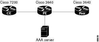
 Note | The network addresses and telephone numbers used in the following configuration are examples only and will not work in an actual network configuration. |
Customer Edge (CE) Router
!
hostname oaktree02
enable secret 5 !1!35Fg$Ep4.D8JGpg7rKxQa49BF9/
!
ip subnet-zero
no ip domain-lookup
!
controller T1 5/0
!
controller T1 5/1
!
interface FastEthernet0/0
 no ip address
 no ip mroute-cache
 duplex auto
 speed auto
!
interface FastEthernet0/1
 no ip address
 no ip mroute-cache
 shutdown
 duplex auto
 speed auto
!
interface Ethernet1/0
 ip address 10.0.58.11 255.255.255.0
 no ip mroute-cache
 half-duplex
!
interface Ethernet1/1
 ip address 50.0.0.2 255.0.0.0
 no ip mroute-cache
 half-duplex
!
interface Ethernet1/2
 no ip address
 no ip mroute-cache
 shutdown
 half-duplex
!
interface Ethernet1/3
 no ip address
 no ip mroute-cache
 shutdown
 half-duplex
!
interface Serial2/0
 no ip address
 no ip mroute-cache
 shutdown
 no fair-queue
 serial restart-delay 0
!
interface Serial2/1
 no ip address
 no ip mroute-cache
 shutdown
 serial restart-delay 0
!
interface Serial2/2
 no ip address
 no ip mroute-cache
 shutdown
 serial restart-delay 0
!
interface Serial2/3
 no ip address
 no ip mroute-cache
 shutdown
 serial restart-delay 0
!
interface FastEthernet4/0
 no ip address
 no ip mroute-cache
 shutdown
 duplex auto
 speed auto
!
ip classless
ip route 0.0.0.0 0.0.0.0 10.0.58.1
ip route 60.0.0.0 255.0.0.0 50.0.0.1
no ip http server
!
!
snmp-server manager
banner motd ^C  AV-8B    OAKTREE^C
alias exec r sh run
!
line con 0
 exec-timeout 0 0
line aux 0
 login
line vty 0 4
 no login
!
end
Provider Edge (PE) Router
hostname pinetree02
!
aaa new-model
!
!
aaa authentication login con-log none
aaa authentication ppp default group radius
aaa authorization network default group radius
aaa session-id common
enable secret 5 $1$7KlA$xpC8l4dJCZogbzZvGUtFl/
!
username rubbertree02 password 0 Hello
ip subnet-zero
!
no ip domain-lookup
!
ip vrf yellow
 rd 100:1
ip cef
virtual-profile aaa
isdn switch-type primary-5ess
!
controller T1 3/0
 framing esf
 linecode b8zs
 pri-group timeslots 1-24
!
controller T1 3/1
 framing esf
 linecode b8zs
!
controller T1 3/2
 framing esf
 linecode b8zs
!
controller T1 3/3
 framing esf
 linecode b8zs
!
controller T1 3/4
 framing esf
 linecode b8zs
!
controller T1 3/5
 framing esf
 linecode b8zs
!
controller T1 3/6
 framing esf
 linecode b8zs
!
controller T1 3/7
 framing esf
 linecode b8zs
!
interface Loopback0
 ip vrf forwarding yellow
 ip address 70.0.0.1 255.0.0.0
!
interface FastEthernet1/0
 no ip address
 shutdown
 duplex half
!
interface Ethernet2/0
 ip address 10.0.58.3 255.255.255.0
 duplex full
!
interface Ethernet2/1
 ip vrf forwarding yellow
 ip address 50.0.0.1 255.0.0.0
 duplex half
!
interface Ethernet2/2
 no ip address
 shutdown
 duplex half
!
interface Ethernet2/3
 no ip address
 shutdown
 duplex half
!
interface Serial3/0:23
 description phone# 555-3123
 no ip address
 encapsulation ppp
 dialer rotary-group 0
 dialer-group 1
 isdn switch-type primary-5ess
 ppp authentication chap
!
interface Serial4/0
 no ip address
 shutdown
 no fair-queue
!
interface Dialer0
 ip address negotiated
 encapsulation ppp
 dialer in-band
 dialer map ip 60.0.0.12 vrf yellow name rubbertree02 5552171
 dialer map ip 60.0.0.2 5552172
 dialer-group 1
 ppp authentication chap
!
ip classless
ip route 0.0.0.0 0.0.0.0 10.0.58.1
ip route 60.0.0.2 255.255.255.255 Dialer0
ip route vrf yellow 60.0.0.0 255.0.0.0 Dialer0 permanent
no ip http server
ip pim bidir-enable
!
ip director cache time 60
dialer-list 1 protocol ip permit
!
radius-server host 172.19.192.89 auth-port 1645 acct-port 1646 key rad123
radius-server retransmit 3
call rsvp-sync
!
no mgcp timer receive-rtcp
!
mgcp profile default
!
dial-peer cor custom
!
gatekeeper
 shutdown
!
banner motd ^C   F/A-18    PINETREE ^C
!
line con 0
 exec-timeout 0 0
 login authentication con-log

line aux 0
line vty 5 15
!
end
Peer Router
hostname rubbertree02
!
logging buffered 32000 debugging
enable secret 5 $1$RCKC$scgtdlaDzjSyUVAi7KK5Q.
enable password Windy
!
username pinetree02 password 0 Hello
!
ip subnet-zero
no ip domain-lookup
!
isdn switch-type basic-5ess
!
interface Ethernet0
 ip address 10.0.58.9 255.255.255.0
 no ip route-cache
!
interface BRI0
 description phone# 555-2171
 ip address 60.0.0.12 255.0.0.0
 encapsulation ppp
 no ip route-cache
 dialer map ip 60.0.0.11 5553123
 dialer map ip 60.0.0.2 5552172
 dialer-group 1
 isdn switch-type basic-5ess
 isdn fast-rollover-delay 45
!
ip default-gateway 10.0.58.1
ip classless
ip route 0.0.0.0 0.0.0.0 10.0.58.1
ip route 50.0.0.0 255.0.0.0 70.0.0.1
no ip http server
!
dialer-list 1 protocol ip permit
no cdp run
banner motd ^C   F-4B   RUBBERTREE^C
!
line con 0
 exec-timeout 0 0
line vty 0 4
 password Windy
 login
!
end
Additional References
MIBs
RFCs
|
RFC |
Title |
|---|---|
|
RFC 1164 |
Application of the Border Gateway Protocol in the Internet |
|
RFC 1171 |
A Border Gateway Protocol 4 |
|
RFC 1700 |
Assigned Numbers |
|
RFC 1966 |
BGP Route Reflection: An Alternative to Full Mesh IBGP |
|
RFC 2283 |
Multiprotocol Extensions for BGP-4 |
|
RFC 2547 |
BGP/MPLS VPNs |
|
RFC 2842 |
Capabilities Advertisement with BGP-4 |
|
RFC 2858 |
Multiprotocol Extensions for BGP-4 |
Technical Assistance
|
Description |
Link |
|---|---|
|
The Cisco Technical Support website contains thousands of pages of searchable technical content, including links to products, technologies, solutions, technical tips, and tools. Registered Cisco.com users can log in from this page to access even more content. The Cisco Support website provides extensive online resources, including documentation and tools for troubleshooting and resolving technical issues with Cisco products and technologies. To receive security and technical information about your products, you can subscribe to various services, such as the Product Alert Tool (accessed from Field Notices), the Cisco Technical Services Newsletter, and Really Simple Syndication (RSS) Feeds. Access to most tools on the Cisco Support website requires a Cisco.com user ID and password. |
Feature Information for Dialing to Destinations with the Same IP Address
The following table provides release information about the feature or features described in this module. This table lists only the software release that introduced support for a given feature in a given software release train. Unless noted otherwise, subsequent releases of that software release train also support that feature.
Use Cisco Feature Navigator to find information about platform support and Cisco software image support. To access Cisco Feature Navigator, go to www.cisco.com/go/cfn. An account on Cisco.com is not required.
| Table 1 | Feature Information for Dialing to Destinations with the Same IP Address |
|
Feature Name |
Releases |
Feature Configuration Information |
|---|---|---|
|
Dialer Map VRF-Aware for MPLS VPNs |
12.2(8)T |
The Cisco IOS dialer software is "VRF-aware for an MPLS VPN," which means that it can distinguish between two destinations with the same IP address using information stored in the VRF. |
Cisco and the Cisco logo are trademarks or registered trademarks of Cisco and/or its affiliates in the U.S. and other countries. To view a list of Cisco trademarks, go to this URL: www.cisco.com/go/trademarks. Third-party trademarks mentioned are the property of their respective owners. The use of the word partner does not imply a partnership relationship between Cisco and any other company. (1110R)
Any Internet Protocol (IP) addresses and phone numbers used in this document are not intended to be actual addresses and phone numbers. Any examples, command display output, network topology diagrams, and other figures included in the document are shown for illustrative purposes only. Any use of actual IP addresses or phone numbers in illustrative content is unintentional and coincidental.