IPv6 VPN over MPLS

Contents

IPv6 VPN over MPLS

Last Updated: March 27, 2012

The Border Gateway Protocol over Multiprotocol Label Switching VPN feature is an implementation of the provider edge (PE)-based VPN model. In principle, there is no difference between IPv4 and IPv6 VPNs. In both IPv4 and IPv6, multiprotocol Border Gateway Protocol (BGP) is the center of the Multiprotocol Label Switching (MPLS) VPN for IPv6 (VPNv6) architecture. It is used to distribute IPv6 routes over the service provider backbone, using the same procedures to work with overlapping addresses, redistribution policies, and scalability issues.

Finding Feature Information

Your software release may not support all the features documented in this module. For the latest feature information and caveats, see the release notes for your platform and software release. To find information about the features documented in this module, and to see a list of the releases in which each feature is supported, see the Feature Information Table at the end of this document.

Use Cisco Feature Navigator to find information about platform support and Cisco software image support. To access Cisco Feature Navigator, go to www.cisco.com/go/cfn. An account on Cisco.com is not required.

Prerequisites for IPv6 VPN over MPLS

Your network must be running the following services before you configure IPv6 VPN operation:

  • MPLS in provider backbone devices
  • MPLS with VPN code in provider devices with VPN PE devices
  • BGP in all devices providing a VPN service
  • Cisco Express Forwarding switching in every MPLS-enabled device
  • Class of Service (CoS) feature

Restrictions for IPv6 VPN over MPLS

6VPE supports an MPLS IPv4-signaled core. An MPLS IPv6-signaled core is not supported.

Information About IPv6 VPN over MPLS

IPv6 VPN over MPLS Overview

Multiprotocol BGP is the center of the MPLS IPv6 VPN architecture in both IPv4 and IPv6. It is used to distribute IPv6 routes over the service provider backbone, using the same procedures to work with overlapping addresses, redistribution policies, and scalability issues.

Although IPv6 should not have overlapping address space, IPv6 addresses are prepended with a route distinguisher (RD). A network layer reachability information (NLRI) 3-tuple format (which contains length, IPv6 prefix, and label) is defined to distribute these routes using multiprotocol BGP. The extended community attribute (for example., the route target) is used to control redistribution of routing information by tagging exported routes and filtering imported ones.

For scalability, route reflectors can be used to concentrate routing paths and avoid a full PE mesh. BGP features in IPv6, such as route refresh, automatic route filtering, and outbound route filtering, help reduce the number of routes held in each PE. This document focuses on the following differences between IPv6 and IPv4:

  • Creation of a new multiprotocol BGP IPv6 VPN address family and specification of a IPv6 VPN address format
  • Specification of a new IPv6 VPN NLRI
  • Specification of BGP next-hop encoding when the device has an IPv4-based MPLS core

Some IPv6 VPN features, such as interprovider and Carrier Supporting Carrier (CSC) topologies, are specific to BGP-MPLS IPv6 VPN. Others, such as the link between Autonomous System Boundary Routers (ASBRs), might support IPv4 only, IPv6 only, or both, regardless of the address family being transported.

Addressing Considerations for IPv6 VPN over MPLS

Regardless of the VPN model deployed, an addressing plan must be defined for the VPN that allows hosts to communicate with other sites using one site within one VPN, as well as with public resources.

VPN IPv4 sites often use private addressing for their addressing plan. These addresses do not need to be registered, and they are not routable on the public network. Whenever a host within a private site needs to access a public domain, it goes through a device that finds a public address on its behalf. With IPv4, this can be a network address translator or an application proxy.

Given the larger address space available with IPv6, the easiest approach to IPv6 addressing is to use IPv6 global addresses for the private addressing plan. Another approach is to use unique local addresses (ULAs). ULAs are easy to filter at site boundaries based on their scope. ULAs are also Internet service provider (ISP)-independent and can be used for communications inside a site without any permanent or intermittent Internet connectivity.

In 6VPE, ULAs are treated as regular global addresses. The device configuration filters ULA prefixes to prevent them from appearing in the public domain. Link-local addresses on the peer will not be announced by BGP (IPv6 or IPv6 VPN) speakers.

A host within a private site that needs to access a public domain can do so through an IPv6 application proxy (such as a web proxy for accessing web pages), which accesses the public resource on the host's behalf with a global routable address, or the host can use a public address of its own. In the latter case, if ULAs have been deployed, the IPv6 host also is configured with a routable global address. A source address selection algorithm is used to select one or the other, based on the destination address.

Basic IPv6 VPN over MPLS Functionality

IPv6 VPN takes advantage of the coexistence between IPv6 and IPv4 by leveraging an existent MPLS IPv4 core network:

IPv6 VPN Architecture Overview

The figure below illustrates the important aspects of the IPv6 VPN architecture.

Figure 1Simple IPv6 VPN Architecture


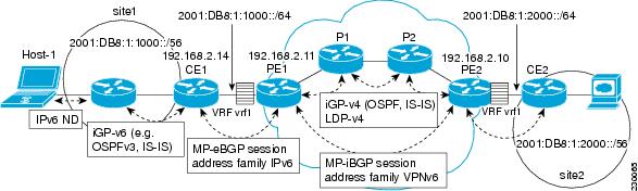
The CE devices are connected to the provider's backbone using PE devices. The PE devices are connected using provider (P1 and P2 in the figure above) devices. The provider (P) devices are unaware of VPN routes, and, in the case of 6VPE, might support only IPv4. Only PE devices perform VPN-specific tasks. For 6VPE, the PE devices are dual-stack (IPv4 and IPv6) devices.

The routing component of the VPN operation is divided into core routing and edge routing. Core routing, which involves PE devices and P devices, typically is performed by an IPv4 Interior Gateway Protocol (IGP) such as Open Shortest Path First (OSPF) or Intermediate System-to-Intermediate System (IS-IS). In the figure above, the IGP distributes only routes internal to the provider's autonomous system. The core routing enables connectivity among P and PE devices.

Edge routing takes place in two directions: routing between PE pairs and routing between a PE and a CE. Routing between PE pairs is achieved using multiprotocol internal BGP (iBGP) using the IPv6 VPN address family. This method distributes routes learned from CEs through PE-CE routing, using appropriate route export policies at the ingress PE device and appropriate route import policies at the egress PE device.

Routing between the CE and its PE is achieved using a routing protocol that is VPN routing and forwarding (VRF) aware. Static routes, external BGP (eBGP), and Enhanced Interior Gateway Routing Protocol (EIGRP) are VRF-instance aware. In the figure above, eBGP is used between the CE (CE1) and the PE (PE1). At the same time, the CE runs an IPv6 IGP within the VPN site (site1 in the figure above). The CE redistributes IGP routes into multiprotocol-eBGP address family IPv6. At the PE, these routes are installed in the VRF named vrf1, and forwarded to the remote PEs (PE2 in the figure above), according to export policies defined for this VRF.

IPv6 VPN Next Hop

When the device announces a prefix using the MP_REACH_NLRI attribute, the MP-BGP running on one PE inserts a BGP next hop in the update message sent to a remote PE. This next hop is either propagated from the received update (for instance, if the PE is a route reflector), or it is the address of the PE sending the update message (the egress PE).

For the IPv6 VPN address family, the next hop must be an IPv6 VPN address, regardless of the nature of the network between the PE speakers. Because the RD has no significance (the address is not part of any VPN), it is set to 0. If the provider network is a native IPv6 network, the remaining part of the next hop is the IPv6 address of the egress PE. Otherwise, it is an IPv4 address used as an IPv6-mapped address (for example, ::FFFF:IPv4-address).

MPLS Forwarding

When it receives IPv6 traffic from one customer site, the ingress PE device uses MPLS to tunnel IPv6 VPN packets over the backbone toward the egress PE device identified as the BGP next hop. The ingress PE device prepends the IPv6 packets with the outer and inner labels before putting the packet on the egress interface.

Under normal operation, a P device along the forwarding path does not look inside the frame beyond the first label. The P device either swaps the incoming label with an outgoing one or removes the incoming label if the next device is a PE device. Removing the incoming label is called penultimate hop popping. The remaining label (BGP label) is used to identify the egress PE interface toward the customer site. The label also hides the protocol version (IPv6) from the last P device, which it would otherwise need to forward an IPv6 packet.

A P device is ignorant of the IPv6 VPN routes. The IPv6 header remains hidden under one or more MPLS labels. When the P device receives an MPLS-encapsulated IPv6 packet that cannot be delivered, it has two options. If the P device is IPv6 aware, it exposes the IPv6 header, builds an Internet Control Message Protocol (ICMP) for IPv6 message, and sends the message, which is MPLS encapsulated, to the source of the original packet. If the P device is not IPv6 aware, it drops the packet.

6VPE over GRE Tunnels

In some Cisco software releases, the ingress PE device uses IPv4 generic routing encapsulation (GRE) tunnels combined with 6VPE over MPLS to tunnel IPv6 VPN packets over the backbone toward the egress PE device identified as the BGP next hop.

VRF Concepts

A virtual routing and forwarding (VRF) entity works with a private customer-specific Routing Information Base (RIB) and Forwarding Information Base (FIB). Although IPv4 and IPv6 routing tables are distinct, it is convenient for the two protocols to share the same VRF for a specific customer.

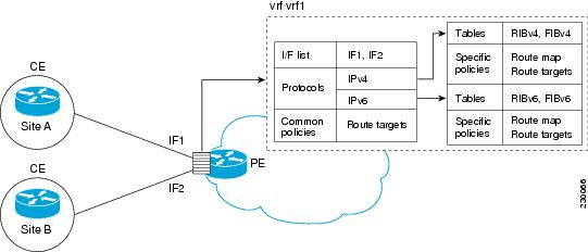
IPv6 VPN customers are likely to be existing VPNv4 customers that are either deploying dual-stack hosts and devices or shadowing some of their IPv4 infrastructure with IPv6 nodes. Several deployment models are possible. Some customers use separate logical interfaces for IPv4 and IPv6 and define separate VRFs on each. Although this approach provides flexibility to configure separate policies for IPv4 and IPv6, it prevents sharing the same policy. Another approach, the multiprotocol VRF, keeps a single VRF on the PE-CE interface, and enables it for IPv4, IPv6, or both. It is then possible to define common or separate policies for each IP version. With this approach, a VRF is better defined as the set of tables, interfaces, and policies found at the PE, and is used by sites of a particular VPN connected to this PE.

The figure below illustrates the multiprotocol VRF, in which the VRF named vrf1is enabled for both IPv4 and IPv6 and is associated with two interfaces (IF1, IF2), two sets of tables (IPv4 RIB and FIB and IPv6 RIB and FIB), and a set of common or distinct policies.

Figure 2Multiprotocol VRF


IPv6 VPN Scalability

PE-based VPNs such as BGP-MPLS IPv6 VPN scale better than CE-based VPNs. A network designer must consider scaling when designing the network. The following points need to be considered:

  • Routing table size, which includes the size of VRF tables and BGP tables
  • Number of BGP sessions, which grows as a square number of PEs

Routing table size concerns occur with PEs that handle many customer sites. Not only do these PEs have one RIB and FIB per connected customer, but also the PEs' BGP tables, which total all entries from individual VRFs, grow accordingly. Another scalability problem occurs when the number of PEs in the provider network grows beyond a certain level. Assuming that a significant number of sites belonging to the same VPN are spread over many PEs, the number of multiprotocol BGP sessions may rapidly become prohibitive: (n -1) x n /2, where n is the number of PEs.

The following features are included in IPv6 VPN over MPLS:

  • Route refresh and automatic route filtering--Limits the size of routing tables, because only routes imported into a VRF are kept locally. When the import policy changes, a route refresh can be sent to query a retransmission of routing updates.
  • Outbound route filtering (ORF)--Allows the ingress PE to advertise filters to the egress PE so that updates are not sent unnecessarily over the network.
  • Route reflectors--Route reflectors (RRs) are iBGP peers that propagate iBGP routes learned from other iBGP peers. RRs are used to concentrate iBGP sessions.

Advanced IPv6 MPLS VPN Functionality

Advanced MPLS features such as accessing the Internet from a VPN for IPv4, multiautonomous-system backbones, and CSCs are generally the same for IPv6 as for IPv4. However, there are differences in addressing and in the way 6VPE operates over an IPv4 backbone.

The following sections describe concepts for advanced IPv6 MPLS VPN functionality:

Internet Access

Most VPN sites require access to the Internet. RFC 4364 describes a set of models for enabling IPv4 and IPv6 VPN access to the Internet. In one model, one interface is used by the CE to connect to the Internet and a different one to connect to the VRF. Another model is in which all Internet routes are redistributed into the VRF; however, this approach has the disadvantage of requiring the Internet routes be replicated in each VRF.

In one scenario, a static route is inserted into the VRF table, with a next hop that points to the Internet gateway found in the IPv6 default table. The figure below illustrates this scenario, in which Internet access is provided to the customer in the VRF named vrf1.

Figure 3Internet Access Topology


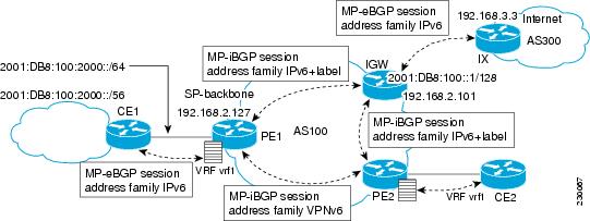
A customer site that has access public resources over the Internet must be known by a public prefix. Unlike IPv4, IPv6 does not offer a Network Address Translation (NAT) mechanism that translates private addresses into public addresses when leaving the site boundaries. This implies that hosts within the site speak with public addresses and appear in the public domain.

For outbound traffic, the default route configured in the VRF table at ingress PE (PE1) directs traffic for destinations outside the VPN to the Internet gateway.

For inbound traffic, a route must exist at the Internet gateway to direct the traffic for a customer site via its PE of attachment (PE1 in the figure above). This route can be distributed by the ingress PE (PE1) using multiprotocol iBGP (with the IPv6 address family configuration), so no specific configuration is needed on a per-VPN PE basis at the Internet gateway. Nevertheless, for inbound traffic at PE1, a route must exist in the default table for the customer site global prefix pointing to the VRF of the site.

Multiautonomous-System Backbones

The problem of interprovider VPNs is similar for IPv6 and IPv4, assuming that IPv6 was deployed everywhere IPv4 was deployed.

In IPv6 deployments that cross autonomous system boundaries, providers may have to obtain a peering model, or work with the peering model put in place for VPNv4.

The figure below illustrates interprovider scenarios in IPv6 VPN.

Figure 4Interprovider Scenarios


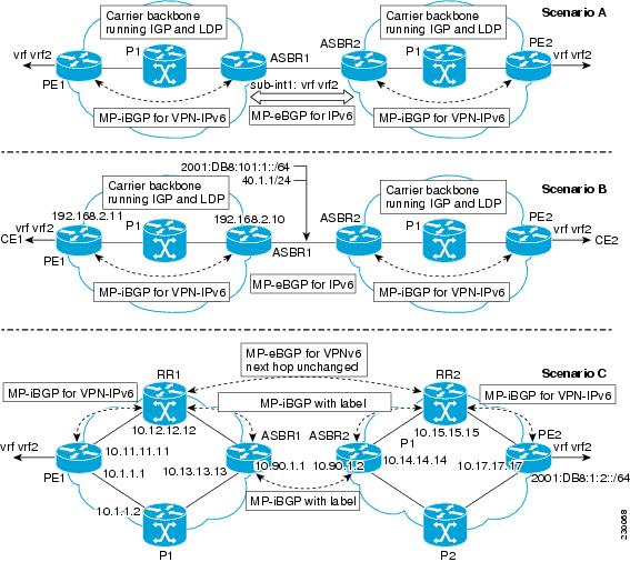
Depending on the network protocol used between ASBRs, the three scenarios shown in the figure above can have several implementation options. For instance, scenario B, which suggests a multiprotocol eBGP IPv6 VPN peering between ASBRs, could use either an IPv6 or an IPv4 link.

In scenario C, multihop multiprotocol eBGP redistributes IPv6 VPN routes across route reflectors in different autonomous systems. Labeled IPv4 routes to the PEs (in the 6VPE case) need to be advertised across ASBRs so that a complete labeled switch path is set up end to end.

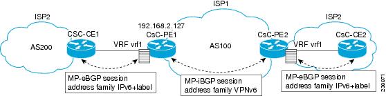
Carrier Supporting Carriers

The CSC feature provides VPN access to a customer service provider, so this service needs to exchange routes and send traffic over the ISP MPLS backbone. The only difference from a regular PE is that it provides MPLS-to-MPLS forwarding on the CSC-CE to CSC-PE interface, rather than IP-to-MPLS forwarding.

The figure below highlights the two ISPs' interface.

Figure 5CSC 6VPE Configuration Example


How to Configure IPv6 VPN over MPLS

Configuring a Virtual Routing and Forwarding Instance for IPv6

A VRF is an address family-independent object that can be enabled and configured for each of the supported address families. Configuring a VRF consists of the following three steps:

  • Configuring the address-family-independent part of the VRF
  • Enabling and configuring IPv4 for the VRF
  • Enabling and configuring IPv6 for the VRF

A VRF is given a name and an RD. The RD is configured outside the context of the address family, although the RD is used to distinguish overlapping addresses within the context of a particular BGP address family. Having separate RDs for IPv4 VPN addresses and IPv6 VPN addresses does not matter. On Cisco devices, the RDs are the same to simplify configuration and VPN management.

Users can configure policies in common between IPv4 and IPv6 when not using an address family context. This feature is shared route targets (import and export), and it is useful in a migration scenario, where IPv4 policies already are configured and IPv6 policies should be the same as the IPv4 policies.

The IPv4 and IPv6 address family can each be enabled and configured separately. Note that the route-target policies entered at this level override global policies that might have been specified during address family-independent configuration.

SUMMARY STEPS

1.    enable

2.    configure terminal

3.    mls ipv6 vrf

4.    vrf definition vrf-name

5.    rd route-distinguisher

6.    route-target {import| export| both} route-target-ext-community

7.    exit

8.    address-family ipv4 [mdt | multicast | tunnel | unicast [vrf vrf-name] | vrf vrf-name]

9.    route-target {import | export | both} route-target-ext-community

10.    exit

11.    address-family ipv6 [vrf vrf-name] [unicast | multicast]

12.    route-target {import| export| both} route-target-ext-community


DETAILED STEPS
 Command or ActionPurpose
Step 1
enable


Example:

Device> enable


Enables privileged EXEC mode.

  • Enter your password if prompted.
 
Step 2
configure terminal


Example:

Device# configure terminal


Enters global configuration mode.

 
Step 3
mls ipv6 vrf


Example:

Device(config)# mls ipv6 vrf


Enables IPv6 globally in a VRF.

 
Step 4
vrf definition vrf-name


Example:

Device(config)# vrf definition vrf1


Configures a VPN VRF routing table and enters VRF configuration mode.

 
Step 5
rd route-distinguisher


Example:

Device(config-vrf)# rd 100:1


Specifies the RD for a VRF.

 
Step 6
route-target {import| export| both} route-target-ext-community


Example:

Device(config-vrf)# route target import 100:10


Specifies the route target VPN extended communities for both IPv4 and IPv6.

 
Step 7
exit


Example:

Device(config-vrf)# exit


Exits VRF configuration mode.

 
Step 8
address-family ipv4 [mdt | multicast | tunnel | unicast [vrf vrf-name] | vrf vrf-name]


Example:

Device(config)# address-family ipv4


Enters address family configuration mode to configure a routing session using standard IPv4 address prefixes.

 
Step 9
route-target {import | export | both} route-target-ext-community


Example:

Device(config-vrf-af)# route target import 100:11


Specifies the route target VPN extended communities specific to IPv4.

 
Step 10
exit


Example:

Device(config-vrf-af)# exit


Exits address family configuration mode on this VRF.

 
Step 11
address-family ipv6 [vrf vrf-name] [unicast | multicast]


Example:

Device(config-vrf)# address-family ipv6


Enters address family configuration mode for configuring routing sessions such as BGP that use standard IPv6 address prefixes.

 
Step 12
route-target {import| export| both} route-target-ext-community


Example:

Device(config-vrf-af)# route target import 100:12


Specifies the route target VPN extended communities specific to IPv6.


Binding a VRF to an Interface

To specify which interface belongs to which VRF, use the vrf forwarding command for both IPv4 and IPv6. An interface cannot belong to more than one VRF. When the interface is bound to a VRF, previously configured addresses (IPv4 and IPv6) are removed, and they must be reconfigured.

SUMMARY STEPS

1.    enable

2.    configure terminal

3.    interface type number

4.    vrf forwarding vrf-name

5.    ip address ip-address mask [secondary]

6.    ipv6 address {ipv6-address / prefix-length | prefix-name sub-bits / prefix-length}


DETAILED STEPS
 Command or ActionPurpose
Step 1
enable


Example:

Device> enable


Enables privileged EXEC mode.

  • Enter your password if prompted.
 
Step 2
configure terminal


Example:

Device# configure terminal


Enters global configuration mode.

 
Step 3
interface type number


Example:

Device(config)# interface Ethernet 0/0


Specifies an interface type and number, and places the device in interface configuration mode.

 
Step 4
vrf forwarding vrf-name


Example:

Device(config-if)# vrf forwarding vrf1


Associates a VPN VRF with an interface or subinterface.

  • Any address, IPv4 or IPv6, that was configured prior to entering this command will be removed.
 
Step 5
ip address ip-address mask [secondary]


Example:

Device(config-if)# ip address 10.10.10.1 255.255.255.0


Configures an IPv4 address on the interface.

 
Step 6
ipv6 address {ipv6-address / prefix-length | prefix-name sub-bits / prefix-length}


Example:

Device(config-if)# ipv6 address 2001:DB8:100:1::1/64


Configures an IPv6 address on the interface.


Configuring a Static Route for PE-to-CE Routing

SUMMARY STEPS

1.    enable

2.    configure terminal

3.    ipv6 route [vrf vrf-name] ipv6-prefix / prefix-length {ipv6-address | interface-type interface-number [ipv6-address]} [nexthop-vrf [vrf-name1 | default]] [administrative-distance] [administrative-multicast-distance | unicast | multicast] [next-hop-address] [tag tag]


DETAILED STEPS
 Command or ActionPurpose
Step 1
enable


Example:

Device> enable


Enables privileged EXEC mode.

  • Enter your password if prompted.
 
Step 2
configure terminal


Example:

Device# configure terminal


Enters global configuration mode.

 
Step 3
ipv6 route [vrf vrf-name] ipv6-prefix / prefix-length {ipv6-address | interface-type interface-number [ipv6-address]} [nexthop-vrf [vrf-name1 | default]] [administrative-distance] [administrative-multicast-distance | unicast | multicast] [next-hop-address] [tag tag]


Example:

Device(config)# ipv6 route vrf vrf1 ::/0 2001:DB8:200::1 nexthop-vrf default


Installs the specified IPv6 static route using the specified next hop.


Configuring eBGP PE-to-CE Routing Sessions

SUMMARY STEPS

1.    enable

2.    configure terminal

3.    router bgp autonomous-system-number

4.    address-family ipv6 [vrf vrf-name] [unicast | multicast]

5.    neighbor {ip-address | ipv6-address | peer-group-name} remote-as as-number

6.    neighbor { p-address | peer-group-name | ipv6-address} activate


DETAILED STEPS
 Command or ActionPurpose
Step 1
enable


Example:

Device> enable


Enables privileged EXEC mode.

  • Enter your password if prompted.
 
Step 2
configure terminal


Example:

Device# configure terminal


Enters global configuration mode.

 
Step 3
router bgp autonomous-system-number


Example:

Device(config)# router bgp 100


Configures the BGP routing process.

 
Step 4
address-family ipv6 [vrf vrf-name] [unicast | multicast]


Example:

Device(config-router)# address-family ipv6 vrf vrf1


Enters address family configuration mode.

 
Step 5
neighbor {ip-address | ipv6-address | peer-group-name} remote-as as-number


Example:

Device(config-router-af)# neighbor 2001:DB8:100:1::2 remote-as 200


Adds an entry to the multiprotocol BGP neighbor table.

 
Step 6
neighbor { p-address | peer-group-name | ipv6-address} activate


Example:

Device(config-router-af)# neighbor 2001:DB8:100:1::2 activate


Enables the exchange of information for this address family with the specified BGP neighbor.


Configuring the IPv6 VPN Address Family for iBGP

SUMMARY STEPS

1.    enable

2.    configure terminal

3.    router bgp autonomous-system-number

4.    neighbor {ip-address | ipv6-address | peer-group-name} remote-as as-number

5.    neighbor {ip-address | ipv6-address | peer-group-name} update-source interface-type interface-number

6.    address-family vpnv6 [unicast]

7.    neighbor {ip-address | peer-group-name | ipv6-address} activate

8.    neighbor {ip-address | ipv6-address | peer-group-name} send-community [both | standard | extended]

9.    exit


DETAILED STEPS
 Command or ActionPurpose
Step 1
enable


Example:

Device> enable


Enables privileged EXEC mode.

  • Enter your password if prompted.
 
Step 2
configure terminal


Example:

Device# configure terminal


Enters global configuration mode.

 
Step 3
router bgp autonomous-system-number


Example:

Device(config)# router bgp 100


Configures the BGP routing process.

 
Step 4
neighbor {ip-address | ipv6-address | peer-group-name} remote-as as-number


Example:

Device(config-router)# neighbor 192.168.2.11 remote-as 100


Adds an entry to the multiprotocol BGP neighbor table.

  • In IPv6 VPN, the peer address typically is an IPv4 address, in order to enable the BGP session to be transported over the IPv4-based core network.
 
Step 5
neighbor {ip-address | ipv6-address | peer-group-name} update-source interface-type interface-number


Example:

Device(config-router)# neighbor 192.168.2.11 update-source Loopback 0


Enables the BGP session to use a source address on the specified interface.

 
Step 6
address-family vpnv6 [unicast]


Example:

Device(config-router)# address-family vpnv6


Places the device in address family configuration mode for configuring routing sessions.

 
Step 7
neighbor {ip-address | peer-group-name | ipv6-address} activate


Example:

Device(config-router-af)# neighbor 192.168.2.11 activate


Enables the exchange of information for this address family with the specified BGP neighbor.

 
Step 8
neighbor {ip-address | ipv6-address | peer-group-name} send-community [both | standard | extended]


Example:

Device(config-router-af)# neighbor 192.168.2.11 send-community extended


Specifies that a communities attribute should be sent to the BGP neighbor.

 
Step 9
exit


Example:

Device(config-router-af)# exit


Exits address family configuration mode.


Configuring Route Reflectors for Improved Scalability

In this task, two RRs are configured for redundancy reasons. Deploying RRs improves scalability by drastically reducing the number of BGP sessions. One RR usually peers with many iBGP speakers, preventing a full mesh of BGP sessions.

In an MPLS-based core, RRs are not part of the label switch paths and can be located anywhere in the network. For example, in a flat RR design, RRs can be deployed at Level 1 points of presence (POPs) and peer together in a full-mesh topology. In a hierarchical RR design, RRs could be deployed at Level 1 and Level 2 POPs, with Level 1 POPs peering together and with Level 2 RRs.

In a typical case where 6VPE is deployed in a preexisting MPLS network (for example, providing VPNv4 services), it is likely that some RR design is already in place, and a similar RR infrastructure for IPv6 VPN services can be deployed. The figure below illustrates the main peering points between the RR in the ISP POP and the set of its RR clients.

Figure 6Route Reflector Peering Design


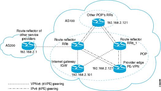
The following list of BGP RR clients must be configured at each IPv6 RR (RR6 and RR6_1 in the figure above) device, at each POP:

  • PE devices (PE-VPN) of the POP providing IPv6 VPN access to the ISP customers. This includes both IPv6 VPN (6VPE) peering for interconnecting customer sites and IPv6 peering (6PE) for providing Internet access to VPN customers (see the Configuring Internet Access).
  • Internet gateway (IGW) located in the POP in order to provide PE customers with access to the IPv6 Internet (see the Configuring Internet Access).
  • RRs from other service providers. This feature is used to provide interautonomous-system connectivity, and it includes both IPv6 and IPv6 VPN peering. This service is described in the Configuring a Multiautonomous-System Backbone for IPv6 VPN section.
  • RRs in other POPs. All RRs peer together, with both IPv6 and IPv6 VPN address families enabled.
SUMMARY STEPS

1.    enable

2.    configure terminal

3.    router bgp autonomous-system-number

4.    neighbor {ip-address | ipv6-address | peer-group-name} remote-as as-number

5.    neighbor {ip-address | ipv6-address | peer-group-name} update-source interface-type interface-number

6.    neighbor {ip-address | ipv6-address | peer-group-name} remote-as as-number

7.    neighbor {ip-address | ipv6-address | peer-group-name} update-source interface-type interface-number

8.    neighbor {ip-address | ipv6-address | peer-group-name} remote-as as-number

9.    neighbor {ip-address | ipv6-address | peer-group-name} update-source interface-type interface-number

10.    neighbor {ip-address | ipv6-address | peer-group-name} remote-as as-number

11.    neighbor {ip-address | ipv6-address | peer-group-name} update-source interface-type interface-number

12.    neighbor {ip-address | ipv6-address| peer-group-name} ebgp-multihop [ttl]

13.    address-family ipv6

14.    neighbor {ip-address | peer-group-name | ipv6-address} activate

15.    neighbor { ip-address | ipv6-address | peer-group-name} send-label

16.    neighbor {ip-address | ipv6-address | peer-group-name} route-reflector-client

17.    neighbor {ip-address | peer-group-name | ipv6-address} activate

18.    neighbor { ip-address | ipv6-address | peer-group-name} send-label

19.    neighbor {ip-address | ipv6-address | peer-group-name} route-reflector-client

20.    neighbor {ip-address | peer-group-name | ipv6-address} activate

21.    neighbor { ip-address | ipv6-address | peer-group-name} send-label

22.    neighbor {ip-address | ipv6-address | peer-group-name} route-reflector-client

23.    exit

24.    address-family vpnv6 [unicast]

25.    neighbor {ip-address | peer-group-name | ipv6-address} activate

26.    neighbor {ip-address | ipv6-address | peer-group-name} send-community [both | standard | extended]

27.    neighbor {ip-address | ipv6-address | peer-group-name} route-reflector-client

28.    neighbor {ip-address | peer-group-name | ipv6-address} activate

29.    neighbor {ip-address | ipv6-address | peer-group-name} send-community [both | standard | extended]

30.    neighbor {ip-address | ipv6-address | peer-group-name} route-reflector-client

31.    neighbor {ip-address | peer-group-name | ipv6-address} activate

32.    neighbor {ip-address | ipv6-address | peer-group-name} send-community [both | standard | extended]

33.    neighbor {ip-address | ipv6-address | peer-group-name} route-reflector-client

34.    neighbor {ip-address | ipv6-address | peer-group-name} next-hop-unchanged [allpaths ]


DETAILED STEPS
 Command or ActionPurpose
Step 1
enable


Example:

Device> enable


Enables privileged EXEC mode.

  • Enter your password if prompted.
 
Step 2
configure terminal


Example:

Device# configure terminal


Enters global configuration mode.

 
Step 3
router bgp autonomous-system-number


Example:

Device(config)# router bgp 100


Configures the BGP routing process.

 
Step 4
neighbor {ip-address | ipv6-address | peer-group-name} remote-as as-number


Example:

Device(config-router)# neighbor 192.168.2.101 remote-as 100


Adds an entry to the multiprotocol BGP neighbor table, and provides peering with the Internet gateway in order to provide Internet access.

 
Step 5
neighbor {ip-address | ipv6-address | peer-group-name} update-source interface-type interface-number


Example:

Device(config-router)# neighbor 192.168.2.101 update-source Loopback 0


Enables the BGP session to use a source address on the specified interface.

 
Step 6
neighbor {ip-address | ipv6-address | peer-group-name} remote-as as-number


Example:

Device(config-router)# neighbor 192.168.2.121 remote-as 100


Adds an entry to the multiprotocol BGP neighbor table, and provides peering with the other POP's RR.

 
Step 7
neighbor {ip-address | ipv6-address | peer-group-name} update-source interface-type interface-number


Example:

Device(config-router)# neighbor 192.168.2.121 update-source Loopback 0


Enables the BGP session to use a source address on the specified interface.

 
Step 8
neighbor {ip-address | ipv6-address | peer-group-name} remote-as as-number


Example:

Device(config-router)# neighbor 192.168.2.127 remote-as 100


Adds an entry to the multiprotocol BGP neighbor table.

 
Step 9
neighbor {ip-address | ipv6-address | peer-group-name} update-source interface-type interface-number


Example:

Device(config-router)# neighbor 192.168.2.127 update-source Loopback 0


Enables the BGP session to use a source address on the specified interface.

 
Step 10
neighbor {ip-address | ipv6-address | peer-group-name} remote-as as-number


Example:

Device(config-router)# neighbor 192.168.2.1 remote-as 200


(Optional) Adds an entry to the multiprotocol BGP neighbor table, and provides peering with the RR of the peer ISP in order to provide inter-VPN service.

 
Step 11
neighbor {ip-address | ipv6-address | peer-group-name} update-source interface-type interface-number


Example:

Device(config-router)# neighbor 192.168.2.1 update-source Loopback 0


(Optional) Enables the BGP session to use a source address on the specified interface.

 
Step 12
neighbor {ip-address | ipv6-address| peer-group-name} ebgp-multihop [ttl]


Example:

Device(config-router)# neighbor 192.168.2.1 ebgp-multihop


(Optional) Accepts and attempts BGP connections to external peers residing on networks that are not directly connected.

 
Step 13
address-family ipv6


Example:

Device(config-router)# address-family ipv6


(Optional) Enters address family configuration mode in order to provide Internet access service.

 
Step 14
neighbor {ip-address | peer-group-name | ipv6-address} activate


Example:

Device(config-router-af)# neighbor 192.168.2.101 activate


(Optional) Enables the exchange of information for this address family with the specified neighbor.

 
Step 15
neighbor { ip-address | ipv6-address | peer-group-name} send-label


Example:

Device(config-router-af)# neighbor 192.168.2.101 send-label


(Optional) Enables a BGP device to send MPLS labels with BGP routes to a neighboring BGP device.

 
Step 16
neighbor {ip-address | ipv6-address | peer-group-name} route-reflector-client


Example:

Device(config-router-af)# neighbor 192.168.2.101 route-reflector-client


(Optional) Configures the device as a BGP route reflector and configures the specified neighbor as its client.

 
Step 17
neighbor {ip-address | peer-group-name | ipv6-address} activate


Example:

Device(config-router-af)# neighbor 192.168.2.121 activate


(Optional) Enables the exchange of information for this address family with the specified BGP neighbor.

 
Step 18
neighbor { ip-address | ipv6-address | peer-group-name} send-label


Example:

Device(config-router-af)# neighbor 192.168.2.121 send-label


(Optional) Enables a BGP device to send MPLS labels with BGP routes to a neighboring BGP device.

 
Step 19
neighbor {ip-address | ipv6-address | peer-group-name} route-reflector-client


Example:

Device(config-router-af)# neighbor 192.168.2.121 route-reflector-client


(Optional) Configures the specified neighbor as a route reflector client.

 
Step 20
neighbor {ip-address | peer-group-name | ipv6-address} activate


Example:

Device(config-router-af)# neighbor 192.168.2.127 activate


(Optional) Enables the exchange of information for this address family with the specified BGP neighbor.

 
Step 21
neighbor { ip-address | ipv6-address | peer-group-name} send-label


Example:

Device(config-router-af)# neighbor 192.168.2.127 send-label


(Optional) Enables a BGP device to send MPLS labels with BGP routes to a neighboring BGP device.

 
Step 22
neighbor {ip-address | ipv6-address | peer-group-name} route-reflector-client


Example:

Device(config-router-af)# neighbor 192.168.2.127 route-reflector-client


(Optional) Configures the specified neighbor as a route reflector client.

 
Step 23
exit


Example:

Device(config-router-af)# exit


(Optional) Exits address family configuration mode.

 
Step 24
address-family vpnv6 [unicast]


Example:

Device(config-router)# address-family vpnv6


Places the device in address family configuration mode for configuring routing sessions.

 
Step 25
neighbor {ip-address | peer-group-name | ipv6-address} activate


Example:

Device(config-router-af)# neighbor 192.168.2.121 activate


Enables the exchange of information for this address family with the specified BGP neighbor.

 
Step 26
neighbor {ip-address | ipv6-address | peer-group-name} send-community [both | standard | extended]


Example:

Device(config-router-af)# neighbor 192.168.2.21 send-community extended


Specifies that a communities attribute should be sent to the BGP neighbor.

 
Step 27
neighbor {ip-address | ipv6-address | peer-group-name} route-reflector-client


Example:

Device(config-router-af)# neighbor 192.168.2.121 route-reflector-client


Configures the specified neighbor as a route reflector client.

 
Step 28
neighbor {ip-address | peer-group-name | ipv6-address} activate


Example:

Device(config-router-af)# neighbor 192.168.2.127 activate


Enables the exchange of information for this address family with the specified BGP neighbor.

 
Step 29
neighbor {ip-address | ipv6-address | peer-group-name} send-community [both | standard | extended]


Example:

Device(config-router-af)# neighbor 192.168.2.127 send-community extended


Specifies that a communities attribute should be sent to the BGP neighbor.

 
Step 30
neighbor {ip-address | ipv6-address | peer-group-name} route-reflector-client


Example:

Device(config-router-af)# neighbor 192.168.2.127 route-reflector-client


Configures the specified neighbor as a route reflector client.

 
Step 31
neighbor {ip-address | peer-group-name | ipv6-address} activate


Example:

Device(config-router-af)# neighbor 192.168.2.1 activate


Enables the exchange of information for this address family with the specified BGP neighbor.

 
Step 32
neighbor {ip-address | ipv6-address | peer-group-name} send-community [both | standard | extended]


Example:

Device(config-router-af)# neighbor 192.168.2.1 send-community extended


Specifies that a communities attribute should be sent to the BGP neighbor.

 
Step 33
neighbor {ip-address | ipv6-address | peer-group-name} route-reflector-client


Example:

Device(config-router-af)# neighbor 192.168.2.1 route-reflector-client


Configures the specified neighbor as a route reflector client.

 
Step 34
neighbor {ip-address | ipv6-address | peer-group-name} next-hop-unchanged [allpaths ]


Example:

Device(config-router-af)# neighbor 192.168.2.1 next-hop-unchanged allpaths


Enables an EBGP multihop peer to propagate to the next hop unchanged for paths.


Configuring Internet Access

Customers with IPv6 VPN access need to have access to the Internet through IPv6. The design of this service is similar to a global Internet access service. 6VPE devices located in a Level 1 POP (colocated with an IGW device) can access the IGW natively, whereas 6VPE devices located in Level 2 and Level 3 POPs with no direct access to the IGW can access the IGW in their closest Level 1 POP over 6PE.

Configuring VPN Internet access in such a 6VPE device involves configuring BGP peering with the IGW (in most cases through the IPv6 RR, as described in the Configuring Route Reflectors for Improved Scalability section). Then the user must configure cross-table routing to enable communication between the private domain (the VRF) and the public domain (the Internet).

The figure above illustrates the following configuration tasks:

Configuring the Internet Gateway

Configuring iBGP 6PE Peering to the VPN PE
SUMMARY STEPS

1.    enable

2.    configure terminal

3.    router bgp autonomous-system-number

4.    neighbor {ip-address | ipv6-address | peer-group-name} remote-as as-number

5.    neighbor {ip-address | ipv6-address | peer-group-name} update-source interface-type interface-number

6.    address-family ipv6

7.    neighbor {ip-address | peer-group-name | ipv6-address} activate

8.    neighbor { ip-address | ipv6-address | peer-group-name} send-label


DETAILED STEPS
 Command or ActionPurpose
Step 1
enable


Example:

Device> enable


Enables privileged EXEC mode.

  • Enter your password if prompted.
 
Step 2
configure terminal


Example:

Device# configure terminal


Enters global configuration mode.

 
Step 3
router bgp autonomous-system-number


Example:

Device(config)# router bgp 100


Configures the BGP routing process.

 
Step 4
neighbor {ip-address | ipv6-address | peer-group-name} remote-as as-number


Example:

Device(config-router)# neighbor 192.168.2.127 remote-as 100


Adds an entry to the multiprotocol BGP neighbor table to provide peering with the VPN PE.

 
Step 5
neighbor {ip-address | ipv6-address | peer-group-name} update-source interface-type interface-number


Example:

Device(config-router)# neighbor 192.168.2.127 update-source Loopback 0


Enables the BGP session to use a source address on the specified interface.

 
Step 6
address-family ipv6


Example:

Device(config-router)# address-family ipv6


Enters address family configuration mode in order to exchange global table reachability.

 
Step 7
neighbor {ip-address | peer-group-name | ipv6-address} activate


Example:

Device(config-router-af)# neighbor 192.168.2.127 activate


Enables the exchange of information for this address family with the specified BGP neighbor.

 
Step 8
neighbor { ip-address | ipv6-address | peer-group-name} send-label


Example:

Device(config-router-af)# neighbor 192.168.2.127 send-label


Enables a BGP device to send MPLS labels with BGP routes to a neighboring BGP device, and allows the PE VPN to reach the Internet gateway over MPLS.

 
Configuring the Internet Gateway as the Gateway to the Public Domain

Use the 6PE peering configuration established in the Configuring iBGP 6PE Peering to the VPN PE to perform this task.

SUMMARY STEPS

1.    enable

2.    configure terminal

3.    router bgp autonomous-system-number

4.    address-family ipv6

5.    network ipv6-address / prefix-length


DETAILED STEPS
 Command or ActionPurpose
Step 1
enable


Example:

Device> enable


Enables privileged EXEC mode.

  • Enter your password if prompted.
 
Step 2
configure terminal


Example:

Device# configure terminal


Enters global configuration mode.

 
Step 3
router bgp autonomous-system-number


Example:

Device(config)# router bgp 100


Configures the BGP routing process.

 
Step 4
address-family ipv6


Example:

Device(config-router)# address-family ipv6


Enters address family configuration mode in order to exchange global table reachability.

 
Step 5
network ipv6-address / prefix-length


Example:

Device(config-router-af)# network 2001:DB8:100::1/128


Configures the network source of the next hop to be used by the PE VPN.

 
Configuring eBGP Peering to the Internet
SUMMARY STEPS

1.    enable

2.    configure terminal

3.    router bgp autonomous-system-number

4.    neighbor {ip-address | ipv6-address | peer-group-name} remote-as as-number

5.    address-family ipv6

6.    neighbor {ip-address | peer-group-name | ipv6-address} activate

7.    aggregate-address address mask [as-set] [summary-only] [suppress-map map-name] [advertise-map map-name] [attribute-map map-name]


DETAILED STEPS
 Command or ActionPurpose
Step 1
enable


Example:

Device> enable


Enables privileged EXEC mode.

  • Enter your password if prompted.
 
Step 2
configure terminal


Example:

Device# configure terminal


Enters global configuration mode.

 
Step 3
router bgp autonomous-system-number


Example:

Device(config)# router bgp 100


Configures the BGP routing process.

 
Step 4
neighbor {ip-address | ipv6-address | peer-group-name} remote-as as-number


Example:

Device(config-router)# neighbor FE80::300::1 Ethernet0/0 remote-as 300


Adds an entry to the multiprotocol BGP neighbor table, and provides peering with PE (PE-VPN).

  • The peering is done over link-local addresses.
 
Step 5
address-family ipv6


Example:

Device(config-router)# address-family ipv6


Enters address family configuration mode in order to exchange global table reachability.

 
Step 6
neighbor {ip-address | peer-group-name | ipv6-address} activate


Example:

Device(config-router-af)# neighbor FE80::300::1 Ethernet0/0 activate


Enables the exchange of information for this address family with the specified BGP neighbor.

 
Step 7
aggregate-address address mask [as-set] [summary-only] [suppress-map map-name] [advertise-map map-name] [attribute-map map-name]


Example:

Device(config-router-af)# aggregate-address 2001:DB8::/32 summary-only


Creates an aggregate prefix before advertising it to the Internet.


Configuring the IPv6 VPN PE

Configuring a Default Static Route from the VRF to the Internet Gateway
SUMMARY STEPS

1.    enable

2.    configure terminal

3.    ipv6 route [vrf vrf-name] ipv6-prefix/prefix-length {ipv6-address | interface-type interface-number [ipv6-address]} [nexthop-vrf [vrf-name1 | default]] [administrative-distance] [administrative-multicast-distance | unicast | multicast] [next-hop-address] [tag tag]


DETAILED STEPS
 Command or ActionPurpose
Step 1
enable


Example:

Device> enable


Enables privileged EXEC mode.

  • Enter your password if prompted.
 
Step 2
configure terminal


Example:

Device# configure terminal


Enters global configuration mode.

 
Step 3
ipv6 route [vrf vrf-name] ipv6-prefix/prefix-length {ipv6-address | interface-type interface-number [ipv6-address]} [nexthop-vrf [vrf-name1 | default]] [administrative-distance] [administrative-multicast-distance | unicast | multicast] [next-hop-address] [tag tag]


Example:

Device(config)# ipv6 route vrf vrf1 ::/0 2001:DB8:100::1 nexthop-vrf default


Configures a default static route from the VRF to the Internet gateway to allow outbound traffic to leave the VRF.

 
Configuring a Static Route from the Default Table to the VRF
SUMMARY STEPS

1.    enable

2.    configure terminal

3.    ipv6 route [vrf vrf-name] ipv6-prefix/prefix-length {ipv6-address | interface-type interface-number [ipv6-address]} [nexthop-vrf [vrf-name1 | default]] [administrative-distance] [administrative-multicast-distance | unicast | multicast] [next-hop-address] [tag tag]


DETAILED STEPS
 Command or ActionPurpose
Step 1
enable


Example:

Device> enable


Enables privileged EXEC mode.

  • Enter your password if prompted.
 
Step 2
configure terminal


Example:

Device# configure terminal


Enters global configuration mode.

 
Step 3
ipv6 route [vrf vrf-name] ipv6-prefix/prefix-length {ipv6-address | interface-type interface-number [ipv6-address]} [nexthop-vrf [vrf-name1 | default]] [administrative-distance] [administrative-multicast-distance | unicast | multicast] [next-hop-address] [tag tag]


Example:

Device(config)# ipv6 route 2001:DB8:100:2000::/64 nexthop-vrf vrf1


Configures a static route from the default table to the VRF to allow inbound traffic to reach the VRF.

 
Configuring iBGP 6PE Peering to the Internet Gateway
SUMMARY STEPS

1.    enable

2.    configure terminal

3.    router bgp autonomous-system-number

4.    neighbor {ip-address | ipv6-address | peer-group-name} remote-as as-number

5.    neighbor {ip-address | ipv6-address | peer-group-name} update-source interface-type interface-number

6.    address-family ipv6 [vrf vrf-name] [unicast | multicast]

7.    neighbor {ip-address | peer-group-name | ipv6-address} activate

8.    neighbor { ip-address | ipv6-address | peer-group-name} send-label

9.    network ipv6-address / prefix-length


DETAILED STEPS
 Command or ActionPurpose
Step 1
enable


Example:

Device> enable


Enables privileged EXEC mode.

  • Enter your password if prompted.
 
Step 2
configure terminal


Example:

Device# configure terminal


Enters global configuration mode.

 
Step 3
router bgp autonomous-system-number


Example:

Device(config)# router bgp 100


Configures the BGP routing process.

 
Step 4
neighbor {ip-address | ipv6-address | peer-group-name} remote-as as-number


Example:

Device(config-router)# neighbor 192.168.2.101 remote-as 100


Adds an entry to the multiprotocol BGP neighbor table for peering with the Internet gateway.

 
Step 5
neighbor {ip-address | ipv6-address | peer-group-name} update-source interface-type interface-number


Example:

Device(config-router)# neighbor 192.168.2.101 update-source Loopback 0


Enables the BGP session to use a source address on the specified interface.

 
Step 6
address-family ipv6 [vrf vrf-name] [unicast | multicast]


Example:

Device(config-router)# address-family ipv6


Enters address family configuration mode to exchange global table reachability.

 
Step 7
neighbor {ip-address | peer-group-name | ipv6-address} activate


Example:

Device(config-router-af)# neighbor 192.168.2.101 activate


Enables the exchange of information for this address family with the specified BGP neighbor.

 
Step 8
neighbor { ip-address | ipv6-address | peer-group-name} send-label


Example:

Device(config-router-af)# neighbor 192.168.2.101 send-label


Enables label exchange for this address family to this neighbor to enable the VPN PE to reach the Internet gateway over MPLS.

 
Step 9
network ipv6-address / prefix-length


Example:

Device(config-router-af)# network 2001:DB8:100:2000::/64


Provides the VRF prefix to the Internet gateway.


Configuring a Multiautonomous-System Backbone for IPv6 VPN

Two VPN sites may be connected to different autonomous systems because the sites are connected to different service providers. The PE devices attached to that VPN is then unable to maintain iBGP connections with each other or with a common route reflector. In this situation, there must be some way to use eBGP to distribute VPN-IPv6 addresses.

The following configuration example illustrates two scenarios, one in which a multiprotocol eBGP-IPv6 VPN peering between ASBRs uses an IPv4 link, and the same scenario using an IPv6 link. If the peering between ASBRs is performed over an IPv4 link, the BGP configuration on ASBR1 is as follows:

router bgp 1001
no bgp default ipv4-unicast
no bgp default route-target filter
neighbor 192.1.1.1 remote-as 1002
neighbor 192.168.2.11 remote-as 1001
neighbor 192.168.2.11 update-source Loopback1
!
address-family vpnv6
!Peering to ASBR2 over an IPv4 link
neighbor 192.1.1.1 activate
neighbor 192.1.1.1 send-community extended
!Peering to PE1 over an IPv4 link
neighbor 192.168.2.11 activate
neighbor 192.168.2.11 next-hop-self
 neighbor 192.168.2.11 send-community extended

If the peering between ASBRs is performed over an IPv6 link, the BGP configuration on ASBR1 is as follows:

router bgp 1001
neighbor 2001:DB8:101::72d remote-as 1002
!
 address-family vpnv6
!Peering to ASBR2 over an IPv6 link
 neighbor 2001:DB8:101::72d activate
 neighbor 2001:DB8:101::72d send-community extended

The next several tasks describe how to configure the PE VPN for a multiautonomous-system backbone using multihop multiprotocol eBGP to redistribute VPN routes across RRs in different autonomous systems. Labeled IPv4 routes to the PEs are advertised across ASBRs so that a complete label switch path (LSP) is set up end to end.

In this scenario, the ASBRs are not VPN aware; only the RRs are VPN aware. The following configuration should be available and understood:

  • The ASBRs are providing the PEs' loopback addresses to service providers they peer with. That includes:
    • The VPN PE's IPv4 loopback address (/32) for enabling next-hop resolution at the remote service provider location.
    • The VPN RR's IPv4 loopback address (/32) for enabling interprovider (inter-RR) eBGP peering.
  • For the VPN PE's IPv4 loopback address, the address providing is performed over multiprotocol BGP, with the label, up to the remote PEs, so that the label establishes an end-to-end LSP. Therefore, the following MP-BGP peering was set up for VPNv4:
    • VPN PEs are iBGP peering with VPN RRs.
    • ASBRs are iBGP peering with VPN RRs.
    • ASBRs are eBGP peering with the remote service provider ASBR.
  • The VPN RRs of each service provider are peering together over eBGP and exchanging VPN routes. The next hop is forwarded unchanged, so that the end-to-end LSP is not via RRs.

To enable IPv6 VPN interautonomous-system access in this scenario, the ISP needs to modify the configurations at the PE VPN and at the RR. The same RRs are set up to provide a similar service for VPNv4. In that context, because the peering between the RR and the ASBR and between ASBRs is solely to exchange labels for IPv4 next hops used by both IPv4 VPN and IPv6 VPN, the ASBRs remain completely IPv6 unaware, and no configuration change is required there.

The figure below shows the BGP peering points required to enable IPv6 interprovider connectivity from the PE-VPN device (providing IPv6 VPN access) to the xxCom network.

Figure 7BGP Peering Points for Enabling Interautonomous System Scenario C


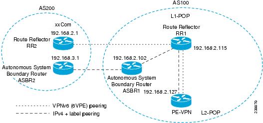
The following additional BGP peerings are necessary to enable interautonomous-system communication from the IPv6 VPN PE located in the Level 2 POP:

  • IPv4 with label peering from the PE VPN to the route reflector named RR1 (which is already configured if VPNv4 interautonomous system is deployed on the same nodes, using the same LSP).
  • IPv4 with label peering from RR1 to ASBR1.
  • IPv4 with label peering between ASBR1 and ASBR2.
  • IPv6 VPN peering between RR1 and RR2 (which is the route reflector in the other autonomous systems) to exchange IPv6 VPN routes.
  • IPv6 VPN peering with RR1. If the same route reflectors used to scale the IPv6 VPN service are used for interautonomous-system capability, then this function might also be already configured (see the Configuring Route Reflectors for Improved Scalability).

Configuring the multiautonomous-system backbone for IPv6 VPN consists of the following tasks:

Configuring the PE VPN for a Multiautonomous-System Backbone

Configuring iBGP IPv6 VPN Peering to a Route Reflector

Perform this task to configure iBGP IPv6 VPN peering to a route reflector named RR1.

SUMMARY STEPS

1.    enable

2.    configure terminal

3.    router bgp autonomous-system-number

4.    neighbor {ip-address | ipv6-address | peer-group-name} remote-as as-number

5.    neighbor {ip-address | ipv6-address | peer-group-name} update-source interface-type interface-number

6.    address-family vpnv6 [unicast]

7.    neighbor {ip-address | peer-group-name | ipv6-address} activate

8.    neighbor {ip-address | ipv6-address | peer-group-name} send-community [both | standard | extended]

9.    exit


DETAILED STEPS
 Command or ActionPurpose
Step 1
enable


Example:

Device> enable


Enables privileged EXEC mode.

  • Enter your password if prompted.
 
Step 2
configure terminal


Example:

Device# configure terminal


Enters global configuration mode.

 
Step 3
router bgp autonomous-system-number


Example:

Device(config)# router bgp 100


Configures the BGP routing process.

 
Step 4
neighbor {ip-address | ipv6-address | peer-group-name} remote-as as-number


Example:

Device(config-router)# neighbor 192.168.2.115 remote-as 100


Adds an entry to the multiprotocol BGP neighbor table for peering with the route reflector with interautonomous-system functionality.

 
Step 5
neighbor {ip-address | ipv6-address | peer-group-name} update-source interface-type interface-number


Example:

Device(config-router)# neighbor 192.168.2.115 update-source Loopback 0


Enables the BGP session to use a source address on the specified interface.

 
Step 6
address-family vpnv6 [unicast]


Example:

Device(config-router)# address-family vpnv6


(Optional) Places the device in address family configuration mode for configuring routing sessions.

 
Step 7
neighbor {ip-address | peer-group-name | ipv6-address} activate


Example:

Device(config-router-af)# neighbor 192.168.2.115 activate


Enables the exchange of information for this address family with the specified BGP neighbor.

 
Step 8
neighbor {ip-address | ipv6-address | peer-group-name} send-community [both | standard | extended]


Example:

Device(config-router-af)# neighbor 192.168.2.115 send-community extended


Specifies that a communities attribute should be sent to the BGP neighbor.

 
Step 9
exit


Example:

Device(config-router-af)# exit


Exits address family configuration mode.

 
Configuring IPv4 and Label iBGP Peering to a Route Reflector

Perform this task to configure IPv4 and label iBGP peering to a route reflector named RR1.

SUMMARY STEPS

1.    enable

2.    configure terminal

3.    router bgp autonomous-system-number

4.    address-family ipv4 [mdt | multicast | tunnel | unicast [vrf vrf-name] | vrf vrf-name]

5.    neighbor {ip-address | peer-group-name | ipv6-address} activate

6.    neighbor { ip-address | ipv6-address | peer-group-name} send-label


DETAILED STEPS
 Command or ActionPurpose
Step 1
enable


Example:

Device> enable


Enables privileged EXEC mode.

  • Enter your password if prompted.
 
Step 2
configure terminal


Example:

Device# configure terminal


Enters global configuration mode.

 
Step 3
router bgp autonomous-system-number


Example:

Device(config)# router bgp 100


Configures the BGP routing process.

 
Step 4
address-family ipv4 [mdt | multicast | tunnel | unicast [vrf vrf-name] | vrf vrf-name]


Example:

Device(config-router)# address-family ipv4


Enters address family configuration mode to configure a routing session using standard IPv4 address prefixes.

 
Step 5
neighbor {ip-address | peer-group-name | ipv6-address} activate


Example:

Device(config-router-af)# neighbor 192.168.2.115 activate


Enables the exchange of information for this address family with the specified BGP neighbor.

 
Step 6
neighbor { ip-address | ipv6-address | peer-group-name} send-label


Example:

Device(config-router-af)# neighbor 192.168.2.115 send-label


Enables label exchange for this address family to this neighbor in order to receive remote PE peer IPv4 loopback with label via RR1 in order to set up an end-to-end LSP.


Configuring the Route Reflector for a Multiautonomous-System Backbone

Configuring Peering to the PE VPN
SUMMARY STEPS

1.    enable

2.    configure terminal

3.    router bgp autonomous-system-number

4.    neighbor {ip-address | ipv6-address | peer-group-name} remote-as as-number

5.    neighbor {ip-address | ipv6-address | peer-group-name} update-source interface-type interface-number

6.    address-family vpnv6 [unicast]

7.    neighbor {ip-address | peer-group-name | ipv6-address} activate

8.    neighbor {ip-address | ipv6-address | peer-group-name} send-community [both | standard | extended]

9.    exit

10.    address-family ipv4 [mdt | multicast | tunnel | unicast [vrf vrf-name] | vrf vrf-name]

11.    neighbor {ip-address | peer-group-name | ipv6-address} activate

12.    neighbor { ip-address | ipv6-address | peer-group-name} send-label

13.    exit


DETAILED STEPS
 Command or ActionPurpose
Step 1
enable


Example:

Device> enable


Enables privileged EXEC mode.

  • Enter your password if prompted.
 
Step 2
configure terminal


Example:

Device# configure terminal


Enters global configuration mode.

 
Step 3
router bgp autonomous-system-number


Example:

Device(config)# router bgp 100


Configures the BGP routing process.

 
Step 4
neighbor {ip-address | ipv6-address | peer-group-name} remote-as as-number


Example:

Device(config-router)# neighbor 192.168.2.115 remote-as 100


Adds an entry to the multiprotocol BGP neighbor table for peering with the route reflector for interautonomous system.

 
Step 5
neighbor {ip-address | ipv6-address | peer-group-name} update-source interface-type interface-number


Example:

Device(config-router)# neighbor 192.168.2.115 update-source Loopback 0


Enables the BGP session to use a source address on the specified interface.

 
Step 6
address-family vpnv6 [unicast]


Example:

Device(config-router)# address-family vpnv6


(Optional) Places the device in address family configuration mode.

 
Step 7
neighbor {ip-address | peer-group-name | ipv6-address} activate


Example:

Device(config-router-af)# neighbor 192.168.2.115 activate


Enables the exchange of information for this address family with the specified BGP neighbor.

 
Step 8
neighbor {ip-address | ipv6-address | peer-group-name} send-community [both | standard | extended]


Example:

Device(config-router-af)# neighbor 192.168.2.115 send-community extended


Specifies that a community attribute should be sent to the BGP neighbor.

 
Step 9
exit


Example:

Device(config-router-af)# exit


Exits address family configuration mode.

 
Step 10
address-family ipv4 [mdt | multicast | tunnel | unicast [vrf vrf-name] | vrf vrf-name]


Example:

Device(config-router)# address-family ipv4


Enters address family configuration mode to configure a routing session using standard IPv4 address prefixes.

 
Step 11
neighbor {ip-address | peer-group-name | ipv6-address} activate


Example:

Device(config-router-af)# neighbor 192.168.2.115 activate


Enables the exchange of information for this address family with the specified BGP neighbor.

 
Step 12
neighbor { ip-address | ipv6-address | peer-group-name} send-label


Example:

Device(config-router-af)# neighbor 192.168.2.115 send-label


Enables label exchange for this address family to this neighbor in order to send to the local PE the remote PE IPv4 loopback with a label in order to set up an end-to-end LSP.

 
Step 13
exit


Example:

Device(config-router-af)# exit


Exits address family configuration mode.

 
Configuring the Route Reflector
SUMMARY STEPS

1.    enable

2.    configure terminal

3.    router bgp autonomous-system-number

4.    neighbor {ip-address | ipv6-address | peer-group-name} remote-as as-number

5.    neighbor {ip-address | ipv6-address | peer-group-name} update-source interface-type interface-number

6.    address-family vpnv6 [unicast]

7.    neighbor {ip-address | peer-group-name | ipv6-address} activate

8.    neighbor {ip-address | ipv6-address | peer-group-name} send-community [both | standard | extended]

9.    neighbor { ip-address | ipv6-address | peer-group-name} route-reflector-client

10.    exit

11.    address-family ipv4 [mdt | multicast | tunnel | unicast [vrf vrf-name] | vrf vrf-name]

12.    neighbor {ip-address | peer-group-name | ipv6-address} activate

13.    neighbor { ip-address | ipv6-address | peer-group-name} send-label

14.    exit


DETAILED STEPS
 Command or ActionPurpose
Step 1
enable


Example:

Device> enable


Enables privileged EXEC mode.

  • Enter your password if prompted.
 
Step 2
configure terminal


Example:

Device# configure terminal


Enters global configuration mode.

 
Step 3
router bgp autonomous-system-number


Example:

Device(config)# router bgp 100


Configures the BGP routing process.

 
Step 4
neighbor {ip-address | ipv6-address | peer-group-name} remote-as as-number


Example:

Device(config-router)# neighbor 192.168.2.127 remote-as 100


Adds an entry to the multiprotocol BGP neighbor table for peering with the VPN PE for interautonomous system.

 
Step 5
neighbor {ip-address | ipv6-address | peer-group-name} update-source interface-type interface-number


Example:

Device(config-router)# neighbor 192.168.2.127 update-source Loopback 0


Enables the BGP session to use a source address on the specified interface.

 
Step 6
address-family vpnv6 [unicast]


Example:

Device(config-router)# address-family vpnv6


(Optional) Places the device in address family configuration mode.

 
Step 7
neighbor {ip-address | peer-group-name | ipv6-address} activate


Example:

Device(config-router-af)# neighbor 192.168.2.127 activate


Enables the exchange of information for this address family with the specified neighbor.

 
Step 8
neighbor {ip-address | ipv6-address | peer-group-name} send-community [both | standard | extended]


Example:

Device(config-router-af)# neighbor 192.168.2.127 send-community extended


Specifies that a community attribute should be sent to the BGP neighbor.

 
Step 9
neighbor { ip-address | ipv6-address | peer-group-name} route-reflector-client


Example:

Device(config-router-af)# neighbor 192.168.2.127 route-reflector-client


Configures the specified neighbor as a route reflector client.

 
Step 10
exit


Example:

Device(config-router-af)# exit


Exits address family configuration mode.

 
Step 11
address-family ipv4 [mdt | multicast | tunnel | unicast [vrf vrf-name] | vrf vrf-name]


Example:

Device(config-router)# address-family ipv4


Enters address family configuration mode to configure a routing session using standard IPv4 address prefixes.

 
Step 12
neighbor {ip-address | peer-group-name | ipv6-address} activate


Example:

Device(config-router-af)# neighbor 192.168.2.127 activate


Enables the exchange of information for this address family with the specified neighbor.

 
Step 13
neighbor { ip-address | ipv6-address | peer-group-name} send-label


Example:

Device(config-router-af)# neighbor 192.168.2.127 send-label


Enables label exchange for this address family to this neighbor in order to send to the local PE the remote PE IPv4 loopback with a label in order to set up an end-to-end LSP.

 
Step 14
exit


Example:

Device(config-router-af)# exit


Exits address family configuration mode.

 
Configuring Peering to the Autonomous System Boundary Router
SUMMARY STEPS

1.    enable

2.    configure terminal

3.    router bgp autonomous-system-number

4.    neighbor {ip-address | ipv6-address | peer-group-name} remote-as as-number

5.    neighbor {ip-address | ipv6-address | peer-group-name} update-source interface-type interface-number

6.    address-family ipv4 [mdt | multicast | tunnel | unicast [vrf vrf-name] | vrf vrf-name]

7.    neighbor {ip-address | peer-group-name | ipv6-address} activate

8.    neighbor { ip-address | ipv6-address | peer-group-name} send-label

9.    exit


DETAILED STEPS
 Command or ActionPurpose
Step 1
enable


Example:

Device> enable


Enables privileged EXEC mode.

  • Enter your password if prompted.
 
Step 2
configure terminal


Example:

Device# configure terminal


Enters global configuration mode.

 
Step 3
router bgp autonomous-system-number


Example:

Device(config)# router bgp 100


Configures the BGP routing process.

 
Step 4
neighbor {ip-address | ipv6-address | peer-group-name} remote-as as-number


Example:

Device(config-router)# neighbor 192.168.2.102 remote-as 100


Adds an entry to the multiprotocol BGP neighbor table for peering with the ASBR1.

 
Step 5
neighbor {ip-address | ipv6-address | peer-group-name} update-source interface-type interface-number


Example:

Device(config-router)# neighbor 192.168.2.102 update-source Loopback 0


Enables the BGP session to use a source address on the specified interface.

 
Step 6
address-family ipv4 [mdt | multicast | tunnel | unicast [vrf vrf-name] | vrf vrf-name]


Example:

Device(config-router)# address-family ipv4


Enters address family configuration mode to configure a routing session using standard IPv4 address prefixes.

 
Step 7
neighbor {ip-address | peer-group-name | ipv6-address} activate


Example:

Device(config-router-af)# neighbor 192.168.2.102 activate


Enables the exchange of information for this address family with the specified BGP neighbor.

 
Step 8
neighbor { ip-address | ipv6-address | peer-group-name} send-label


Example:

Device(config-router-af)# neighbor 192.168.2.102 send-label


Enables label exchange for this address family to this neighbor in order to receive the remote PE IPv4 loopback with the label set to an end-to-end LSP.

 
Step 9
exit


Example:

Device(config-router-af)# exit


Exits address family configuration mode.

 
Configuring Peering to Another ISP Route Reflector

Perform this task to configure peering to an ISP route reflector named RR2.

SUMMARY STEPS

1.    enable

2.    configure terminal

3.    router bgp autonomous-system-number

4.    neighbor {ip-address | ipv6-address | peer-group-name} remote-as as-number

5.    neighbor {ip-address | ipv6-address | peer-group-name} update-source interface-type interface-number

6.    neighbor {ip-address | ipv6-address| peer-group-name} ebgp-multihop [ttl]

7.    address-family vpnv6 [unicast]

8.    neighbor {ip-address | peer-group-name | ipv6-address} activate

9.    neighbor {ip-address | ipv6-address | peer-group-name} send-community [both | standard | extended]

10.    neighbor {ip-address | ipv6-address | peer-group-name} next-hop-unchanged [allpaths]


DETAILED STEPS
 Command or ActionPurpose
Step 1
enable


Example:

Device> enable


Enables privileged EXEC mode.

  • Enter your password if prompted.
 
Step 2
configure terminal


Example:

Device# configure terminal


Enters global configuration mode.

 
Step 3
router bgp autonomous-system-number


Example:

Device(config)# router bgp 100


Configures the BGP routing process.

 
Step 4
neighbor {ip-address | ipv6-address | peer-group-name} remote-as as-number


Example:

Device(config-router)# neighbor 192.168.2.1 remote-as 100


Adds an entry to the multiprotocol BGP neighbor table for eBGP peering with RR2.

 
Step 5
neighbor {ip-address | ipv6-address | peer-group-name} update-source interface-type interface-number


Example:

Device(config-router)# neighbor 192.168.2.1 update-source Loopback 0


Enables the BGP session to use a source address on the specified interface.

 
Step 6
neighbor {ip-address | ipv6-address| peer-group-name} ebgp-multihop [ttl]


Example:

Device(config-router)# neighbor 192.168.2.1 ebgp-multihop


(Optional) Accepts and attempts BGP connections to external peers residing on networks that are not directly connected.

 
Step 7
address-family vpnv6 [unicast]


Example:

Device(config-router)# address-family vpnv6


(Optional) Places the device in address family configuration mode for configuring routing sessions.

 
Step 8
neighbor {ip-address | peer-group-name | ipv6-address} activate


Example:

Device(config-router-af)# neighbor 192.168.2.1 activate


Enables the exchange of information for this address family with the specified BGP neighbor.

 
Step 9
neighbor {ip-address | ipv6-address | peer-group-name} send-community [both | standard | extended]


Example:

Device(config-router-af)# neighbor 192.168.2.1 send-community extended


Specifies that a communities attribute should be sent to the BGP neighbor.

 
Step 10
neighbor {ip-address | ipv6-address | peer-group-name} next-hop-unchanged [allpaths]


Example:

Device(config-router-af)# neighbor 192.168.2.1 next-hop-unchanged allpaths


Enables an eBGP multihop peer to propagate to the next hop unchanged for paths.


Configuring the ASBR

Perform this task to configure peering to an ISP route reflector named RR2.

Configuring Peering with Router Reflector RR1

Perform this task to configure peering with a route reflector named RR1.

SUMMARY STEPS

1.    enable

2.    configure terminal

3.    router bgp autonomous-system-number

4.    neighbor {ip-address | ipv6-address | peer-group-name} remote-as as-number

5.    neighbor {ip-address | ipv6-address | peer-group-name} update-source interface-type interface-number

6.    address-family ipv4 [mdt | multicast | tunnel | unicast [vrf vrf-name] | vrf vrf-name

7.    neighbor {ip-address | peer-group-name | ipv6-address} activate

8.    neighbor ip-address | ipv6-address | peer-group-name send-label

9.    exit


DETAILED STEPS
 Command or ActionPurpose
Step 1
enable


Example:

Device> enable


Enables privileged EXEC mode.

  • Enter your password if prompted.
 
Step 2
configure terminal


Example:

Device# configure terminal


Enters global configuration mode.

 
Step 3
router bgp autonomous-system-number


Example:

Device(config)# router bgp 100


Configures the BGP routing process.

 
Step 4
neighbor {ip-address | ipv6-address | peer-group-name} remote-as as-number


Example:

Device(config-router)# neighbor 192.168.2.115 remote-as 100


Adds an entry to the multiprotocol BGP neighbor table for peering with RR1.

 
Step 5
neighbor {ip-address | ipv6-address | peer-group-name} update-source interface-type interface-number


Example:

Device(config-router)# neighbor 192.168.2.115 update-source Loopback 0


Enables the BGP session to use a source address on the specified interface.

 
Step 6
address-family ipv4 [mdt | multicast | tunnel | unicast [vrf vrf-name] | vrf vrf-name


Example:

Device(config-router)# address-family ipv4


Enters address family configuration mode to configure a routing session using standard IPv4 address prefixes.

 
Step 7
neighbor {ip-address | peer-group-name | ipv6-address} activate


Example:

Device(config-router-af)# neighbor 192.168.2.115 activate


Enables the exchange of information for this address family with the specified BGP neighbor.

 
Step 8
neighbor ip-address | ipv6-address | peer-group-name send-label


Example:

Device(config-router-af)# neighbor 192.168.2.115 send-label


Enables label exchange for this address family to this neighbor in order to send to the local PE the remote PE IPv4 loopback with a label in order to set up an end-to-end LSP.

 
Step 9
exit

Example:

Device(config-router-af)# exit


Exits address family configuration mode.

 
Configuring Peering with the Other ISP ASBR2

Perform this task to configure peering with ASBR2.

SUMMARY STEPS

1.    enable

2.    configure terminal

3.    router bgp autonomous-system-number

4.    neighbor {ip-address | ipv6-address | peer-group-name} remote-as as-number

5.    neighbor {ip-address | ipv6-address | peer-group-name} update-source interface-type interface-number

6.    neighbor {ip-address | ipv6-address| peer-group-name} ebgp-multihop [ttl]

7.    address-family ipv4 [mdt | multicast | tunnel | unicast [vrf vrf-name] | vrf vrf-name]

8.    neighbor {ip-address | peer-group-name | ipv6-address} activate

9.    neighbor { ip-address | ipv6-address | peer-group-name} send-label

10.    network {network-number [mask network-mask] | nsap-prefix} [route-map map-tag]

11.    network {network-number [mask network-mask] | nsap-prefix} [route-map map-tag]


DETAILED STEPS
 Command or ActionPurpose
Step 1
enable


Example:

Device> enable


Enables privileged EXEC mode.

  • Enter your password if prompted.
 
Step 2
configure terminal


Example:

Device# configure terminal


Enters global configuration mode.

 
Step 3
router bgp autonomous-system-number


Example:

Device(config)# router bgp 100


Configures the BGP routing process.

 
Step 4
neighbor {ip-address | ipv6-address | peer-group-name} remote-as as-number


Example:

Device(config-router)# neighbor 192.168.3.1 remote-as 100


Adds an entry to the multiprotocol BGP neighbor table for peering with the ASBR2.

 
Step 5
neighbor {ip-address | ipv6-address | peer-group-name} update-source interface-type interface-number


Example:

Device(config-router)# neighbor 192.168.3.1 update-source Loopback 0


Enables the BGP session to use a source address on the specified interface.

 
Step 6
neighbor {ip-address | ipv6-address| peer-group-name} ebgp-multihop [ttl]


Example:

Device(config-router)# neighbor 192.168.3.1 ebgp-multihop


Accepts and attempts BGP connections to external peers residing on networks that are not directly connected.

 
Step 7
address-family ipv4 [mdt | multicast | tunnel | unicast [vrf vrf-name] | vrf vrf-name]


Example:

Device(config-router)# address-family ipv4


Enters address family configuration mode to configure a routing session using standard IPv4 address prefixes.

 
Step 8
neighbor {ip-address | peer-group-name | ipv6-address} activate


Example:

Device(config-router-af)# neighbor 192.168.3.1 activate


Enables the exchange of information for this address family with the specified BGP neighbor.

 
Step 9
neighbor { ip-address | ipv6-address | peer-group-name} send-label


Example:

Device(config-router-af)# neighbor 192.168.3.1 send-label


Enables label exchange for this address family to this neighbor in order to receive the remote PE IPv4 loopback with a label in order to set up an end-to-end LSP.

 
Step 10
network {network-number [mask network-mask] | nsap-prefix} [route-map map-tag]


Example:

Device(config-router-af)# network 192.168.2.27 mask 255.255.255.255


Flags a network as local to this autonomous system and enters the network to the BGP table. This configuration is for the PE VPN loopback.

 
Step 11
network {network-number [mask network-mask] | nsap-prefix} [route-map map-tag]


Example:

Device(config-router-af)# network 192.168.2.15 mask 255.255.255.255


Flags a network as local to this autonomous system and enters the network to the BGP table. This configuration is for the RR1 loopback.


Configuring CSC for IPv6 VPN

Perform this task to configure CsC-PE1 peering configuration with CsC-CE1.

SUMMARY STEPS

1.    enable

2.    configure terminal

3.    hostname name

4.    router bgp autonomous-system-number

5.    address-family ipv6 [vrf vrf-name] [unicast | multicast]

6.    neighbor {ip-address | ipv6-address | peer-group-name} remote-as as-number

7.    neighbor {ip-address | peer-group-name | ipv6-address} activate

8.    neighbor { ip-address | ipv6-address | peer-group-name} send-label


DETAILED STEPS
 Command or ActionPurpose
Step 1
enable


Example:

Device> enable


Enables privileged EXEC mode.

  • Enter your password if prompted.
 
Step 2
configure terminal


Example:

Device# configure terminal


Enters global configuration mode.

 
Step 3
hostname name


Example:

Device(config)# hostname CSC-PE1


Specifies or modifies the host name for the network server.

 
Step 4
router bgp autonomous-system-number


Example:

Device(config)# router bgp 100


Configures the BGP routing process.

 
Step 5
address-family ipv6 [vrf vrf-name] [unicast | multicast]


Example:

Device(config-router)# address-family ipv6 vrf ISP2


Enters address family configuration mode.

 
Step 6
neighbor {ip-address | ipv6-address | peer-group-name} remote-as as-number


Example:

Device(config-router-af)# neighbor FE80::866C:99 Serial0/0 remote-as 200


Adds an entry to the multiprotocol BGP neighbor table.

 
Step 7
neighbor {ip-address | peer-group-name | ipv6-address} activate


Example:

Device(config-router-af)# neighbor FE80::866C:99 Serial0/0 activate


Enables the exchange of information for this address family with the specified BGP neighbor.

 
Step 8
neighbor { ip-address | ipv6-address | peer-group-name} send-label


Example:

Device(config-router-af)# neighbor FE80::866C:99 Serial0/0 send-label


Enables label exchange for this address family to this neighbor.


Configuration Examples for IPv6 VPN over MPLS

IPv6 VPN over MPLS Routing Examples

Example: BGP IPv6 Activity Summary

Device# show bgp ipv6 summary
 
For address family: IPv6 Unicast
BGP router identifier 192.168.2.126, local AS number 33751
BGP table version is 15, main routing table version 15
12 network entries using 1692 bytes of memory
22 path entries using 1672 bytes of memory
5/4 BGP path/bestpath attribute entries using 580 bytes of memory
14 BGP rrinfo entries using 336 bytes of memory
2 BGP AS-PATH entries using 48 bytes of memory
0 BGP route-map cache entries using 0 bytes of memory
0 BGP filter-list cache entries using 0 bytes of memory
BGP using 4328 total bytes of memory
Dampening enabled. 0 history paths, 0 dampened paths
BGP activity 13/1 prefixes, 23/1 paths, scan interval 60 secs
Neighbor        V    AS MsgRcvd MsgSent   TblVer  InQ OutQ Up/Down  State/PfxRcd
192.168.2.146     4 33751     991     983       15    0    0 16:26:21       10
192.168.2.147     4 33751     991     983       15    0    0 16:26:22       10
FE80::4F6B:44%Serial1/0
                4 20331     982     987       15    0    0 14:55:52        1

Example: Dumping the BGP IPv6 Tables

Each table (for example, BGP IPv6, BGP IPv6 VPN) can be reviewed individually, as shown in the following example:

Device# show bgp ipv6 unicast 
BGP table version is 15, local router ID is 192.168.2.126
Status codes: s suppressed, d damped, h history, * valid, > best, i - internal,
              r RIB-failure, S Stale
Origin codes: i - IGP, e - EGP, ? - incomplete
   Network          Next Hop            Metric    LocPrf Weight Path
* i2001:DB8:100::/48 ::FFFF:192.168.2.101     0    100      0 10000 ?
*>i                  ::FFFF:192.168.2.101     0    100      0 10000 ?
* i2001:DB8::1/128   ::FFFF:192.168.2.101     0    100      0  i
*>i                  ::FFFF:192.168.2.101     0    100      0  i

Example: Dumping the IPv6 Routing Tables

IPv6 routing tables identify each routing protocol contributor to routable entries, as shown in the following example:

Device# show ipv6 route
IPv6 Routing Table - default - 13 entries
Codes: C - Connected, L - Local, S - Static, U - Per-user Static route
       B - BGP, R - RIP, I1 - ISIS L1, I2 - ISIS L2
       IA - ISIS interarea, IS - ISIS summary
       O - OSPF Intra, OI - OSPF Inter, OE1 - OSPF ext 1, OE2 - OSPF ext 2
       ON1 - OSPF NSSA ext 1, ON2 - OSPF NSSA ext 2
B   2001:DB8:100::/48 [200/0]
     via 192.168.2.101 Default-IP-Routing-Table, indirectly connected
B   2001:DB8::1/128 [200/0]
     via 192.168.2.101 Default-IP-Routing-Table, c
LC  2001:DB8::26/128 [0/0]
     via Loopback0, receive

From an IPv6 routing perspective, entries reachable over the MPLS backbone are listed as being indirectly connected, because MPLS is providing a Layer 2 tunnel mechanism.

IPv6 VPN over MPLS Forwarding Examples

Example: PE-CE Connectivity

The ipv6 ping and traceroute commands are useful to check connectivity from a PE to a CE, whether locally attached or remote over the MPLS backbone.

When a device is locally attached, one can use the ipv6 ping command with the CE link-local address (used for eBGP peering), as shown in the following example:

Device# ping FE80::4F6B:44%Serial1/0
 
Type escape sequence to abort.
Sending 5, 100-byte ICMP Echos to FE80::4F6B:44, timeout is 2 seconds:
!!!!!
Success rate is 100 percent (5/5), round-trip min/avg/max = 28/33/48 ms

The ipv6 ping command also can be used to test remote PE or CE reachability, but only IPv6 global addresses can be used (link-local addresses are not advertised beyond the link):

Device# ping 2001:DB8:1120:1::44
Type escape sequence to abort.
Sending 5, 100-byte ICMP Echos to 2001:DB8:1120:1:44::1, timeout is 2 seconds:
!!!!!
Success rate is 100 percent (5/5), round-trip min/avg/max = 28/33/48 ms

The ping ipv6 and traceroute command functions over MPLS require PEs and CEs to announce one IPv6 global prefix. Each 6PE device announces 2001:DB8::PE#/128, filtered at the autonomous system edge. Each IPv6 CE configures 2001:DB8:prefix:CE#/128 and announces it as part as its less-specific prefix (2001:DB8:prefix::/n).

Reachability of remote PEs and CEs can be tested by using the traceroute command. If you have configured all PEs with the no mpls ip propagate-ttl forwarded command, when the traceroute command is executed from a CE, its output will show only the IPv6 nodes:

Device# traceroute 2001:DB8::1
Type escape sequence to abort.
Tracing the route to 2001:DB8::1
  1 2001:DB8::26 [AS 33751] 32 msec 32 msec 20 msec
  2 2001:DB8::1 [AS 33751] [MPLS: Label 73 Exp 0] 20 msec 20 msec 20 msec
  3 2001:DB8::1 [AS 33751] 28 msec 20 msec 20 msec

After the P devices have been upgraded with images that support ICMPv6, the traceroute command executed on the PE device (Time to Live [TTL] is then propagated) will also show P devices' responses, as shown in the following example:

Device# traceroute 2001:DB8::1
 
Type escape sequence to abort.
Tracing the route to 2001:DB8::1
  1 ::FFFF:172.20.25.1 [MPLS: Labels 38/73 Exp 0] 40 msec 32 msec 32 msec
  2 ::FFFF:172.20.10.1 [MPLS: Labels 30/73 Exp 0] 60 msec 32 msec 32 msec
  3 2001:DB8::1 [MPLS: Label 73 Exp 0] 32 msec 32 msec 16 msec

When run from a 6VPE device, both the ping ipv6 and traceroute commands accept a vrf argument, exactly as in the case of VPNv4.

The traceroute command is useful for evaluating the path across the MPLS backbone, but not for troubleshooting data-plane failures. The P devices are IPv6 unaware (and are also VPNv4 unaware), so the ICMPv6 messages that they generate in response to the traceroute command are forwarded to the egress PE using the received label stack. The egress PE can route the ICMPv6 message to the source of the traceroute. When the MPLS path is broken, it is also broken from the ICMP message, which cannot reach the egress PE.

Example: PE Imposition Path

On Cisco devices, the most useful tool for troubleshooting the imposition path for IPv6 is the show ipv6 cef command.

Dumping IPv6 Forwarding Table

You can use the show ipv6 cef command to display the forwarding table with label stacks used for each destination prefix, as shown in the following example:

Device# show ipv6 cef
 
2001:DB8:100::/48
  nexthop 172.20.25.1 Serial0/0 label 38 72
2001:DB8::1/128
  nexthop 172.20.25.1 Serial0/0 label 38 73
2001:DB8::26/128
  attached to Loopback0, receive
Details of an IPv6 Entry in the Forwarding Table

You can use the show ipv6 cef command to display details for a specific entry and to analyze how the destination was resolved and the label stack computed, as shown in the following example:

Device# show ipv6 cef 2001:DB8:100::/48 internal
2001:DB8:100::/48, epoch 0, RIB[B], refcount 4
  sources: RIB 
..
  recursive via 192.168.2.101[IPv4:Default] label 72, fib 0252B1F8, 1 terminal fib
    path 024F56A8, path list 024F0BA8, share 0/1, type attached nexthop
    ifnums: (none)
     path_list contains at least one resolved destination(s). HW IPv4 notified.
    nexthop 172.20.25.1 Serial0/0 label 38, adjacency IP adj out of Serial0/0 0289BEF0
  output chain: label 72 label 38 TAG adj out of Serial0/0 0289BD80
Details of a BGP Entry in the BGP Table

The detailed output in the previous example shows that each label composing the label stack has a different origin that can be tracked down individually. The BGP table has the bottom label, as shown in the following example:

Device# show bgp ipv6 unicast 2001:DB8:100::/48
 
BGP routing table entry for 2001:DB8:100::/48, version 2
Paths: (2 available, best #2, table default)
  Advertised to update-groups:
     1         
  10000
    ::FFFF:192.168.2.101 (metric 30) from 192.168.2.147 (192.168.2.147)
      Origin incomplete, metric 0, localpref 100, valid, internal
      Originator: 192.168.2.101, Cluster list: 192.168.2.147,
      mpls labels in/out nolabel/72
  10000
    ::FFFF:192.168.2.101 (metric 30) from 192.168.2.146 (192.168.2.146)
      Origin incomplete, metric 0, localpref 100, valid, internal, best
      Originator: 192.168.2.101, Cluster list: 192.168.2.146,
      mpls labels in/out nolabel/72

LDP displays the other labels:

Device# show mpls ldp bindings 192.168.2.101 32
  lib entry: 192.168.2.101/32, rev 56
        local binding:  label: 40
        remote binding: lsr: 192.168.2.119:0, label: 38
Device# show mpls ldp bindings 172.20.25.0 24
  lib entry: 172.20.25.0/24, rev 2
        local binding: label: imp-null
        remote binding: lsr: 192.168.2.119:0, label: imp-null

Example: PE Disposition Path

Use the following examples to troubleshoot the disposition path.

Dumping the MPLS Forwarding Table

The following example illustrates MPLS forwarding table information for troubleshooting the disposition path.

Device# show mpls forwarding-table 
Local  Outgoing      Prefix            Bytes Label   Outgoing   Next Hop    
Label  Label or VC   or Tunnel Id      Switched      interface              
16     Pop Label     192.168.2.114/32    0             Se0/0      point2point 
17     26            192.168.2.146/32    0             Se0/0      point2point 
..
72     No Label      2001:DB8:100::/48     63121         Se1/0      point2point 
73     Aggregate     2001:DB8::1/128   24123 
BGP Label Analysis

The following example illustrates the label used for switching, which has been announced by iBGP (6PE in this example) and can be checked:

Device# show bgp ipv6 2001:DB8:100::/48
              
BGP routing table entry for 2001:DB8:100::/48, version 2
Paths: (1 available, best #1, table default)
  Advertised to update-groups:
     2         
  10000
    FE80::2710:2 (FE80::2710:2) from FE80::2710:2%Serial1/0 (192.168.2.103)
      Origin incomplete, metric 0, localpref 100, valid, external, best,

Example: Label Switch Path

Because the 6PE and 6VPE LSP endpoints are IPv4 addresses, the IPv4 tools for troubleshooting LSPs are useful for detecting data-plane failures that would lead to IPv6 traffic black-holing.

Analyzing the Label Switch Path

The following example displays the LSP IPv4 end:

Device# show ipv6 route 2001:DB8::1/128
Routing entry for 2001:DB8::1/128
  Known via "bgp 33751", distance 200, metric 0, type internal
  Route count is 1/1, share count 0
  Routing paths:
    192.168.2.101%Default-IP-Routing-Table indirectly connected
      MPLS Required
      Last updated 02:42:12 ago
Traceroute LSP Example

The following example shows the traceroute LSP:

Device# traceroute mpls ipv4 192.168.2.101/32 verbose
 
Tracing MPLS Label Switched Path to 192.168.2.101/32, timeout is 2 seconds
Codes: '!' - success, 'Q' - request not transmitted,
       '.' - timeout, 'U' - unreachable,
       'R' - downstream router but not target,
       'M' - malformed request
Type escape sequence to abort.
  0 172.20.25.2 0.0.0.0 MRU 1500 [Labels: 38 Exp: 0]
R 1 172.20.25.1 0.0.0.0 MRU 1500 [Labels: 30 Exp: 0] 40 ms, ret code 6
R 2 172.20.10.1 0.0.0.0 MRU 1504 [Labels: implicit-null Exp: 0] 60 ms, ret code 6
! 3 172.20.40.1 48 ms

IPv6 VPN over MPLS VRF Examples

Example: VRF Information

The following entries show VRF information for 6VPE.

show ipv6 cef vrf

The following is sample output from a Cisco Express Forwarding FIB associated with a VRF named cisco1:

Device# show ipv6 cef vrf cisco1 
 2001:8::/64 
  attached to FastEthernet0/0 
 2001:8::3/128 
  receive 
 2002:8::/64 
  nexthop 10.1.1.2 POS4/0 label 22 19 
 2010::/64 
  nexthop 2001:8::1 FastEthernet0/0 
 2012::/64 
  attached to Loopback1 
 2012::1/128 
  receive 
show ipv6 route vrf

The following is sample output regarding an IPv6 routing table associated with a VRF named cisco1:

Device# show ipv6 route vrf cisco1 
IPv6 Routing Table cisco1 - 6 entries
Codes: C - Connected, L - Local, S - Static, R - RIP, B - BGP 
       U - Per-user Static route 
       I1 - ISIS L1, I2 - ISIS L2, IA - ISIS interarea 
       O - OSPF intra, OI - OSPF inter, OE1 - OSPF ext 1, OE2 - OSPF ext 2 
C   2001:8::/64 [0/0] 
     via ::, FastEthernet0/0 
L   2001:8::3/128 [0/0] 
     via ::, FastEthernet0/0 
B   2002:8::/64 [200/0] 
     via ::FFFF:192.168.1.4, 
B   2010::/64 [20/1] 
     via 2001:8::1, 
C   2012::/64 [0/0] 
     via ::, Loopback1 
L   2012::1/128 [0/0] 
     via ::, Loopback1 

Example: IPv6 VPN Configuration Using IPv4 Next Hop

The following example illustrates a 6VPE next hop:

interface Loopback0
 ip address 192.168.2.11 255.255.255.255
! 
router bgp 100
 neighbor 192.168.2.10 remote-as 100
 neighbor 192.168.2.10 update-source Loopback0
!
 address-family vpnv6
 neighbor 192.168.2.10 activate
 neighbor 192.168.2.10 send-community extended
 exit-address-family

By default, the next hop advertised will be the IPv6 VPN address:

[0:0]::FFFF:192.168.2.10

Note that it is a 192-bit address in the format of [RD]::FFFF:IPv4-address.

When the BGP IPv6 VPN peers share a common subnet, the MP_REACH_NLRI attribute contains a link-local address next hop in addition to the global address next hop. This situation typically occurs in an interautonomous-system topology when ASBRs are facing each other. In that case, the link-local next hop is used locally, and the global next hop is readvertised by BGP.

The BGP next hop is the keystone for building the label stack. The inner label is obtained from the BGP NLRI, and the outer label is the label distribution protocol (LDP) label to reach the IPv4 address embedded into the BGP next hop.

Additional References

Related Documents

Related Topic Document Title

IPv6 addressing and connectivity

IPv6 Configuration Guide

Cisco IOS commands

Master Commands List, All Releases

IPv6 commands

IPv6 Command Reference

Cisco IOS IPv6 features

IPv6 Feature Mapping

Configuring MPLS Layer 3 VPNs

"Configuring MPLS Layer 3 VPNs" feature module in the MPLS Layer 3 VPNs Configuration Guide

Standards and RFCs

Standard/RFC Title

RFCs for IPv6

IPv6 RFCs

Technical Assistance

Description Link

The Cisco Support and Documentation website provides online resources to download documentation, software, and tools. Use these resources to install and configure the software and to troubleshoot and resolve technical issues with Cisco products and technologies. Access to most tools on the Cisco Support and Documentation website requires a Cisco.com user ID and password.

http://www.cisco.com/cisco/web/support/index.html

Feature Information for IPv6 VPN over MPLS

The following table provides release information about the feature or features described in this module. This table lists only the software release that introduced support for a given feature in a given software release train. Unless noted otherwise, subsequent releases of that software release train also support that feature.

Use Cisco Feature Navigator to find information about platform support and Cisco software image support. To access Cisco Feature Navigator, go to www.cisco.com/go/cfn. An account on Cisco.com is not required.

Table 1Feature Information for IPv6 VPN over MPLS
Feature Name Releases Feature Information

IPv6 VPN over MPLS (6VPE)

12.2(28)SB

12.2(33)SRB

12.2(33)SXI

12.4(20)T

15.0(1)S

The IPv6 VPN (6VPE) over a MPLS IPv4 core infrastructure feature allows ISPs to offer IPv6 VPN services to their customers.

The following commands were introduced or modified: aggregate-address, address-family ipv6, address-family vpnv6, ipv6 route, mls ipv6 vrf, neighbor activate, neighbor ebgp-multihop, neighbor next-hop-unchanged, neighbor remote-as, neighbor route-reflector-client, neighbor send-community, neighbor send-label, neighbor update-source, network, rd, router bgp, route-target, vrf definition, vrf forwarding.

Glossary

  • 6VPE device --Provider edge device providing BGP-MPLS IPv6 VPN service over an IPv4-based MPLS core. It is a IPv6 VPN PE, dual-stack device that implements 6PE concepts on the core-facing interfaces.
  • customer edge (CE) device --A service provider device that connects to VPN customer sites.
  • Forwarding Information Base (FIB) --Table containing the information necessary to forward IP datagrams. At a minimum, the FIB contains the interface identifier and next-hop information for each reachable destination network prefix.
  • inbound route filtering (IRF) --A BGP capability used for filtering incoming BGP updates that are not to be imported by the receiving PE device.
  • IPv6 provider edge device (6PE device) --Device running a BGP-based mechanism to interconnect IPv6 islands over an MPLS-enabled IPv4 cloud.
  • IPv6 VPN address --A IPv6 VPN address is a 24-byte identifier, beginning with an 8-byte route distinguisher (RD) and ending with a 16-byte IPv6 address. Sometimes it is called an IPv6 VPN address.
  • IPv6 VPN address family --The address-family identifier (AFI) identifies a particular network-layer protocol and the subsequent AFI (SAFI) provides additional information. The AFI IPv6 SAFI VPN (AFI=2, SAFI=128) is called the IPv6 VPN address family. Sometimes it is called the IPv6 VPN address family. Similarly AFI IPv4 SAFI VPN is the VPNv4 address family.
  • network layer reachability information (NLRI) --BGP sends routing update messages containing NLRI to describe a route and how to get there. In this context, an NLRI is a prefix. A BGP update message carries one or more NLRI prefixes and the attributes of a route for the NLRI prefixes; the route attributes include a BGP next hop gateway address and community values.
  • outbound route filtering (ORF) --A BGP capability used to filtering outgoing BGP routing updates.
  • point of presence (POP) --Physical location where an interexchange carrier installed equipment to interconnect with a local exchange carrier.
  • provider edge (PE) device --A service provider device connected to VPN customer sites.
  • route distinguisher (RD) --A 64-bit value prepended to an IPv6 prefix to create a globally unique IPv6 VPN address.
  • Routing Information Base (RIB) --Also called the routing table.
  • Virtual routing and forwarding (VRF) --A VPN routing and forwarding instance in a PE.
  • VRF table --A routing and a forwarding table associated to a VRF. This is a customer-specific table that enables the PE device to maintain independent routing states for each customer.

Cisco and the Cisco logo are trademarks or registered trademarks of Cisco and/or its affiliates in the U.S. and other countries. To view a list of Cisco trademarks, go to this URL: www.cisco.com/go/trademarks. Third-party trademarks mentioned are the property of their respective owners. The use of the word partner does not imply a partnership relationship between Cisco and any other company. (1110R)

Any Internet Protocol (IP) addresses and phone numbers used in this document are not intended to be actual addresses and phone numbers. Any examples, command display output, network topology diagrams, and other figures included in the document are shown for illustrative purposes only. Any use of actual IP addresses or phone numbers in illustrative content is unintentional and coincidental.

© 2012 Cisco Systems, Inc. All rights reserved.