
 Feedback
Contents
- MPLS LSP Ping Traceroute for LDP TE and LSP Ping for VCCV
- Finding Feature Information
- Prerequisites for MPLS LSP Ping Traceroute for LDP TE and LSP Ping for VCCV
- Restrictions for MPLS LSP Ping Traceroute for LDP TE and LSP Ping for VCCV
- Information About MPLS LSP Ping Traceroute for LDP TE and LSP Ping for VCCV
- MPLS LSP Ping Traceroute for LDP TE and LSP Ping for VCCV Functionality
- MPLS LSP Ping Operation
- MPLS LSP Traceroute Operation
- MPLS Network Management with MPLS LSP Ping and MPLS LSP Traceroute
- Any Transport over MPLS Virtual Circuit Connection
- AToM VCCV Signaling
- Selection of AToM VCCV Switching Types
- Information Provided by the Router Processing LSP Ping or LSP Traceroute
- IP Does Not Forward MPLS Echo Request Packets
- Compatibility Between the MPLS LSP and Ping or Traceroute Implementations
- CiscoVendorExtensions
- DSCP Option to Request a Specific Class of Service in an Echo Reply
- Reply Modes for an MPLS LSP Ping and LSP Traceroute Echo Request Response
- IPv4 Reply Mode
- Router-Alert Reply Mode
- LSP Breaks
- How to Configure MPLS LSP Ping Traceroute for LDP TE and LSP Ping for VCCV
- Enabling Compatibility Between the MPLS LSP and Ping or Traceroute Implementation
- Validating an LDP IPv4 FEC by Using MPLS LSP Ping and MPLS LSP Traceroute
- Validating a Layer 2 FEC by Using MPLS LSP Ping and MPLS LSP Traceroute
- Using DSCP to Request a Specific Class of Service in an Echo Reply
- Controlling How a Responding Router Replies to an MPLS Echo Request
- Using MPLS LSP Ping to Discover Possible Loops
- Using MPLS LSP Traceroute to Discover Possible Loops
- Tracking Packets Tagged as Implicit Null
- Tracking Untagged Packets
- Determining Why a Packet Could Not Be Sent
- Detecting LSP Breaks when Load Balancing Is Enabled for IPv4 LDP LSPs
- Specifying the Interface Through Which Echo Packets Leave a Router
- Pacing the Transmission of Packets
- Interrogating the Transit Router for Its Downstream Information by Using Echo Request request-dsmap
- Interrogating a Router for Its DSMAP
- Requesting that a Transit Router Validate the Target FEC Stack
- Enabling LSP Ping to Detect LSP Breakages Caused by Untagged Interfaces
- Viewing the AToM VCCV Capabilities Advertised to and Received from the Peer
- Configuration Examples for MPLS LSP Ping Traceroute for LDP TE and LSP Ping for VCCV
- Enabling Compatibility Between the MPLS LSP and Ping or Traceroute Implementation Example
- Validating an LDP IPv4 FEC by Using MPLS LSP Ping and MPLS LSP Traceroute Example
- Validating a Layer 2 FEC by Using MPLS LSP Ping Example
- Using DSCP to Request a Specific Class of Service in an Echo Reply Example
- Controlling How a Responding Router Replies to an MPLS Echo Request Example
- Preventing Possible Loops with MPLS LSP Ping Example
- Preventing Possible Loops with MPLS LSP Traceroute Example
- Troubleshooting with LSP Ping or Traceroute Example
- Configuration for Sample Topology
- Verification That the LSP Is Configured Correctly
- Discovery of LSP Breaks
- MTU Discovery in an LSP Example
- Tracking Packets Tagged as Implicit Null Example
- Tracking Untagged Packets Example
- Determining Why a Packet Could Not Be Sent Example
- Detecting LSP Breaks when Load Balancing Is Enabled for IPv4 LSPs Example
- Specifying the Interface Through Which Echo Packets Leave a Router Example
- Pacing the Transmission of Packets Example
- Interrogating the Transit Router for Its Downstream Information Example
- Interrogating a Router for Its DSMAP Example
- Requesting that a Transit Router Validate the Target FEC Stack Example
- Enabling LSP Ping to Detect LSP Breakages Caused by Untagged Interfaces Example
- Viewing the AToM VCCV Capabilities Advertised to and Received from the Peer Example
- Additional References
- Feature Information for MPLS LSP Ping Traceroute for LDP TE and LSP Ping for VCCV
- Glossary
MPLS LSP Ping Traceroute for LDP TE and LSP Ping for VCCV
The MPLS LSP Ping/Traceroute for LDP/TE, and LSP Ping for VCCV feature helps service providers monitor label switched paths (LSPs) and quickly isolate Multiprotocol Label Switching (MPLS) forwarding problems.
The feature provides the following capabilities:
- MPLS LSP ping to test LSP connectivity for IPv4 Label Distribution Protocol (LDP) prefixes, Resource Reservation Protocol (RSVP) traffic engineering (TE), and Any Transport over MPLS (AToM) forwarding equivalence classes (FECs).
- MPLS LSP traceroute to trace the LSPs for IPv4 LDP prefixes and RSVP TE prefixes.
- Finding Feature Information
- Prerequisites for MPLS LSP Ping Traceroute for LDP TE and LSP Ping for VCCV
- Restrictions for MPLS LSP Ping Traceroute for LDP TE and LSP Ping for VCCV
- Information About MPLS LSP Ping Traceroute for LDP TE and LSP Ping for VCCV
- How to Configure MPLS LSP Ping Traceroute for LDP TE and LSP Ping for VCCV
- Configuration Examples for MPLS LSP Ping Traceroute for LDP TE and LSP Ping for VCCV
- Additional References
- Feature Information for MPLS LSP Ping Traceroute for LDP TE and LSP Ping for VCCV
- Glossary
Finding Feature Information
Your software release may not support all the features documented in this module. For the latest feature information and caveats, see the release notes for your platform and software release. To find information about the features documented in this module, and to see a list of the releases in which each feature is supported, see the Feature Information Table at the end of this document.
Use Cisco Feature Navigator to find information about platform support and Cisco software image support. To access Cisco Feature Navigator, go to www.cisco.com/go/cfn. An account on Cisco.com is not required.
Prerequisites for MPLS LSP Ping Traceroute for LDP TE and LSP Ping for VCCV
Before you use the MPLS LSP Ping/Traceroute for LDP/TE, and LSP Ping for VCCV feature, you should:
- Determine the baseline behavior of your MPLS network. For example:
- Understand how to use MPLS and MPLS applications. You need to:
- Understand label switching, forwarding, and load balancing.
Before using the ping mpls or trace mpls command, you must ensure that the router is configured to encode and decode MPLS echo packets in a format that all receiving routers in the network can understand.
Restrictions for MPLS LSP Ping Traceroute for LDP TE and LSP Ping for VCCV
- You cannot use MPLS LSP traceroute to trace the path taken by AToM packets. MPLS LSP traceroute is not supported for AToM. (MPLS LSP ping is supported for AToM.) However, you can use MPLS LSP traceroute to troubleshoot the Interior Gateway Protocol (IGP) LSP that is used by AToM.
- You cannot use MPLS LSP ping to validate or trace MPLS Virtual Private Networks (VPNs).
- You cannot use MPLS LSP traceroute to troubleshoot LSPs that employ time-to-live (TTL) hiding.
- MPLS supports per-destination and per-packet (round robin) load balancing. If per-packet load balancing is in effect, you should not use MPLS LSP traceroute because LSP traceroute at a transit router consistency checks the information supplied in the previous echo response from the directly connected upstream router. When round robin is employed, the path that an echo request packet takes cannot be controlled in a way that allows a packet to be directed to TTL expire at a given router. Without that ability, the consistency checking may fail during an LSP traceroute. A consistency check failure return code may be returned.
- A platform must support LSP ping and traceroute in order to respond to an MPLS echo request packet.
- Unless the MPLS LSP Ping/Traceroute for LDP/TE, and LSP Ping for VCCV feature is enabled along the entire path, you cannot get a reply if the request fails along the path at any node.
- There are certain limitations when a mixture of draft versions are implemented within a network. The version of the draft must be compatible with Cisco's implementation. Due to the way the LSP Ping draft was written, earlier versions may not be compatible with later versions because of changes to type, length, values (TLVs) formats without sufficient versioning information. Cisco attempts to compensate for this in its implementations by allowing the sending and responding routers to be configured to encode and decode echo packets assuming a certain version.
- If you want to use MPLS LSP traceroute, the network should not use TTL hiding.
Information About MPLS LSP Ping Traceroute for LDP TE and LSP Ping for VCCV
- MPLS LSP Ping Traceroute for LDP TE and LSP Ping for VCCV Functionality
- MPLS LSP Ping Operation
- MPLS LSP Traceroute Operation
- MPLS Network Management with MPLS LSP Ping and MPLS LSP Traceroute
- Any Transport over MPLS Virtual Circuit Connection
- IP Does Not Forward MPLS Echo Request Packets
- Compatibility Between the MPLS LSP and Ping or Traceroute Implementations
- DSCP Option to Request a Specific Class of Service in an Echo Reply
- Reply Modes for an MPLS LSP Ping and LSP Traceroute Echo Request Response
- LSP Breaks
MPLS LSP Ping Traceroute for LDP TE and LSP Ping for VCCV Functionality
Internet Control Message Protocol (ICMP) ping and traceroute are often used to help diagnose the root cause when a forwarding failure occurs. However, they are not well suited for identifying LSP failures because an ICMP packet can be forwarded via IP to the destination when an LSP breakage occurs.
The MPLS LSP Ping/Traceroute for LDP/TE, and LSP Ping for VCCV feature is well suited for identifying LSP breakages for the following reasons:
- An MPLS echo request packet cannot be forwarded via IP because IP TTL is set to 1 and the IP destination address field is set to a 127/8 address.
- The FEC being checked is not stored in the IP destination address field (as is the case of ICMP).
MPLS echo request and reply packets test LSPs. There are two methods by which a downstream router can receive packets:
- The Cisco implementation of MPLS echo request and echo reply that was previously based on the Internet Engineering Task Force (IETF) Internet Draft Detecting MPLS Data Plane Failures (draft-ietf-mpls-lsp-ping-03.txt).
-
Features described in this document that are based on the IETF RFC 4379
Detecting Multi-Protocol Label Switched (MPLS) Data Plane Failures
:
- Echo request output interface control
- Echo request traffic pacing
- Echo request end-of-stack explicit-null label shimming
- Echo request request-dsmap capability
- Request-fec checking
- Depth limit reporting
MPLS LSP Ping Operation
MPLS LSP ping uses MPLS echo request and reply packets to validate an LSP. You can use MPLS LSP ping to validate IPv4 LDP, AToM, and IPv4 RSVP FECs by using appropriate keywords and arguments with the ping mplscommand.
The MPLS echo request packet is sent to a target router through the use of the appropriate label stack associated with the LSP to be validated. Use of the label stack causes the packet to be forwarded over the LSP itself.
The destination IP address of the MPLS echo request packet is different from the address used to select the label stack. The destination IP address is defined as a 127.x .y .z /8 address. The 127.x .y .z /8 address prevents the IP packet from being IP switched to its destination if the LSP is broken.
An MPLS echo reply is sent in response to an MPLS echo request. The reply is sent as an IP packet and it is forwarded using IP, MPLS, or a combination of both types of switching. The source address of the MPLS echo reply packet is an address obtained from the router generating the echo reply. The destination address is the source address of the router that originated the MPLS echo request packet.
The MPLS echo reply destination port is set to the echo request source port.
The figure below shows MPLS LSP ping echo request and echo reply paths.
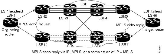
If you initiate an MPLS LSP ping request at LSR1 to a FEC at LSR6, you get the results shown in the table below.
| Table 1 | MPLS LSP Ping Example |
|
Step |
Router |
Action |
|---|---|---|
|
1. |
LSR1 |
Initiates an MPLS LSP ping request for an FEC at the target router LSR6 and sends an MPLS echo request to LSR2. |
|
2. |
LSR2 |
Receives the MPLS echo request packet and forwards it through transit routers LSR3 and LSR4 to the penultimate router LSR5. |
|
3. |
LSR5 |
Receives the MPLS echo request, pops the MPLS label, and forwards the packet to LSR6 as an IP packet. |
|
4. |
LSR6 |
Receives the IP packet, processes the MPLS echo request, and sends an MPLS echo reply to LSR1 through an alternate route. |
|
5. |
LSR7 to LSR10 |
Receives the MPLS echo reply and forwards it back toward LSR1, the originating router. |
|
6. |
LSR1 |
Receives the MPLS echo reply in response to its MPLS echo request. |
MPLS LSP Traceroute Operation
MPLS LSP traceroute uses MPLS echo request and reply packets to validate an LSP. You can use MPLS LSP traceroute to validate IPv4 LDP and IPv4 RSVP FECs by using appropriate keywords and arguments with the trace mpls command.
The MPLS LSP Traceroute feature uses TTL settings to force expiration of the TTL along an LSP. MPLS LSP Traceroute incrementally increases the TTL value in its MPLS echo requests (TTL = 1, 2, 3, 4) to discover the downstream mapping of each successive hop. The success of the LSP traceroute depends on the transit router processing the MPLS echo request when it receives a labeled packet with a TTL = 1. On Cisco routers, when the TTL expires, the packet is sent to the Route Processor (RP) for processing. The transit router returns an MPLS echo reply containing information about the transit hop in response to the TTL-expired MPLS packet.
The MPLS echo reply destination port is set to the echo request source port.
 Note | When a router traces an IPV4 FEC that goes over a traffic engineering tunnel, intermediate routers may return U (unreachable) if LDP is not running in those intermediate routers. |
The figure below shows an MPLS LSP traceroute example with an LSP from LSR1 to LSR4.
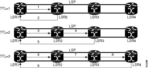
If you enter an LSP traceroute to an FEC at LSR4 from LSR1, you get the results shown in the table below.
| Table 2 | MPLS LSP Traceroute Example |
MPLS Network Management with MPLS LSP Ping and MPLS LSP Traceroute
To manage an MPLS network, you must have the ability to monitor LSPs and quickly isolate MPLS forwarding problems. You need ways to characterize the liveliness of an LSP and reliably detect when an LSP fails to deliver user traffic.
You can use MPLS LSP ping to verify the LSP that is used to transport packets destined for IPv4 LDP prefixes, and AToM PW FECs. You can use MPLS LSP traceroute to trace LSPs that are used to carry packets destined for IPv4 LDP prefixes.
An MPLS echo request is sent through an LSP to validate it. A TTL expiration or LSP breakage causes the transit router to process the echo request before it gets to the intended destination. The router returns an MPLS echo reply that contains an explanatory reply code to the originator of the echo request.
The successful echo request is processed at the egress of the LSP. The echo reply is sent via an IP path, an MPLS path, or a combination of both back to the originator of the echo request.
Any Transport over MPLS Virtual Circuit Connection
AToM Virtual Circuit Connection Verification (VCCV) allows you to send control packets inband of an AToM PW from the originating provider edge (PE) router. The transmission is intercepted at the destination PE router, instead of being forwarded to the customer edge (CE) router. This capability allows you to use MPLS LSP ping to test the PW section of AToM virtual circuits (VCs).
LSP ping allows verification of AToM VC setup by FEC 128 or FEC 129. FEC 128-based AToM VCs can be set up by using LDP for signaling or by using a static pseudowire configuration without using any signaling component on the two endpoints. Cisco software does not distinguish between FEC 128 and FEC 129 static pseudowires while issuing MPLS ping; the same commands are used.
AToM VCCV consists of the following:
- AToM VCCV Signaling
- Selection of AToM VCCV Switching Types
- Information Provided by the Router Processing LSP Ping or LSP Traceroute
AToM VCCV Signaling
One of the steps involved in AToM VC setup is the signaling or communication of VC labels and AToM VCCV capabilities between AToM VC endpoints. To communicate the AToM VCCV disposition capabilities of each endpoint, the router uses an optional parameter, defined in the IETF Internet Draft Pseudo Wire (PW) Virtual Circuit Connection Verification (VCCV) (draft-ieft-pwe3-vccv-01).
The AToM VCCV disposition capabilities are categorized as follows:
- Applications--MPLS LSP ping and ICMP ping are applications that AToM VCCV supports to send packets inband of an AToM PW for control purposes.
- Switching modes--Type 1 and Type 2 are switching modes that AToM VCCV uses for differentiating between control and data traffic.
The table below describes AToM VCCV Type 1 and Type 2 switching modes.
Selection of AToM VCCV Switching Types
Cisco routers always use Type 1 switching, if available, when they send MPLS LSP ping packets over an AToM VC control channel. Type 2 switching accommodates those VC types and implementations that do not support or interpret the AToM control word.
The table below shows the AToM VCCV switching mode advertised and the switching mode selected by the AToM VC.
| Table 4 | AToM VCCV Switching Mode Advertised and Selected by AToM VC |
|
Type Advertised |
Type Selected |
|---|---|
|
AToM VCCV not supported |
-- |
|
Type 1 AToM VCCV switching |
Type 1 AToM VCCV switching |
|
Type 2 AToM VCCV switching |
Type 2 AToM VCCV switching |
|
Type 1 and Type 2 AToM VCCV switching |
Type 1 AToM VCCV switching |
An AToM VC advertises its AToM VCCV disposition capabilities in both directions: that is, from the originating router (PE1) to the destination router (PE2), and from PE2 to PE1.
In some instances, AToM VCs might use different switching types if the two endpoints have different AToM VCCV capabilities. If PE1 supports Type 1 and Type 2 AToM VCCV switching and PE2 supports only Type 2 AToM VCCV switching, there are two consequences:
- LSP ping packets sent from PE1 to PE2 are encapsulated with Type 2 switching.
- LSP ping packets sent from PE2 to PE1 use Type 1 switching.
You can determine the AToM VCCV capabilities advertised to and received from the peer by entering the show mpls l2transport binding command at the PE router.
Information Provided by the Router Processing LSP Ping or LSP Traceroute
The table below describes the characters that the router processing an LSP ping or LSP traceroute packet returns to the sender about the failure or success of the request.
You can also display the return code for an MPLS LSP Ping operation if you enter the ping mpls verbose command.
| Table 5 | Echo Reply Return Codes |
|
Output Code |
Echo Return Code |
Meaning |
|---|---|---|
|
x |
0 |
No return code. |
|
M |
1 |
Malformed echo request. |
|
m |
2 |
Unsupported TLVs. |
|
! |
3 |
Success. |
|
F |
4 |
No FEC mapping. |
|
D |
5 |
DS Map mismatch. |
|
I |
6 |
Unknown Upstream Interface index. |
|
U |
7 |
Reserved. |
|
L |
8 |
Labeled output interface. |
|
B |
9 |
Unlabeled output interface. |
|
f |
10 |
FEC mismatch. |
|
N |
11 |
No label entry. |
|
P |
12 |
No receive interface label protocol. |
|
p |
13 |
Premature termination of the LSP. |
|
X |
unknown |
Undefined return code. |
Note | Echo return codes 6 and 7 are accepted only for Version 3 (draft-ieft-mpls-ping-03). |
IP Does Not Forward MPLS Echo Request Packets
MPLS echo request packets sent during an LSP ping are never forwarded by IP. The IP header destination address field in an MPLS echo request packet is a 127.x.y.z /8 address. Routers should not forward packets using a 127.x.y.z /8 address. The 127.x.y.z /8 address corresponds to an address for the local host.
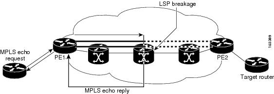
Use of a 127.x .y .z address as the destination address of the UDP packet is significant because the MPLS echo request packet fails to make it to the target router if a transit router does not label switch the LSP. The use of the 127.x .y .z address allows for the detection of LSP breakages. The following occurs at the transit router:
- If an LSP breakage occurs at a transit router, the MPLS echo packet is not forwarded; it is consumed by the router.
- If the LSP is intact, the MPLS echo packet reaches the target router and is processed by the terminal point of the LSP.
The figure below shows the path of the MPLS echo request and reply when a transit router fails to label switch a packet in an LSP.
Compatibility Between the MPLS LSP and Ping or Traceroute Implementations
LSP ping drafts after Version 3 (draft-ietf-mpls-ping-03) have undergone numerous TLV format changes, but the versions of the draft do not always interoperate.
To allow later Cisco implementations to interoperate with draft Version 3 Cisco and non-Cisco implementations, use a global configuration mode to decode echo packets in formats understood by draft Version 3 implementations.
Unless configured otherwise, a Cisco implementation encodes and decodes echo requests assuming the version on which the IETF implementations is based.
To prevent failures reported by the replying router due to TLV version issues, you should configure all routers in the core. Encode and decode MPLS echo packets in the same draft version. For example, if the network is running RFC 4379 (Cisco Version 4) implementations but one router is capable of only Version 3 (Cisco Revision 3), configure all routers in the network to operate in Revision 3 mode.
The Cisco implementation of MPLS echo request and echo reply is based on the IETF RFC 4379. IEFT drafts subsequent to this RFC (drafts 3, 4, 5, 6, and 7) introduced TLV format differences. These differences could not be identified because the echo packet had no way to differentiate between one TLV format and another TLV format. This introduced limited compatibility between the MPLS LSP Ping Traceroute implementations in the Cisco IOS 12.0(27)S1 and 12.0(27)S2 releases and the MPLS ping or traceroute implementation in later Cisco IOS releases. To allow interoperability between these releases, a revision keyword was added for the ping mpls and trace mpls commands. The revision keyword enables Cisco IOS releases to support the existing draft changes and any changes from future versions of the IETF LSP Ping draft.
Note | We recommend that you use the mpls oam global configuration command instead of the revision option. |
CiscoVendorExtensions
In Cisco's Version 3 (draft-ietf-mpls-ping-03.txt) implementations, Cisco defined a vendor extension TLV in the ignore-if-not-understood TLV space. It is used for the following purposes:
The first capability was defined before the existence of the global configuration command for setting the echo packet encode and decode behavior. TLV version information in an echo packet overrides the configured decoding behavior. Using this TLV for TLV versions is no longer required since the introduction of the global configuration capability.
The second capability controls the reply DSCP. Draft Version 8 defines a Reply TOS TLV, so the use of the reply DSCP is no longer required.
You enable compatibility between the MPLS LSP and ping or traceroute implementation by customizing the default behavior of echo packets.
DSCP Option to Request a Specific Class of Service in an Echo Reply
Cisco software includes a reply differentiated services code point (DSCP) option that lets you request a specific class of service (CoS) in an echo reply.
The reply DSCP option is supported in the experimental mode for IETF draft-ietf-mpls-lsp-ping-03.txt. Cisco implemented a vendor-specific extension for the reply DSCP option rather than using a Reply TOS TLV. A Reply TOS TLV serves the same purpose as the reply dscp command in RFC 4379. This draft provides a standardized method of controlling the reply DSCP.
Reply Modes for an MPLS LSP Ping and LSP Traceroute Echo Request Response
The reply mode controls how a responding router replies to an MPLS echo request sent by a ping mpls or trace mpls command. There are two reply modes for an echo request packet:
- ipv4--Reply with an IPv4 UDP packet (default)
- router-alert--Reply with an IPv4 UDP packet with router alert
IPv4 Reply Mode
IPv4 packet is the most common reply mode used with a ping mpls or trace mpls command when you want to periodically poll the integrity of an LSP. With this option, you do not have explicit control over whether the packet traverses IP or MPLS hops to reach the originator of the MPLS echo request. If the originating (headend) router fails to receive a reply to an MPLS echo request when you use the reply mode ipv4 keywords, use the reply mode router-alert keywords.
Router-Alert Reply Mode
The router-alert reply mode adds the router alert option to the IP header. When an IP packet that contains an IP router alert option in its IP header or an MPLS packet with a router alert label as its outermost label arrives at a router, the router punts (redirects) the packet to the Route Processor (RP) level for handling. This forces the Cisco router to handle the packet at each intermediate hop as it moves back to the destination. Hardware and line-card forwarding inconsistencies are bypassed. Router-alert reply mode is more expensive than IPv4 mode because the reply goes hop-by-hop. It also is slower, so the sender receives a reply in a relatively longer period of time.
The table below describes how IP and MPLS packets with an IP router alert option are handled by the router switching path processes.
| Table 6 | Path Process Handling of IP and MPLS Router Alert Packets |
|
Incoming Packet |
Normal Switching Action |
Process Switching Action |
Outgoing Packet |
|---|---|---|---|
|
IP packet--Router alert option in IP header |
Router alert option in IP header causes the packet to be punted to the process switching path. |
Forwards the packet as is |
IP packet--Router alert option in IP header |
|
Forwards the packet as is |
MPLS packet |
||
|
MPLS packet-- Outermost label contains a router alert |
If the router alert label is the outermost label, it causes the packet to be punted to the process switching path. |
Removes the outermost router alert label and forwards the packet as an IP packet |
IP packet--Router alert option in IP header |
|
Preserves the outermost router alert label and forwards the MPLS packet |
MPLS packet-- Outermost label contains a router alert. |
LSP Breaks
If there is a problem forwarding MPLS packets in your network, you can determine where there are LSP breaks. This section describes MTU discovery in an LSP.
Untagged output interfaces at a penultimate hop do not impact the forwarding of IP packets through an LSP because the forwarding decision is made at the penultimate hop through use of the incoming label. However, untagged output interfaces cause AToM and MPLS VPN traffic to be dropped at the penultimate hop.
During an MPLS LSP ping, MPLS echo request packets are sent with the IP packet attribute set to "do not fragment." That is, the Don't Fragment (DF) bit is set in the IP header of the packet. This allows you to use the MPLS echo request to test for the MTU that can be supported for the packet through the LSP without fragmentation.
The figure below shows a sample network with a single LSP from PE1 to PE2 formed with labels advertised by the LDP.
You can determine the maximum receive unit (MRU) at each hop by using the MPLS Traceroute feature to trace the LSP. The MRU is the maximum size of a labeled packet that can be forwarded through an LSP.
How to Configure MPLS LSP Ping Traceroute for LDP TE and LSP Ping for VCCV
- Enabling Compatibility Between the MPLS LSP and Ping or Traceroute Implementation
- Validating an LDP IPv4 FEC by Using MPLS LSP Ping and MPLS LSP Traceroute
- Validating a Layer 2 FEC by Using MPLS LSP Ping and MPLS LSP Traceroute
- Using DSCP to Request a Specific Class of Service in an Echo Reply
- Controlling How a Responding Router Replies to an MPLS Echo Request
- Using MPLS LSP Ping to Discover Possible Loops
- Using MPLS LSP Traceroute to Discover Possible Loops
- Tracking Packets Tagged as Implicit Null
- Tracking Untagged Packets
- Determining Why a Packet Could Not Be Sent
- Detecting LSP Breaks when Load Balancing Is Enabled for IPv4 LDP LSPs
- Specifying the Interface Through Which Echo Packets Leave a Router
- Pacing the Transmission of Packets
- Interrogating the Transit Router for Its Downstream Information by Using Echo Request request-dsmap
- Interrogating a Router for Its DSMAP
- Requesting that a Transit Router Validate the Target FEC Stack
- Enabling LSP Ping to Detect LSP Breakages Caused by Untagged Interfaces
- Viewing the AToM VCCV Capabilities Advertised to and Received from the Peer
Enabling Compatibility Between the MPLS LSP and Ping or Traceroute Implementation
DETAILED STEPS
Validating an LDP IPv4 FEC by Using MPLS LSP Ping and MPLS LSP Traceroute
DETAILED STEPS
Validating a Layer 2 FEC by Using MPLS LSP Ping and MPLS LSP Traceroute
DETAILED STEPS
Using DSCP to Request a Specific Class of Service in an Echo Reply
DETAILED STEPS
Controlling How a Responding Router Replies to an MPLS Echo Request
DETAILED STEPS
Using MPLS LSP Ping to Discover Possible Loops
With the MPLS LSP Ping feature, loops can occur if you use the UDP destination address range, repeat option, or sweep option.
To use MPLS LSP ping to discover possible loops, perform the following steps.
DETAILED STEPS
| Command or Action | Purpose | |
|---|---|---|
Step 1 |
enable
Example: Router> enable |
Enables privileged EXEC mode. |
Step 2 |
ping mpls {ipv4
destination-address/destination-mask
[destination
address-start
address-end
increment | [pseudowire
ipv4-address
vc-id
vc-id
address-end
increment ]} [repeat
count] [sweep
minimum
maximum
size-increment]
Example: Router# ping mpls ipv4 10.131.159.251/32 destination 127.0.0.1 127.0.0.2 1 repeat 2 sweep 1450 1475 25 |
Checks MPLS LSP connectivity. |
Step 3 |
exit
Example: Router# exit |
Returns to user EXEC mode. |
Using MPLS LSP Traceroute to Discover Possible Loops
With the MPLS LSP Traceroute feature, loops can occur if you use the UDP destination address range option and the time-to-live option.
By default, the maximum TTL is set to 30. Therefore, the traceroute output may contain 30 lines if the target of the traceroute is not reached, which can happen when an LSP problem exists. If an LSP problem occurs, there may be duplicate entries. The router address of the last point that the trace reaches is repeated until the output is 30 lines. You can ignore the duplicate entries.
DETAILED STEPS
| Command or Action | Purpose | |
|---|---|---|
Step 1 |
enable
Example: Router> enable |
Enables privileged EXEC mode. |
Step 2 |
trace
mpls
ipv4
destination-address
/destination-mask [destination
address-start
address-end
address
increment] [ttl
maximum-time-to-live]
Example: Router# trace mpls ipv4 10.131.159.251/32 destination 127.0.0.1 127.0.0.3 1 ttl 5 |
Discovers MPLS LSP routes that packets take when traveling to their destinations. The example shows how a loop can occur. |
Step 3 |
exit
Example: Router# exit |
Returns to user EXEC mode. |
Tracking Packets Tagged as Implicit Null
DETAILED STEPS
| Command or Action | Purpose | |
|---|---|---|
Step 1 |
enable
Example: Router> enable |
Enables privileged EXEC mode. |
Step 2 |
trace mpls ipv4
destination-address/destination-mask
Example: Router# trace mpls ipv4 10.131.159.252/32 |
Discovers MPLS LSP routes that packets actually take when traveling to their destinations. |
Step 3 |
exit
Example: Router# exit |
Returns to user EXEC mode. |
Tracking Untagged Packets
DETAILED STEPS
| Command or Action | Purpose | |
|---|---|---|
Step 1 |
enable
Example: Router> enable |
Enables privileged EXEC mode. |
Step 2 |
show mpls forwarding-table
destination-address/destination-mask
Example: Router# show mpls forwarding-table 10.131.159.252/32 |
Displays the content of the MPLS Label Forwarding Information Base (LFIB) and displays whether the LDP is properly configured. |
Step 3 |
show mpls ldp discovery
Example: Router# show mpls ldp discovery |
Displays the status of the LDP discovery process and displays whether the LDP is properly configured. |
Step 4 |
exit
Example: Router# exit |
Returns to user EXEC mode. |
Determining Why a Packet Could Not Be Sent
The Q return code means that the packet could not be sent. The problem can be caused by insufficient processing memory, but it probably results because an LSP could not be found that matches the FEC information that was entered on the command line.
You need to determine the reason why the packet was not forwarded so that you can fix the problem in the path of the LSP. To do so, look at the Routing Information Base (RIB), the Forwarding Information Base (FIB), the Label Information Base (LIB), and the MPLS LFIB. If there is no entry for the FEC in any of these routing or forwarding bases, there is a Q return code.
To determine why a packet could not be transmitted, perform the following steps.
DETAILED STEPS
| Command or Action | Purpose | |
|---|---|---|
Step 1 |
enable
Example: Router> enable |
Enables privileged EXEC mode. |
Step 2 |
show ip route [ip-address [mask]]
Example: Router# show ip route 10.0.0.1 |
Displays the current state of the routing table. When the MPLS echo reply returns a Q, troubleshooting occurs on the routing information database. |
Step 3 |
show mpls forwarding-table [network {mask |
length} |
labels
label[-label] |
interface
interface |
next-hop
address |
lsp-tunnel [tunnel-id]]
Example: Router# show mpls forwarding-table 10.0.0.1/32 |
Displays the content of the MPLS LFIB. When the MPLS echo reply returns a Q, troubleshooting occurs on a label information database and an MPLS forwarding information database. |
Step 4 |
exit
Example: Router# exit |
Returns to user EXEC mode. |
Detecting LSP Breaks when Load Balancing Is Enabled for IPv4 LDP LSPs
An ICMP ping or trace follows one path from the originating router to the target router. Round robin load balancing of IP packets from a source router discovers the various output paths to the target IP address.
For MPLS ping and traceroute, Cisco routers use the source and destination addresses in the IP header for load balancing when multiple paths exist through the network to a target router. The Cisco implementation of MPLS may check the destination address of an IP payload to accomplish load balancing (the type of checking depends on the platform).
To detect LSP breaks when load balancing is enabled for IPv4 LDP LSPs, perform the following steps.
DETAILED STEPS
| Command or Action | Purpose | |
|---|---|---|
Step 1 |
enable
Example: Router> enable |
Enables privileged EXEC mode. |
Step 2 |
ping mpls ipv4
destination-address/destination-mask-length [destination
address-start
address-end
increment]
Example: Router# ping mpls ipv4 10.131.159.251/32 destination 127.0.0.1/8 |
Checks for load balancing paths. Enter the 127.z.y.x /8 destination address. |
Step 3 |
exit
Example: Router# exit |
Returns to user EXEC mode. |
Specifying the Interface Through Which Echo Packets Leave a Router
You can control the interface through which packets leave a router. Path output information is used as input to LSP ping and traceroute.
The echo request output interface control feature allows you to force echo packets through the paths that perform detailed debugging or characterizing of the LSP. This feature is useful if a PE router connects to an MPLS cloud and there are broken links. You can direct traffic through a certain link. The feature also is helpful for troubleshooting network problems.
To specify the output interface for echo requests, perform the following steps.
DETAILED STEPS
| Command or Action | Purpose | |||
|---|---|---|---|---|
Step 1 |
enable
Example: Router> enable |
Enables privileged EXEC mode. | ||
Step 2 | Enter one of the following commands:
Example: Router# ping mpls ipv4 10.131.159.251/32 output interface fastethernet0/0/0 Example: Router# trace mpls ipv4 10.131.159.251/32 output interface fastethernet0/0/0 |
Checks MPLS LSP connectivity. or Discovers MPLS LSP routes that packets actually take when traveling to their destinations.
| ||
Step 3 |
exit
Example: Router# exit |
Returns to user EXEC mode. |
Pacing the Transmission of Packets
Echo request traffic pacing allows you to pace the transmission of packets so that the receiving router does not drop packets. To perform echo request traffic pacing, perform the following steps.
DETAILED STEPS
| Command or Action | Purpose | |||
|---|---|---|---|---|
Step 1 |
enable
Example: Router> enable |
Enables privileged EXEC mode. | ||
Step 2 |
Checks MPLS LSP connectivity. or Discovers MPLS LSP routes that packets take when traveling to their destinations.
| |||
Step 3 |
exit
Example: Router# exit |
Returns to user EXEC mode. |
Interrogating the Transit Router for Its Downstream Information by Using Echo Request request-dsmap
The echo request request-dsmap capability troubleshooting feature, used in conjunction with the TTL flag, allows you to selectively interrogate a transit router. If there is a failure, you do not have to enter an lsp traceroute command for each previous failure; you can focus just on the failed hop.
A request-dsmap flag in the downstream mapping flags field, and procedures that specify how to trace noncompliant routers allow you to arbitrarily time-to-live (TTL) expire MPLS echo request packets with a wildcard downstream map (DSMAP).
Echo request DSMAPs received without labels indicate that the sender did not have any DSMAPs to validate. If the downstream router ID field of the DSMAP TLV in an echo request is set to the ALLROUTERs address (224.0.0.2) and there are no labels, the source router can arbitrarily query a transit router for its DSMAP information.
The ping mpls command allows an MPLS echo request to be TTL-expired at a transit router with a wildcard DSMAP for the explicit purpose of troubleshooting and querying the downstream router for its DSMAPs. The default is that the DSMAP has an IPv4 bitmap hashkey. You also can select hashkey 0 (none). The purpose of the ping mpls command is to allow the source router to selectively TTL expire an echo request at a transit router to interrogate the transit router for its downstream information. The ability to also select a multipath (hashkey) type allows the transmitting router to interrogate a transit router for load-balancing information as is done with multipath LSP traceroute, but without having to interrogate all subsequent nodes traversed between the source router and the router on which each echo request TTL expires. Use an echo request in conjunction with the TTL setting because if an echo request arrives at the egress of the LSP with an echo request, the responding routers never return DSMAPs.
To interrogate the transit router for its downstream information so that you can focus just on the failed hop if there is a failure, perform the following steps.
DETAILED STEPS
| Command or Action | Purpose | |||
|---|---|---|---|---|
Step 1 |
enable
Example: Router> enable |
Enables privileged EXEC mode. | ||
Step 2 |
ping mpls {ipv4
destination-address/destination-mask |
pseudowire
ipv4-address
vc-id
vc-id} [dsmap [hashkey {none |
ipv4 bitmap
bitmap-size}]]
Example: Router# ping mpls ipv4 10.161.251/32 dsmap hashkey ipv4 bitmap 16 |
Checks MPLS LSP connectivity.
| ||
Step 3 |
exit
Example: Router# exit |
Returns to user EXEC mode. |
Interrogating a Router for Its DSMAP
The router can interrogate the software or hardware forwarding layer for the depth limit that needs to be returned in the DSMAP TLV. If forwarding does not provide a value, the default is 255.
To determine the depth limit, specify the dsmap and ttl keywords in the ping mpls command. The transit router will be interrogated for its DSMAP. The depth limit is returned with the echo reply DSMAP. A value of 0 means that the IP header is used for load balancing. Another value indicates that the IP header load balances up to the specified number of labels.
To interrogate a router for its DSMAP, perform the following steps.
DETAILED STEPS
| Command or Action | Purpose | |||
|---|---|---|---|---|
Step 1 |
enable
Example: Router> enable |
Enables privileged EXEC mode. | ||
Step 2 |
ping mpls {ipv4
destination-address/destination-mask |
pseudowire
ipv4-address
vc-id
vc-id}
ttl
time-to-live
dsmap
Example: Router# ping mpls ipv4 10.131.159.252/32 ttl 1 dsmap |
Checks MPLS LSP connectivity.
| ||
Step 3 |
exit
Example: Router# exit |
Returns to user EXEC mode. |
Requesting that a Transit Router Validate the Target FEC Stack
An MPLS echo request tests a particular LSP. The LSP to be tested is identified by the FEC stack.
To request that a transit router validate the target FEC stack, set the V flag from the source router by entering the flags fec keyword in the ping mpls and trace mpls commands. The default is that echo request packets are sent with the V flag set to 0.
To request that a transit router validate the target FEC stack, perform the following steps.
DETAILED STEPS
| Command or Action | Purpose | |||
|---|---|---|---|---|
Step 1 |
enable
Example: Router> enable |
Enables privileged EXEC mode. | ||
Step 2 | Do one of the following:
Example: Router# ping mpls ipv4 10.131.159.252/32 flags fec Example: Router# trace mpls ipv4 10.131.159.252/32 flags fec |
Checks MPLS LSP connectivity. or Discovers MPLS LSP routes that packets actually take when traveling to their destinations.
| ||
Step 3 |
exit
Example: Router# exit |
Returns to user EXEC mode. |
Enabling LSP Ping to Detect LSP Breakages Caused by Untagged Interfaces
For MPLS LSP ping and traceroute of LSPs carrying IPv4 FECs, you can force an explicit null label to be added to the MPLS label stack even though the label was unsolicited. This allows LSP ping to detect LSP breakages caused by untagged interfaces. LSP ping does not report that an LSP is operational when it is unable to send MPLS traffic.
An explicit null label is added to an MPLS label stack if MPLS echo request packets are forwarded from untagged interfaces that are directly connected to the destination of the LSP ping or if the IP TTL value for the MPLS echo request packets is set to 1.
When you enter an lsp ping command, you are testing the LSP's ability to carry IP traffic. Failure at untagged output interfaces at the penultimate hop are not detected. Explicit-null shimming allows you to test an LSP's ability to carry MPLS traffic.
To enable LSP ping to detect LSP breakages caused by untagged interfaces, specify the force-explicit-null keyword in the ping mpls or trace mpls commands as shown in the following steps.
DETAILED STEPS
| Command or Action | Purpose | |||
|---|---|---|---|---|
Step 1 |
enable
Example: Router> enable |
Enables privileged EXEC mode. | ||
Step 2 | Do one of the following:
Example: Router# ping mpls ipv4 10.131.191.252/32 force-explicit null Example: Router# trace mpls ipv4 10.131.191.252/32 force-explicit-null |
Checks MPLS LSP connectivity. or Discovers MPLS LSP routes that packets actually take when traveling to their destinations.
| ||
Step 3 |
exit
Example: Router# exit |
Returns to user EXEC mode. |
Viewing the AToM VCCV Capabilities Advertised to and Received from the Peer
To view the AToM VCCV capabilities advertised to and received from the peer, perform the following steps.
DETAILED STEPS
| Command or Action | Purpose | |
|---|---|---|
Step 1 |
enable
Example: Router> enable |
Enables privileged EXEC mode. |
Step 2 |
show mpls l2transport binding
Example: Router# show mpls l2transport binding |
Displays VC label binding information. |
Step 3 |
exit
Example: Router# exit |
Returns to user EXEC mode. |
Configuration Examples for MPLS LSP Ping Traceroute for LDP TE and LSP Ping for VCCV
- Enabling Compatibility Between the MPLS LSP and Ping or Traceroute Implementation Example
- Validating an LDP IPv4 FEC by Using MPLS LSP Ping and MPLS LSP Traceroute Example
- Validating a Layer 2 FEC by Using MPLS LSP Ping Example
- Using DSCP to Request a Specific Class of Service in an Echo Reply Example
- Controlling How a Responding Router Replies to an MPLS Echo Request Example
- Preventing Possible Loops with MPLS LSP Ping Example
- Preventing Possible Loops with MPLS LSP Traceroute Example
- Troubleshooting with LSP Ping or Traceroute Example
- MTU Discovery in an LSP Example
- Tracking Packets Tagged as Implicit Null Example
- Tracking Untagged Packets Example
- Determining Why a Packet Could Not Be Sent Example
- Detecting LSP Breaks when Load Balancing Is Enabled for IPv4 LSPs Example
- Specifying the Interface Through Which Echo Packets Leave a Router Example
- Pacing the Transmission of Packets Example
- Interrogating the Transit Router for Its Downstream Information Example
- Interrogating a Router for Its DSMAP Example
- Requesting that a Transit Router Validate the Target FEC Stack Example
- Enabling LSP Ping to Detect LSP Breakages Caused by Untagged Interfaces Example
- Viewing the AToM VCCV Capabilities Advertised to and Received from the Peer Example
Enabling Compatibility Between the MPLS LSP and Ping or Traceroute Implementation Example
The following example shows how to configure MPLS multipath LSP traceroute to interoperate with a vendor implementation that does not interpret RFC 4379 as Cisco does:
configure terminal
!
mpls oam
 echo revision 4
 no echo vendor-extension
 exit
The default echo revision number is 4, which corresponds to the IEFT draft 11.
Validating an LDP IPv4 FEC by Using MPLS LSP Ping and MPLS LSP Traceroute Example
The following example shows how to use the ping mpls command to test connectivity of an IPv4 LDP LSP:
Router# ping mpls ipv4 10.131.191.252/32 repeat 5 exp 5 verbose
Sending 5, 100-byte MPLS Echos to 10.131.191.252, timeout is 2 seconds:
Codes:
    '!' - success, 'Q' - request not sent, '.' - timeout,
    'L' - labeled output interface, 'B' - unlabeled output interface,
    'D' - DS Map mismatch, 'F' - no FEC mapping, 'f' - FEC mismatch,
    'M' - malformed request, 'm' - unsupported tlvs, 'N' - no rx label,
    'P' - no rx intf label prot, 'p' - premature termination of LSP,
    'R' - transit router, 'X' - unknown return code, 'x' - return code 0
Type escape sequence to abort.
!     10.131.191.230, return code 3
!     10.131.191.230, return code 3
!     10.131.191.230, return code 3
!     10.131.191.230, return code 3
!     10.131.191.230, return code 3
Success rate is 100 percent (5/5), round-trip min/avg/max = 100/10
Validating a Layer 2 FEC by Using MPLS LSP Ping Example
The following example validates a Layer 2 FEC:
Router# ping mpls pseudowire 10.10.10.15 108 vc-id 333

Sending 5, 100-byte MPLS Echos to 10.10.10.15,
      timeout is 2 seconds, send interval is 0 msec:
Codes: '!' - success, 'Q' - request not sent, '.' - timeout,
   'L' - labeled output interface, 'B' - unlabeled output interface,
   'D' - DS Map mismatch, 'F' - no FEC mapping, 'f' - FEC mismatch,
   'M' - malformed request, 'm' - unsupported tlvs, 'N' - no label entry,
   'P' - no rx intf label prot, 'p' - premature termination of LSP,
   'R' - transit router, 'I' - unknown upstream index,
   'X' - unknown return code, 'x' - return code 0
Type escape sequence to abort.
!!!!!
Success rate is 100 percent (5/5), round-trip min/avg/max = 28/32/40 ms PE-802#
Using DSCP to Request a Specific Class of Service in an Echo Reply Example
The following example shows how to use DSCP to request a specific CoS in an echo reply:
Router# ping mpls ipv4 10.131.159.252/32 reply dscp 50
 <0-63>   Differentiated services codepoint value
 af11     Match packets with AF11 dscp (001010)
 af12     Match packets with AF12 dscp (001100)
 af13     Match packets with AF13 dscp (001110)
 af21     Match packets with AF21 dscp (010010)
 af22     Match packets with AF22 dscp (010100)
 af23     Match packets with AF23 dscp (010110)
 af31     Match packets with AF31 dscp (011010)
 af32     Match packets with AF32 dscp (011100)
 af33     Match packets with AF33 dscp (011110)
 af41     Match packets with AF41 dscp (100010)
 af42     Match packets with AF42 dscp (100100)
 af43     Match packets with AF43 dscp (100110)
 cs1      Match packets with CS1(precedence 1) dscp (001000)
 cs2      Match packets with CS2(precedence 2) dscp (010000)
 cs3      Match packets with CS3(precedence 3) dscp (011000)
 cs4      Match packets with CS4(precedence 4) dscp (100000)
 cs5      Match packets with CS5(precedence 5) dscp (101000)
 cs6      Match packets with CS6(precedence 6) dscp (110000)
 cs7      Match packets with CS7(precedence 7) dscp (111000)
 default  Match packets with default dscp (000000)
 ef       Match packets with EF dscp (101110)
Preventing Possible Loops with MPLS LSP Ping Example
The following example shows how a loop operates if you use the following ping mpls command:
Router# ping mpls
 ipv4
 10.131.159.251/32 destination 127.0.0.1 127.0.0.2 1 repeat 2
sweep 1450 1475 25
Sending 2, [1450..1500]-byte MPLS Echos to 10.131.159.251/32,
     timeout is 2 seconds, send interval is 0 msec:
Codes:
    '!' - success, 'Q' - request not sent, '.' - timeout,
    'L' - labeled output interface, 'B' - unlabeled output interface,
    'D' - DS Map mismatch, 'F' - no FEC mapping, 'f' - FEC mismatch,
    'M' - malformed request, 'm' - unsupported tlvs, 'N' - no rx label,
    'P' - no rx intf label prot, 'p' - premature termination of LSP,
    'R' - transit router, 'X' - unknown return code, 'x' - return code 0
Type escape sequence to abort.
Destination address 127.0.0.1
!
!
Destination address 127.0.0.2
!
!
Destination address 127.0.0.1
!
!
Destination address 127.0.0.2
!
!
A ping mpls command is sent for each packet size range for each destination address until the end address is reached. For this example, the loop continues in the same manner until the destination address, 127.0.0.5, is reached. The sequence continues until the number is reached that you specified with the repeat count keyword and argument. For this example, the repeat count is 2. The MPLS LSP ping loop sequence is as follows:
repeat  = 1
  destination address 1 (address-start
)
    for (size from sweep minimum
 to maximum
, counting by size-increment
)
      send an lsp ping
  destination address 2 (address-start
 +
address-
increment
)
    for (size from sweep minimum
 to maximum
, counting by size-increment
)
      send an lsp ping
  destination address 3 (address-start
 +
address-
increment
 +
address-
increment
)
     for (size from sweep minimum
 to maximum
, counting by size-increment
)
      send an lsp ping
  .
  .
  .
  until destination address = address-end
  .
  .
  .
  until repeat = count 2
Preventing Possible Loops with MPLS LSP Traceroute Example
The following example shows how a loop occurs if you use the following trace mpls command:
Router# trace mpls ipv4 10.131.159.251/32 destination 127.0.0.1 127.0.0.3 1 ttl 5
Tracing MPLS Label Switched Path to 10.131.159.251/32, timeout is 2 seconds
Codes:
    '!' - success, 'Q' - request not sent, '.' - timeout,
    'L' - labeled output interface, 'B' - unlabeled output interface,
    'D' - DS Map mismatch, 'F' - no FEC mapping, 'f' - FEC mismatch,
    'M' - malformed request, 'm' - unsupported tlvs, 'N' - no rx label,
    'P' - no rx intf label prot, 'p' - premature termination of LSP,
    'R' - transit router, 'X' - unknown return code, 'x' - return code 0
Type escape sequence to abort.
Destination address 127.0.0.1
  0 10.131.191.230 MRU 1500 [Labels: 19 Exp: 0]
R 1 10.131.159.226 MRU 1504 [implicit-null] 40 ms
! 2 10.131.159.225 40 ms
Destination address 127.0.0.2
  0 10.131.191.230 MRU 1500 [Labels: 19 Exp: 0]
R 1 10.131.159.226 MRU 1504 [implicit-null] 40 ms
! 2 10.131.159.225 40 ms
Destination address 127.0.0.3
  0 10.131.191.230 MRU 1500 [Labels: 19 Exp: 0]
R 1 10.131.159.226 MRU 1504 [implicit-null] 40 ms
! 2 10.131.159.225 48 ms
An mpls trace command is sent for each TTL from 1 to the maximum TTL (ttl maximum-time-to-live keyword and argument) for each destination address until the address specified with the destination end-address argument is reached. In this example, the maximum TTL is 5 and the end destination address is 127.0.0.3. The MPLS LSP traceroute loop sequence is as follows:
destination address 1 (address-start
)
  for (ttl from 1 to maximum-time-to-live
)
    send an lsp trace
destination address 2 (address-start
 + address-increment
)
  for (ttl from 1 to 5
)
    send an lsp trace
destination address 3 (address-start
 + address-increment
 + address-increment
)
  for (ttl from 1 to
maximum-time-to-live)
    send an lsp trace
.
.
.
until destination address = 4
The following example shows that the trace encountered an LSP problem at the router that has an IP address of 10.6.1.6:
Router# traceroute mpls ipv4 10.6.7.4/32
Tracing MPLS Label Switched Path to 10.6.7.4/32, timeout is 2 seconds
Codes:
    '!' - success, 'Q' - request not sent, '.' - timeout,
    'L' - labeled output interface, 'B' - unlabeled output interface,
    'D' - DS Map mismatch, 'F' - no FEC mapping, 'f' - FEC mismatch,
    'M' - malformed request, 'm' - unsupported tlvs, 'N' - no rx label,
    'P' - no rx intf label prot, 'p' - premature termination of LSP,
    'R' - transit router, 'X' - unknown return code, 'x' - return code 0
Type escape sequence to abort.
  0 10.6.1.14 MRU 4470 [Labels: 22 Exp: 0]
R 1 10.6.1.5 MRU 4470 [Labels: 21 Exp: 0] 2 ms
R 2 10.6.1.6 4 ms                  <------ Router address repeated for 2nd to 30th TTL.
R 3 10.6.1.6 1 ms
R 4 10.6.1.6 1 ms
R 5 10.6.1.6 3 ms
R 6 10.6.1.6 4 ms
R 7 10.6.1.6 1 ms
R 8 10.6.1.6 2 ms
R 9 10.6.1.6 3 ms
R 10 10.6.1.6 4 ms
R 11 10.6.1.6 1 ms
R 12 10.6.1.6 2 ms
R 13 10.6.1.6 4 ms
R 14 10.6.1.6 5 ms
R 15 10.6.1.6 2 ms
R 16 10.6.1.6 3 ms
R 17 10.6.1.6 4 ms
R 18 10.6.1.6 2 ms
R 19 10.6.1.6 3 ms
R 20 10.6.1.6 4 ms
R 21 10.6.1.6 1 ms
R 22 10.6.1.6 2 ms
R 23 10.6.1.6 3 ms
R 24 10.6.1.6 4 ms
R 25 10.6.1.6 1 ms
R 26 10.6.1.6 3 ms
R 27 10.6.1.6 4 ms
R 28 10.6.1.6 1 ms
R 29 10.6.1.6 2 ms
R 30 10.6.1.6 3 ms                   <------ TTL 30.
If you know the maximum number of hops in your network, you can set the TTL to a lower value with the trace mpls ttl maximum-time-to-live command. The following example shows the same traceroute command as the previous example, except that this time the TTL is set to 5:
Router# traceroute mpls ipv4 10.6.7.4/32 ttl 5
Tracing MPLS Label Switched Path to 10.6.7.4/32, timeout is 2 seconds
Codes:
    '!' - success, 'Q' - request not sent, '.' - timeout,
    'L' - labeled output interface, 'B' - unlabeled output interface,
    'D' - DS Map mismatch, 'F' - no FEC mapping, 'f' - FEC mismatch,
    'M' - malformed request, 'm' - unsupported tlvs, 'N' - no rx label,
    'P' - no rx intf label prot, 'p' - premature termination of LSP,
    'R' - transit router, 'X' - unknown return code, 'x' - return code 0
Type escape sequence to abort.
  0 10.6.1.14 MRU 4470 [Labels: 22 Exp: 0]
R 1 10.6.1.5 MRU 4474 [No Label] 3 ms
R 2 10.6.1.6 4 ms                  <------ Router address repeated for 2nd to 5th TTL.
R 3 10.6.1.6 1 ms
R 4 10.6.1.6 3 ms
R 5 10.6.1.6 4 ms
Troubleshooting with LSP Ping or Traceroute Example
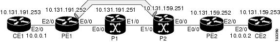
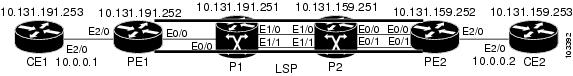
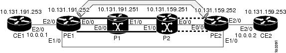
ICMP ping and trace commands are often used to help diagnose the root cause of a failure. When an LSP is broken, the packet may reach the target router by IP forwarding, thus making the ICMP ping and traceroute features unreliable for detecting MPLS forwarding problems. The MPLS LSP ping or traceroute and AToM VCCV features extend this diagnostic and troubleshooting ability to the MPLS network and handle inconsistencies (if any) between the IP and MPLS forwarding tables, inconsistencies in the MPLS control and data plane, and problems with the reply path.
The figure below shows a sample topology with an LDP LSP.
This section contains the following subsections:
- Configuration for Sample Topology
- Verification That the LSP Is Configured Correctly
- Discovery of LSP Breaks
Configuration for Sample Topology
These are sample topology configurations for the troubleshooting examples in the following sections (see the figure above). There are the six sample router configurations.
Router CE1 Configuration
Following is the configuration for the CE1 router:
!
version 12.4
service timestamps debug datetime msec
service timestamps log datetime msec
no service password-encryption
!
hostname CE1
!
boot-start-marker
boot-end-marker
!
enable password lab
!
clock timezone EST -5
ip subnet-zero
!
!
!
interface Loopback0
 ip address 10.131.191.253 255.255.255.255
 no ip directed-broadcast
 no clns route-cache
!
!
interface Ethernet2/0
 no ip address
 no ip directed-broadcast
 no keepalive
 no cdp enable
 no clns route-cache
!
interface Ethernet2/0.1
 encapsulation dot1Q 1000
 ip address 10.0.0.1 255.255.255.0
 no ip directed-broadcast
!
!
line con 0
 exec-timeout 0 0
line aux 0
line vty 0 4
 exec-timeout 0 0
 password lab
 login
!
end
Router PE1 Configuration
Following is the configuration for the PE1 router:
!
version 12.4
service timestamps debug datetime msec
service timestamps log datetime msec
no service password-encryption
!
hostname PE1
!
boot-start-marker
boot-end-marker
!
logging snmp-authfail
enable password lab
!
clock timezone EST -5
ip subnet-zero
ip cef
no ip domain-lookup
!
mpls ldp discovery targeted-hello accept
mpls ldp router-id Loopback0 force
mpls label protocol ldp
!
!
!
interface Loopback0
 ip address 10.131.191.252 255.255.255.255
 no clns route-cache
!
interface Ethernet0/0
 ip address 10.131.191.230 255.255.255.252
ip rsvp bandwidth 1500 1500
ip rsvp signalling dscp 0
!
interface Ethernet1/0
 ip address 10.131.159.246 255.255.255.252
 shutdown
 no clns route-cache
ip rsvp bandwidth 1500 1500
ip rsvp signalling dscp 0
!
interface Ethernet2/0
 no ip address
 no cdp enable
 no clns route-cache
!
interface Ethernet2/0.1
 encapsulation dot1Q 1000
 xconnect 10.131.159.252 333 encapsulation mpls
!
!
router ospf 1
 log-adjacency-changes
 passive-interface Loopback0
 network 10.131.159.244 0.0.0.3 area 0
 network 10.131.191.228 0.0.0.3 area 0
 network 10.131.191.232 0.0.0.3 area 0
 network 10.131.191.252 0.0.0.0 area 0
!
!
!
line con 0
 exec-timeout 0 0
line aux 0
line vty 0 4
 exec-timeout 0 0
 password lab
 login
!
!
end
Router P1 Configuration
Following is the configuration for the P1 router:
version 12.4
service timestamps debug datetime msec
service timestamps log datetime msec
no service password-encryption
!
hostname P1
!
boot-start-marker
boot-end-marker
!
logging snmp-authfail
enable password lab
!
clock timezone EST -5
ip subnet-zero
ip cef
no ip domain-lookup
!
!
mpls ldp discovery targeted-hello accept
mpls ldp router-id Loopback0 force
mpls label protocol ldp
!
!
!
 no clns route-cache
!
interface Loopback0
 ip address 10.131.191.251 255.255.255.255
 no clns route-cache
!
interface Ethernet0/0
 ip address 10.131.191.229 255.255.255.252
 no clns route-cache
ip rsvp bandwidth 1500 1500
ip rsvp signalling dscp 0
!
interface Ethernet1/0
 ip address 10.131.159.226 255.255.255.252
 no clns route-cache
ip rsvp bandwidth 1500 1500
ip rsvp signalling dscp 0
!
interface Ethernet1/1
 ip address 10.131.159.222 255.255.255.252
 no clns route-cache
ip rsvp bandwidth 1500 1500
ip rsvp signalling dscp 0
!
!
router ospf 1
 log-adjacency-changes
 passive-interface Loopback0
 network 10.131.159.220 0.0.0.3 area 0
 network 10.131.159.224 0.0.0.3 area 0
 network 10.131.191.228 0.0.0.3 area 0
 network 10.131.191.251 0.0.0.0 area 0
 mpls traffic-eng router-id Loopback0
 mpls traffic-eng area 0
!
!
line con 0
 exec-timeout 0 0
line aux 0
line vty 0 4
 exec-timeout 0 0
 password lab
 login
!
end
Router P2 Configuration
Following is the configuration for the P2 router:
!
version 12.4
service timestamps debug datetime msec
service timestamps log datetime msec
no service password-encryption
!
hostname P2
!
boot-start-marker
boot-end-marker
!
enable password lab
!
clock timezone EST -5
ip subnet-zero
ip cef
no ip domain-lookup
!
mpls ldp discovery targeted-hello accept
mpls ldp router-id Loopback0 force
mpls label protocol ldp
!
!
!
interface Loopback0
 ip address 10.131.159.251 255.255.255.255
 no ip directed-broadcast
!
interface Ethernet0/0
 ip address 10.131.159.229 255.255.255.252
 no ip directed-broadcast
ip rsvp bandwidth 1500 1500
ip rsvp signalling dscp 0
!
interface Ethernet0/1
 ip address 10.131.159.233 255.255.255.252
no ip directed-broadcast
ip rsvp signalling dscp 0
!
interface Ethernet1/0
 ip address 10.131.159.225 255.255.255.252
no ip directed-broadcast
ip rsvp bandwidth 1500 1500
ip rsvp signalling dscp 0
!
interface Ethernet1/1
 ip address 10.131.159.221 255.255.255.252
no ip directed-broadcast
ip rsvp signalling dscp 0
!
!
router ospf 1
 log-adjacency-changes
 passive-interface Loopback0
 network 10.131.159.220 0.0.0.3 area 0
 network 10.131.159.224 0.0.0.3 area 0
 network 10.131.159.228 0.0.0.3 area 0
 network 10.131.159.232 0.0.0.3 area 0
 network 10.131.159.251 0.0.0.0 area 0
!
!
!
line con 0
 exec-timeout 0 0
line aux 0
line vty 0 4
 exec-timeout 0 0
 password lab
 login
!
end
Router PE2 Configuration
Following is the configuration for the PE2 router:
!
version 12.4
service timestamps debug datetime msec
service timestamps log datetime msec
no service password-encryption
!
hostname PE2
!
boot-start-marker
boot-end-marker
!
logging snmp-authfail
enable password lab
!
clock timezone EST -5
ip subnet-zero
ip cef
no ip domain-lookup
!
mpls ldp discovery targeted-hello accept
mpls ldp router-id Loopback0 force
mpls label protocol ldp
!
!
!
interface Loopback0
 ip address 10.131.159.252 255.255.255.255
 no clns route-cache
!
interface Ethernet0/0
 ip address 10.131.159.230 255.255.255.252
 no clns route-cache
 ip rsvp bandwidth 1500 1500
 ip rsvp signalling dscp 0
!
interface Ethernet0/1
 ip address 10.131.159.234 255.255.255.252
 no clns route-cache
 ip rsvp bandwidth 1500 1500
 ip rsvp signalling dscp 0
!
interface Ethernet1/0
 ip address 10.131.159.245 255.255.255.252
 mpls ip
 no clns route-cache
!
interface Ethernet3/0
 no ip address
 no cdp enable
 no clns route-cache
!
interface Ethernet3/0.1
 encapsulation dot1Q 1000
 no snmp trap link-status
 no cdp enable
 xconnect 10.131.191.252 333 encapsulation mpls
!
!
router ospf 1
 log-adjacency-changes
 passive-interface Loopback0
 network 10.131.122.0 0.0.0.3 area 0
 network 10.131.159.228 0.0.0.3 area 0
 network 10.131.159.232 0.0.0.3 area 0
 network 10.131.159.236 0.0.0.3 area 0
 network 10.131.159.244 0.0.0.3 area 0
 network 10.131.159.252 0.0.0.0 area 0
!
!
line con 0
 exec-timeout 0 0
line aux 0
line vty 0 4
 exec-timeout 0 0
 password lab
 login
!
!
end
Router CE2 Configuration
Following is the configuration for the CE2 router:
!
version 12.4
service timestamps debug datetime msec
service timestamps log datetime msec
no service password-encryption
!
hostname CE2
!
boot-start-marker
boot-end-marker
!
enable password lab
!
clock timezone EST -5
ip subnet-zero
ip cef
no ip domain-lookup
!
!
interface Loopback0
 ip address 10.131.159.253 255.255.255.255
 no ip directed-broadcast
 no clns route-cache
!
interface Ethernet3/0
 no ip address
 no ip directed-broadcast
 no keepalive
 no cdp enable
 no clns route-cache
!
interface Ethernet3/0.1
 encapsulation dot1Q 1000
 ip address 10.0.0.2 255.255.255.0
 no ip directed-broadcast
!
!
line con 0
 exec-timeout 0 0
line aux 0
line vty 0 4
 exec-timeout 0 0
 password lab
 login
!
end
Verification That the LSP Is Configured Correctly
Use the output from the show commands in this section to verify that the LSP is configured correctly.
A show mpls forwarding-table command shows that tunnel 1 is in the MPLS forwarding table.
PE1# show mpls forwarding-table 10.131.159.252
Local  Outgoing    Prefix            Bytes tag  Outgoing   Next Hop
tag    tag or VC   or Tunnel Id      switched   interface
22     18
[T] 10.131.159.252/32 0          Tu1        point2point
[T]     Forwarding through a TSP tunnel.
        View additional tagging info with the 'detail' option
A trace mpls command issued at PE1 verifies that packets with 16 as the outermost label and 18 as the end-of-stack label are forwarded from PE1 to PE2.
PE1# trace mpls ipv4 10.131.159.252/32
Tracing MPLS Label Switched Path to 10.131.159.252/32, timeout is 2 seconds
Codes:
    '!' - success, 'Q' - request not sent, '.' - timeout,
    'L' - labeled output interface, 'B' - unlabeled output interface,
    'D' - DS Map mismatch, 'F' - no FEC mapping, 'f' - FEC mismatch,
    'M' - malformed request, 'm' - unsupported tlvs, 'N' - no rx label,
    'P' - no rx intf label prot, 'p' - premature termination of LSP,
    'R' - transit router, 'X' - unknown return code, 'x' - return code 0
Type escape sequence to abort.
   0 10.131.191.252 MRU 1496 [Labels: 16/18 Exp: 0/0] L 1 10.131.191.229
   MRU 1508 [Labels: 18 Exp: 0] 0 ms L 2 10.131.159.225
   MRU 1504 [Labels: implicit-null Exp: 0] 0 ms ! 3 10.131.159.234 20 ms
   PE1#
The MPLS LSP Traceroute to PE2 is successful, as indicated by the exclamation point (!).
Discovery of LSP Breaks
Use the output of the commands in this section to discover LSP breaks.
An LDP target session is established between routers PE1 and P2, as shown in the output of the following show mpls ldp discovery command:
PE1# show mpls ldp discovery
 Local LDP Identifier:
    10.131.191.252:0
    Discovery Sources:
    Interfaces:
        Ethernet0/0 (ldp): xmit/recv
            LDP Id: 10.131.191.251:0
        Tunnel1 (ldp): Targeted -> 10.131.159.251
    Targeted Hellos:
        10.131.191.252 -> 10.131.159.252 (ldp): active/passive, xmit/recv
            LDP Id: 10.131.159.252:0
        10.131.191.252 -> 10.131.159.251 (ldp): active, xmit/recv
LDP Id: 10.131.159.251:0
Enter the following command on the P2 router in global configuration mode:
P2(config)# no mpls ldp discovery targeted-hello accept
The LDP configuration change causes the targeted LDP session between the headend and tailend of the TE tunnel to go down. Labels for IPv4 prefixes learned by P2 are not advertised to PE1. Thus, all IP prefixes reachable by P2 are reachable by PE1 only through IP (not MPLS). In other words, packets destined for those prefixes through Tunnel 1 at PE1 will be IP switched at P2 (which is undesirable).
The following show mpls ldp discovery command shows that the LDP targeted session is down:
PE1# show mpls ldp discovery
 Local LDP Identifier:
    10.131.191.252:0
    Discovery Sources:
    Interfaces:
        Ethernet0/0 (ldp): xmit/recv
            LDP Id: 10.131.191.251:0
        Tunnel1 (ldp): Targeted -> 10.131.159.251
    Targeted Hellos:
        10.131.191.252 -> 10.131.159.252 (ldp): active/passive, xmit/recv
            LDP Id: 10.131.159.252:0
        10.131.191.252 -> 10.131.159.251 (ldp): active, xmit
Enter the show mpls forwarding-table command at the PE1 router. The display shows that the outgoing packets are untagged as a result of the LDP configuration changes.
PE1# show mpls forwarding-table 10.131.159.252
Local  Outgoing    Prefix            Bytes tag  Outgoing   Next Hop
tag    tag or VC   or Tunnel Id      switched   interface
22     Untagged[T] 10.131.159.252/32 0          Tu1        point2point
[T]     Forwarding through a TSP tunnel.
        View additional tagging info with the 'detail' option
A ping mpls command entered at the PE1 router displays the following:
PE1# ping mpls ipv4 10.131.159.252/32 repeat 1
Sending 1, 100-byte MPLS Echos to 10.131.159.252/32,
      timeout is 2 seconds, send interval is 0 msec:
Codes:
    '!' - success, 'Q' - request not sent, '.' - timeout,
    'L' - labeled output interface, 'B' - unlabeled output interface,
    'D' - DS Map mismatch, 'F' - no FEC mapping, 'f' - FEC mismatch,
    'M' - malformed request, 'm' - unsupported tlvs, 'N' - no rx label,
    'P' - no rx intf label prot, 'p' - premature termination of LSP,
    'R' - transit router, 'X' - unknown return code, 'x' - return code 0
Type escape sequence to abort.
R
Success rate is 0 percent (0/1)
The ping mpls command fails. The R indicates that the sender of the MPLS echo reply had a routing entry but no MPLS FEC. Entering the verbose keyword with the ping mpls command displays the MPLS LSP echo reply sender address and the return code. You should be able to determine where the breakage occurred by telnetting to the replying router and inspecting its forwarding and label tables. You might need to look at the neighboring upstream router as well, because the breakage might be on the upstream router.
PE1# ping mpls ipv4 10.131.159.252/32 repeat 1 verbose
Sending 1, 100-byte MPLS Echos to 10.131.159.252/32,
      timeout is 2 seconds, send interval is 0 msec:
Codes:
    '!' - success, 'Q' - request not sent, '.' - timeout,
    'L' - labeled output interface, 'B' - unlabeled output interface,
    'D' - DS Map mismatch, 'F' - no FEC mapping, 'f' - FEC mismatch,
    'M' - malformed request, 'm' - unsupported tlvs, 'N' - no rx label,
    'P' - no rx intf label prot, 'p' - premature termination of LSP,
    'R' - transit router, 'X' - unknown return code, 'x' - return code 0
Type escape sequence to abort.
R   10.131.159.225, return code 6
Success rate is 0 percent (0/1)
Alternatively, use the LSP traceroute command to figure out which router caused the breakage. In the following example, for subsequent values of TTL greater than 2, the same router keeps responding (10.131.159.225). This suggests that the MPLS echo request keeps getting processed by the router regardless of the TTL. Inspection of the label stack shows that P1 pops the last label and forwards the packet to P2 as an IP packet. This explains why the packet keeps getting processed by P2. MPLS echo request packets cannot be forwarded by use of the destination address in the IP header because the address is set to a 127/8 address.
PE1# trace mpls ipv4 10.131.159.252/32 ttl 5
Tracing MPLS Label Switched Path to 10.131.159.252/32, timeout is 2 seconds
Codes:
    '!' - success, 'Q' - request not sent, '.' - timeout,
    'L' - labeled output interface, 'B' - unlabeled output interface,
    'D' - DS Map mismatch, 'F' - no FEC mapping, 'f' - FEC mismatch,
    'M' - malformed request, 'm' - unsupported tlvs, 'N' - no rx label,
    'P' - no rx intf label prot, 'p' - premature termination of LSP,
    'R' - transit router, 'X' - unknown return code, 'x' - return code 0
Type escape sequence to abort.
  0 10.131.191.230 MRU 1496 [Labels: 22/19 Exp: 0/0]
R 1 10.131.159.226 MRU 1500 [Labels: 19 Exp: 0] 40 ms
R 2 10.131.159.229 MRU 1504 [implicit-null] 28 ms
! 3 10.131.159.230 40 ms
pe1#
MTU Discovery in an LSP Example
The following example shows the results of a trace mpls command when the LSP is formed with labels created by LDP:
PE1# trace mpls ipv4 10.131.159.252/32
Tracing MPLS Label Switched Path to 10.131.159.252/32, timeout is 2 seconds
Codes:
    '!' - success, 'Q' - request not sent, '.' - timeout,
    'L' - labeled output interface, 'B' - unlabeled output interface,
    'D' - DS Map mismatch, 'F' - no FEC mapping, 'f' - FEC mismatch,
    'M' - malformed request, 'm' - unsupported tlvs, 'N' - no rx label,
    'P' - no rx intf label prot, 'p' - premature termination of LSP,
    'R' - transit router, 'X' - unknown return code, 'x' - return code 0
Type escape sequence to abort.
  0 10.131.191.230 MRU 1496 [Labels: 22/19 Exp: 0/0]
R 1 10.131.159.226 MRU 1500 [Labels: 19 Exp: 0] 40 ms
R 2 10.131.159.229 MRU 1504 [implicit-null] 28 ms
! 3 10.131.159.230 40 ms
pe1#
You can determine the MRU for the LSP at each hop through the use of the show mpls forwarding detailcommand:
PE1# show mpls forwarding 10.131.159.252 detail
Local  Outgoing    Prefix            Bytes tag  Outgoing   Next Hop
tag    tag or VC   or Tunnel Id      switched   interface
22     19          10.131.159.252/32 0          Tu1        point2point
        MAC/Encaps=14/22, MRU=1496, Tag Stack{22 19}, via Et0/0
        AABBCC009700AABBCC0098008847 0001600000013000
        No output feature configured
To determine how large an echo request will fit on the LSP, first calculate the size of the IP MTU by using the show interface interface-name command:
PE1# show interface e0/0
Ethernet0/0 is up, line protocol is up
  Hardware is Lance, address is aabb.cc00.9800 (bia aabb.cc00.9800)
  Internet address is 10.131.191.230/30
  MTU 1500 bytes, BW 10000 Kbit, DLY 1000 usec, rely 255/255, load 1/255
  Encapsulation ARPA, loopback not set
  Keepalive set (10 sec)
  ARP type: ARPA, ARP Timeout 04:00:00
  Last input 00:00:01, output 00:00:01, output hang never
  Last clearing of "show interface" counters never
  Input queue: 0/75/0/0 (size/max/drops/flushes); Total output drops: 0
  Queueing strategy: fifo
  Output queue: 0/40 (size/max)
  5 minute input rate 0 bits/sec, 0 packets/sec
  5 minute output rate 0 bits/sec, 0 packets/sec
     377795 packets input, 33969220 bytes, 0 no buffer
     Received 231137 broadcasts, 0 runts, 0 giants, 0 throttles
     0 input errors, 0 CRC, 0 frame, 0 overrun, 0 ignored
     0 input packets with dribble condition detected
     441772 packets output, 40401350 bytes, 0 underruns
     0 output errors, 0 collisions, 10 interface resets
     0 babbles, 0 late collision, 0 deferred
     0 lost carrier, 0 no carrier
     0 output buffer failures, 0 output buffers swapped out
The IP MTU in the show interface interface-name example is 1500 bytes. Subtract the number of bytes corresponding to the label stack from the MTU number. The output of the show mpls forwarding command indicates that the Tag stack consists of one label (21). Therefore, the largest MPLS echo request packet that can be sent in the LSP is 1500 - (2 x 4) = 1492.
You can validate this by using the following mpls ping command:
PE1# ping mpls ipv4 10.131.159.252/32 sweep 1492 1500 1 repeat 1
Sending 1, [1492..1500]-byte MPLS Echos to 10.131.159.252/32,
     timeout is 2 seconds, send interval is 0 msec:
Codes:
    '!' - success, 'Q' - request not sent, '.' - timeout,
    'L' - labeled output interface, 'B' - unlabeled output interface,
    'D' - DS Map mismatch, 'F' - no FEC mapping, 'f' - FEC mismatch,
    'M' - malformed request, 'm' - unsupported tlvs, 'N' - no rx label,
    'P' - no rx intf label prot, 'p' - premature termination of LSP,
    'R' - transit router, 'X' - unknown return code, 'x' - return code 0
Type escape sequence to abort.
!QQQQQQQQ
Success rate is 11 percent (1/9), round-trip min/avg/max = 40/40/40 ms
In this command, echo packets that have a range in size from 1492 to 1500 bytes are sent to the destination address. Only packets of 1492 bytes are sent successfully, as indicated by the exclamation point (!). Packets of byte sizes 1493 to 1500 are source-quenched, as indicated by the Qs.
You can pad an MPLS echo request so that a payload of a given size can be tested. The pad TLV is useful when you use the MPLS echo request to discover the MTU that is supportable by an LSP. MTU discovery is extremely important for applications like AToM that contain non-IP payloads that cannot be fragmented.
Tracking Packets Tagged as Implicit Null Example
In the following example, Tunnel 1 is shut down, and only an LSP formed with LDP labels is established. An implicit null is advertised between the P2 and PE2 routers. Entering an MPLS LSP traceroute command at the PE1 router results in the following output that shows that packets are forwarded from P2 to PE2 with an implicit-null label. Address 10.131.159.229 is configured for the P2 Ethernet 0/0 out interface for the PE2 router.
PE1# trace mpls ipv4 10.131.159.252/32
Tracing MPLS Label Switched Path to 10.131.159.252/32, timeout is 2 seconds
Codes:
    '!' - success, 'Q' - request not sent, '.' - timeout,
    'L' - labeled output interface, 'B' - unlabeled output interface,
    'D' - DS Map mismatch, 'F' - no FEC mapping, 'f' - FEC mismatch,
    'M' - malformed request, 'm' - unsupported tlvs, 'N' - no rx label,
    'P' - no rx intf label prot, 'p' - premature termination of LSP,
    'R' - transit router, 'X' - unknown return code, 'x' - return code 0
Type escape sequence to abort.
  0 10.131.191.230 MRU 1496 [Labels: 22/19 Exp: 0/0]
R 1 10.131.159.226 MRU 1500 [Labels: 19 Exp: 0] 40 ms
R 2 10.131.159.229 MRU 1504 [implicit-null] 28 ms
! 3 10.131.159.230 40 ms
pe1#
Tracking Untagged Packets Example
Untagged cases are valid configurations for IGP LSPs that could cause problems for MPLS VPNs.
A show mpls forwarding-table command and a show mpls ldp discovery command issued at the P2 router show that LDP is properly configured:
P2# show mpls forwarding-table 10.131.159.252
Local  Outgoing    Prefix            Bytes tag  Outgoing   Next Hop
tag    tag or VC   or Tunnel Id      switched   interface
19     Pop tag     10.131.159.252/32 0          Et0/0      10.131.159.230
P2# show mpls ldp discovery
 Local LDP Identifier:
    10.131.159.251:0
    Discovery Sources:
    Interfaces:
        Ethernet0/0 (ldp): xmit/recv
            LDP Id: 10.131.159.252:0
        Ethernet1/0 (ldp): xmit/recv
            LDP Id: 10.131.191.251:0
The show mpls ldp discovery command output shows that Ethernet interface 0/0, which connects PE2 to P2, is sending and receiving packets.
If a no mpls ip command is entered on Ethernet interface 0/0, this could prevent an LDP session between the P2 and PE2 routers from being established. A show mpls ldp discovery command entered on the PE router shows that the MPLS LDP session with the PE2 router is down.
P2# show mpls ldp discovery
 Local LDP Identifier:
    10.131.159.251:0
    Discovery Sources:
    Interfaces:
        Ethernet0/0 (ldp): xmit
        Ethernet1/0 (ldp): xmit/recv
            LDP Id: 10.131.191.251:0
If the MPLS LDP session to PE2 goes down, the LSP to 10.131.159.252 becomes untagged, as shown by the show mpls forwarding-table command:
P2# show mpls forwarding-table 10.131.159.252/32
Local  Outgoing    Prefix            Bytes tag  Outgoing   Next Hop
tag    tag or VC   or Tunnel Id      switched   interface
19     Untagged    10.131.159.252/32 864        Et0/0      10.131.159.230
Untagged cases would provide an MPLS LSP traceroute reply with packets tagged with No Label, as shown in the following display. You may need to reestablish an MPLS LSP session from interface P2 to PE2 by entering an mpls ip command on the output interface from P2 to PE2, which is Ethernet 0/0 in this example:
PE1# trace mpls ipv4 10.131.159.252/32
Tracing MPLS Label Switched Path to 10.131.159.252/32, timeout is 2 seconds
Codes:
    '!' - success, 'Q' - request not sent, '.' - timeout,
    'L' - labeled output interface, 'B' - unlabeled output interface,
    'D' - DS Map mismatch, 'F' - no FEC mapping, 'f' - FEC mismatch,
    'M' - malformed request, 'm' - unsupported tlvs, 'N' - no rx label,
    'P' - no rx intf label prot, 'p' - premature termination of LSP,
    'R' - transit router, 'X' - unknown return code, 'x' - return code 0
Type escape sequence to abort.
  0 10.131.191.230 MRU 1500 [Labels: 20 Exp: 0]
R 1 10.131.159.226 MRU 1500 [Labels: 19 Exp: 0] 80 ms
R 2 10.131.159.229 MRU 1504 [No Label] 28 ms       <----No MPLS session from P2 to PE2.
! 3 10.131.159.230 40 ms
Determining Why a Packet Could Not Be Sent Example
The following example shows a ping mpls command when an MPLS echo request is not sent. The transmission failure is shown by the returned Qs.
PE1# ping mpls ipv4 10.0.0.1/32
Sending 5, 100-byte MPLS Echos to 10.0.0.1/32,
      timeout is 2 seconds, send interval is 0 msec:
Codes:
    '!' - success, 'Q' - request not sent, '.' - timeout,
    'L' - labeled output interface, 'B' - unlabeled output interface,
    'D' - DS Map mismatch, 'F' - no FEC mapping, 'f' - FEC mismatch,
    'M' - malformed request, 'm' - unsupported tlvs, 'N' - no rx label,
    'P' - no rx intf label prot, 'p' - premature termination of LSP,
    'R' - transit router, 'X' - unknown return code, 'x' - return code 0
Type escape sequence to abort.
QQQQQ
Success rate is 0 percent (0/5)
The following show mpls forwarding-table command and show ip route command demonstrate that the IPv4 address (10.0.0.1)address is not in the LFIB or RIB routing table. Therefore, the MPLS echo request is not sent.
PE1# show mpls forwarding-table 10.0.0.1
Local  Outgoing    Prefix            Bytes tag  Outgoing   Next Hop
tag    tag or VC   or Tunnel Id      switched   interface
PE1# show ip route 10.0.0.1
% Subnet not in table
Detecting LSP Breaks when Load Balancing Is Enabled for IPv4 LSPs Example
In the following examples, different paths are followed to the same destination. The output from these examples demonstrates that load balancing occurs between the originating router and the target router.
To ensure that Ethernet interface 1/0 on the PE1 router is operational, enter the following commands on the PE1 router:
PE1# configure terminal
Enter configuration commands, one per line.  End with CNTL/Z.
PE1(config)# interface ethernet 1/0
PE1(config-if)# no shutdown
PE1(config-if)# end
*Dec 31 19:14:10.034: %LINK-3-UPDOWN: Interface Ethernet1/0, changed state to up
*Dec 31 19:14:11.054: %LINEPROTO-5-UPDOWN: Line protocol on Interface Ethernet1/0,
changed state to upend
PE1#
*Dec 31 19:14:12.574: %SYS-5-CONFIG_I: Configured from console by console
*Dec 31 19:14:19.334: %OSPF-5-ADJCHG: Process 1, Nbr 10.131.159.252 on Ethernet1/0
from LOADING to FULL, Loading Done
PE1#
The following show mpls forwarding-table command displays the possible outgoing interfaces and next hops for the prefix 10.131.159.251/32:
PE1# show mpls forwarding-table 10.131.159.251/32
Local  Outgoing    Prefix            Bytes tag  Outgoing   Next Hop
tag    tag or VC   or Tunnel Id      switched   interface
21     19          10.131.159.251/32 0          Et0/0      10.131.191.229
       20          10.131.159.251/32 0          Et1/0      10.131.159.245
The following ping mpls command to 10.131.159.251/32 with a destination UDP address of 127.0.0.1 shows that the selected path has a path index of 0:
Router# ping mpls ipv4
 10.131.159.251/32 destination
 127.0.0.1/32
Sending 1, 100-byte MPLS Echos to 10.131.159.251/32,
      timeout is 2 seconds, send interval is 0 msec:
Codes:
    '!' - success, 'Q' - request not sent, '.' - timeout,
    'L' - labeled output interface, 'B' - unlabeled output interface,
    'D' - DS Map mismatch, 'F' - no FEC mapping, 'f' - FEC mismatch,
    'M' - malformed request, 'm' - unsupported tlvs, 'N' - no rx label,
    'P' - no rx intf label prot, 'p' - premature termination of LSP,
    'R' - transit router, 'X' - unknown return code, 'x' - return code 0
Type escape sequence to abort.
!
Success rate is 100 percent (1/1), round-trip min/avg/max = 40/40/40 ms
PE1#
*Dec 29 20:42:40.638: LSPV: Echo Request sent on IPV4 LSP, load_index 2,
pathindex 0, size 100
*Dec 29 20:42:40.638: 46 00 00 64 00 00 40 00 FF 11 9D 03 0A 83 BF FC
*Dec 29 20:42:40.638: 7F 00 00 01 94 04 00 00 0D AF 0D AF 00 4C 14 70
*Dec 29 20:42:40.638: 00 01 00 00 01 02 00 00 1A 00 00 1C 00 00 00 01
*Dec 29 20:42:40.638: C3 9B 10 40 A3 6C 08 D4 00 00 00 00 00 00 00 00
*Dec 29 20:42:40.638: 00 01 00 09 00 01 00 05 0A 83 9F FB 20 00 03 00
*Dec 29 20:42:40.638: 13 01 AB CD AB CD AB CD AB CD AB CD AB CD AB CD
*Dec 29 20:42:40.638: AB CD AB CD
*Dec 29 20:42:40.678: LSPV: Echo packet received: src 10.131.159.225,
dst 10.131.191.252, size 74
*Dec 29 20:42:40.678: AA BB CC 00 98 01 AA BB CC 00 FC 01 08 00 45 C0
*Dec 29 20:42:40.678: 00 3C 32 D6 00 00 FD 11 15 37 0A 83 9F E1 0A 83
*Dec 29 20:42:40.678: BF FC 0D AF 0D AF 00 28 D1 85 00 01 00 00 02 02
*Dec 29 20:42:40.678: 03 00 1A 00 00 1C 00 00 00 01 C3 9B 10 40 A3 6C
*Dec 29 20:42:40.678: 08 D4 C3 9B 10 40 66 F5 C3 C8
The following ping mpls command to 10.131.159.251/32 with a destination UDP address of 127.0.0.3 shows that the selected path has a path index of 1:
PE1# ping mpls ipv4 10.131.159.251/32 destination 127.0.0.3/32
Sending 1, 100-byte MPLS Echos to 10.131.159.251/32,
      timeout is 2 seconds, send interval is 0 msec:
Codes:
    '!' - success, 'Q' - request not sent, '.' - timeout,
    'L' - labeled output interface, 'B' - unlabeled output interface,
    'D' - DS Map mismatch, 'F' - no FEC mapping, 'f' - FEC mismatch,
    'M' - malformed request, 'm' - unsupported tlvs, 'N' - no rx label,
    'P' - no rx intf label prot, 'p' - premature termination of LSP,
    'R' - transit router, 'X' - unknown return code, 'x' - return code 0
Type escape sequence to abort.
!
Success rate is 100 percent (1/1), round-trip min/avg/max = 40/40/40 ms
PE1#
*Dec 29 20:43:09.518: LSPV: Echo Request sent on IPV4 LSP, load_index 13,
pathindex 1, size 100
*Dec 29 20:43:09.518: 46 00 00 64 00 00 40 00 FF 11 9D 01 0A 83 BF FC
*Dec 29 20:43:09.518: 7F 00 00 03 94 04 00 00 0D AF 0D AF 00 4C 88 58
*Dec 29 20:43:09.518: 00 01 00 00 01 02 00 00 38 00 00 1D 00 00 00 01
*Dec 29 20:43:09.518: C3 9B 10 5D 84 B3 95 84 00 00 00 00 00 00 00 00
*Dec 29 20:43:09.518: 00 01 00 09 00 01 00 05 0A 83 9F FB 20 00 03 00
*Dec 29 20:43:09.518: 13 01 AB CD AB CD AB CD AB CD AB CD AB CD AB CD
*Dec 29 20:43:09.518: AB CD AB CD
*Dec 29 20:43:09.558: LSPV: Echo packet received: src 10.131.159.229,
dst 10.131.191.252, size 74
*Dec 29 20:43:09.558: AA BB CC 00 98 01 AA BB CC 00 FC 01 08 00 45 C0
*Dec 29 20:43:09.558: 00 3C 32 E9 00 00 FD 11 15 20 0A 83 9F E5 0A 83
*Dec 29 20:43:09.558: BF FC 0D AF 0D AF 00 28 D7 57 00 01 00 00 02 02
*Dec 29 20:43:09.558: 03 00 38 00 00 1D 00 00 00 01 C3 9B 10 5D 84 B3
*Dec 29 20:43:09.558: 95 84 C3 9B 10 5D 48 3D 50 78
To see the actual path chosen, enter the debug mpls lspv command with the packet and data keywords.
Note | The load balancing algorithm attempts to uniformly distribute packets across the available output paths by hashing based on the IP header source and destination addresses. The selection of the address-start,address-end, and address-increment arguments for the destination keyword may not provide the expected results. |
Specifying the Interface Through Which Echo Packets Leave a Router Example
The following example tests load balancing from the upstream router:
Router# ping mpls ipv4 10.131.161.251/32 ttl 1 repeat 1 dsmap hashkey ipv4 bitmap 8

Sending 1, 100-byte MPLS Echos to 10.131.161.251/32,
     timeout is 2 seconds, send interval is 0 msec:
Codes: '!' - success, 'Q' - request not sent, '.' - timeout,
  'L' - labeled output interface, 'B' - unlabeled output interface,
  'D' - DS Map mismatch, 'F' - no FEC mapping, 'f' - FEC mismatch,
  'M' - malformed request, 'm' - unsupported tlvs, 'N' - no rx label,
  'P' - no rx intf label prot, 'p' - premature termination of LSP,
  'R' - transit router, 'X' - unknown return code, 'x' - return code 0
Type escape sequence to abort.
L
Echo Reply received from 10.131.131.2
  DSMAP 0, DS Router Addr 10.131.141.130, DS Intf Addr 10.131.141.130
    Depth Limit 0, MRU 1500 [Labels: 54 Exp: 0]
    Multipath Addresses:
      127.0.0.3       127.0.0.5       127.0.0.7       127.0.0.8

  DSMAP 1, DS Router Addr 10.131.141.2, DS Intf Addr 10.131.141.2
    Depth Limit 0, MRU 1500 [Labels: 40 Exp: 0]
    Multipath Addresses:
      127.0.0.1       127.0.0.2       127.0.0.4       127.0.0.6
The following example validates that the transit router reported the proper results by determining the Echo Reply sender address two hops away and checking the rx label advertised upstream:
Success rate is 0 percent (0/1)
Router# trace mpls ipv4 10.131.161.251/32 destination 127.0.0.6 ttl 2
Tracing MPLS Label Switched Path to 10.131.161.251/32, timeout is 2 seconds
Codes: '!' - success, 'Q' - request not sent, '.' - timeout,
  'L' - labeled output interface, 'B' - unlabeled output interface,
  'D' - DS Map mismatch, 'F' - no FEC mapping, 'f' - FEC mismatch,
  'M' - malformed request, 'm' - unsupported tlvs, 'N' - no rx label,
  'P' - no rx intf label prot, 'p' - premature termination of LSP,
  'R' - transit router, 'X' - unknown return code, 'x' - return code 0
Type escape sequence to abort.
  0 10.131.131.1 10.131.131.2 MRU 1500 [Labels: 37 Exp: 0]
L 1 10.131.131.2 10.131.141.2 MRU 1500 [Labels: 40 Exp: 0] 0 ms, ret code 8
L 2 10.131.141.2 10.131.150.2 MRU 1504 [Labels: implicit-null Exp: 0] 0 ms, ret code 8
Router#
Router# telnet 10.131.141.2
Trying 10.131.141.2 ... Open
User Access Verification
Password:
Router> en
The following example shows how the output interface
 keyword forces an LSP traceroute out Ethernet interface 0/0:
Router# show mpls forwarding-table 10.131.159.251
Local  Outgoing      Prefix            Bytes Label   Outgoing   Next Hop
Label  Label or VC   or Tunnel Id      Switched      interface
20     19            10.131.159.251/32 0             Et1/0      10.131.159.245
       18            10.131.159.251/32 0             Et0/0      10.131.191.229
Router# trace mpls ipv4 10.131.159.251/32

Tracing MPLS Label Switched Path to 10.131.159.251/32, timeout is 2 seconds
Type escape sequence to abort.
  0 10.131.159.246 MRU 1500 [Labels: 19 Exp: 0]
L 1 10.131.159.245 MRU 1504 [Labels: implicit-null Exp: 0] 4 ms
! 2 10.131.159.229 20 ms
Router# trace mpls ipv4 10.131.159.251/32 output-interface ethernet0/0
Tracing MPLS Label Switched Path to 10.131.159.251/32, timeout is 2 seconds
Type escape sequence to abort.
  0 10.131.191.230 MRU 1500 [Labels: 18 Exp: 0]
L 1 10.131.191.229 MRU 1504 [Labels: implicit-null Exp: 0] 0 ms
! 2 10.131.159.225 1 ms
Pacing the Transmission of Packets Example
The following example shows the pace of the transmission of packets:
Router# ping mpls ipv4 10.5.5.5/32 interval 100

Sending 5, 100-byte MPLS Echos to 10.5.5.5/32,
     timeout is 2 seconds, send interval is 100 msec:
Codes: '!' - success, 'Q' - request not sent, '.' - timeout,
  'L' - labeled output interface, 'B' - unlabeled output interface,
  'D' - DS Map mismatch, 'F' - no FEC mapping, 'f' - FEC mismatch,
  'M' - malformed request, 'm' - unsupported tlvs, 'N' - no label entry,
  'P' - no rx intf label prot, 'p' - premature termination of LSP,
  'R' - transit router, 'I' - unknown upstream index,
  'X' - unknown return code, 'x' - return code 0
Type escape sequence to abort.
!!!!!
Success rate is 100 percent (5/5), round-trip min/avg/max = 28/29/36 ms PE-802
Interrogating the Transit Router for Its Downstream Information Example
The following example shows sample output when a router with two output paths is interrogated:
Router# ping mpls ipv4 10.161.251/32 ttl 4 repeat 1 dsmap hashkey ipv4 bitmap 16

Sending 1, 100-byte MPLS Echos to 10.131.161.251/32,
     timeout is 2 seconds, send interval is 0 msec:
Codes: '!' - success, 'Q' - request not sent, '.' - timeout,
  'L' - labeled output interface, 'B' - unlabeled output interface,
  'D' - DS Map mismatch, 'F' - no FEC mapping, 'f' - FEC mismatch,
  'M' - malformed request, 'm' - unsupported tlvs, 'N' - no rx label,
  'P' - no rx intf label prot, 'p' - premature termination of LSP,
  'R' - transit router, 'X' - unknown return code, 'x' - return code 0
Type escape sequence to abort.
L
Echo Reply received from 10.131.131.2
  DSMAP 0, DS Router Addr 10.131.141.130, DS Intf Addr 10.131.141.130
    Depth Limit 0, MRU 1500 [Labels: 54 Exp: 0]
    Multipath Addresses:
      127.0.0.3       127.0.0.6       127.0.0.9       127.0.0.10
      127.0.0.12      127.0.0.13      127.0.0.14      127.0.0.15
      127.0.0.16
  DSMAP 1, DS Router Addr 10.131.141.2, DS Intf Addr 10.131.141.2
    Depth Limit 0, MRU 1500 [Labels: 40 Exp: 0]
    Multipath Addresses:
      127.0.0.1       127.0.0.2       127.0.0.4       127.0.0.5
      127.0.0.7       127.0.0.8       127.0.0.11
Success rate is 0 percent (0/1)
The multipath addresses cause a packet to transit to the router with the output label stack. The ping mpls command is useful for determining the number of output paths, but when the router is more than one hop away a router cannot always use those addresses to get the packet to transit through the router being interrogated. This situation exists because the change in the IP header destination address may cause the packet to be load-balanced differently by routers between the source router and the responding router. Load balancing is affected by the source address in the IP header. The following example tests load-balancing reporting from the upstream router:
Router# ping mpls ipv4 10.131.161.251/32 ttl 1 repeat 1 dsmap hashkey ipv4 bitmap 8

Sending 1, 100-byte MPLS Echos to 10.131.161.251/32,
     timeout is 2 seconds, send interval is 0 msec:
Codes: '!' - success, 'Q' - request not sent, '.' - timeout,
  'L' - labeled output interface, 'B' - unlabeled output interface,
  'D' - DS Map mismatch, 'F' - no FEC mapping, 'f' - FEC mismatch,
  'M' - malformed request, 'm' - unsupported tlvs, 'N' - no rx label,
  'P' - no rx intf label prot, 'p' - premature termination of LSP,
  'R' - transit router, 'X' - unknown return code, 'x' - return code 0
Type escape sequence to abort.
L
Echo Reply received from 10.131.131.2
  DSMAP 0, DS Router Addr 10.131.141.130, DS Intf Addr 10.131.141.130
    Depth Limit 0, MRU 1500 [Labels: 54 Exp: 0]
    Multipath Addresses:
      127.0.0.3       127.0.0.5       127.0.0.7       127.0.0.8

  DSMAP 1, DS Router Addr 10.131.141.2, DS Intf Addr 10.131.141.2
    Depth Limit 0, MRU 1500 [Labels: 40 Exp: 0]
    Multipath Addresses:
      127.0.0.1       127.0.0.2       127.0.0.4       127.0.0.6
To validate that the transit router reported the proper results, determine the Echo Reply sender address that is two hops away and consistently check the rx label that is advertised upstream. The following is sample output:
Success rate is 0 percent (0/1)
Router# trace mpls ipv4 10.131.161.251/32 destination 127.0.0.6 ttl 2
Tracing MPLS Label Switched Path to 10.131.161.251/32, timeout is 2 seconds
Codes: '!' - success, 'Q' - request not sent, '.' - timeout,
  'L' - labeled output interface, 'B' - unlabeled output interface,
  'D' - DS Map mismatch, 'F' - no FEC mapping, 'f' - FEC mismatch,
  'M' - malformed request, 'm' - unsupported tlvs, 'N' - no rx label,
  'P' - no rx intf label prot, 'p' - premature termination of LSP,
  'R' - transit router, 'X' - unknown return code, 'x' - return code 0
Type escape sequence to abort.
  0 10.131.131.1 10.131.131.2 MRU 1500 [Labels: 37 Exp: 0]
L 1 10.131.131.2 10.131.141.2 MRU 1500 [Labels: 40 Exp: 0] 0 ms, ret code 8
L 2 10.131.141.2 10.131.150.2 MRU 1504 [Labels: implicit-null Exp: 0] 0 ms, ret code 8
Router#
Router# telnet 10.131.141.2

Trying 10.131.141.2 ... Open
User Access Verification
Password:
Router> en
Router# show mpls forwarding-table 10.131.161.251

Local  Outgoing    Prefix            Bytes tag  Outgoing   Next Hop
tag    tag or VC   or Tunnel Id      switched   interface
40     Pop tag     10.131.161.251/32 268        Et1/0      10.131.150.2
Router#
Interrogating a Router for Its DSMAP Example
The following example interrogates the software and hardware forwarding layer for their depth limit that needs to be returned in the DSMAP TLV.
Router# ping mpls ipv4 10.131.159.252/32 ttl 1 dsmap
Sending 1, 100-byte MPLS Echos to 10.131.159.252/32,
     timeout is 2 seconds, send interval is 0 msec:
Codes:
  '!' - success, 'Q' - request not sent, '.' - timeout,
  'L' - labeled output interface, 'B' - unlabeled output interface,
  'D' - DS Map mismatch, 'F' - no FEC mapping, 'f' - FEC mismatch,
  'M' - malformed request, 'm' - unsupported tlvs, 'N' - no rx label,
  'P' - no rx intf label prot, 'p' - premature termination of LSP,
  'R' - transit router, 'X' - unknown return code, 'x' - return code 0
Type escape sequence to abort.
L
Echo Reply received from 10.131.191.229
  DSMAP 0, DS Router Addr 10.131.159.225, DS Intf Addr 10.131.159.225
    Depth Limit 0, MRU 1508 [Labels: 18 Exp: 0]
    Multipath Addresses:
      127.0.0.1       127.0.0.2       127.0.0.3       127.0.0.4
      127.0.0.5       127.0.0.6       127.0.0.7       127.0.0.8
      127.0.0.9       127.0.0.10     127.0.0.11     127.0.0.12
      127.0.0.13     127.0.0.14     127.0.0.15     127.0.0.16
      127.0.0.17     127.0.0.18     127.0.0.19     127.0.0.20
      127.0.0.21     127.0.0.22     127.0.0.23     127.0.0.24
      127.0.0.25     127.0.0.26     127.0.0.27     127.0.0.28
      127.0.0.29     127.0.0.30     127.0.0.31     127.0.0.32
Success rate is 0 percent (0/1)
Requesting that a Transit Router Validate the Target FEC Stack Example
The following example causes a transit router to validate the target FEC stack by which an LSP to be tested is identified:
Router# trace mpls ipv4 10.5.5.5/32 flags fec

Tracing MPLS Label Switched Path to 10.5.5.5/32, timeout is 2 seconds
Codes: '!' - success, 'Q' - request not sent, '.' - timeout,
  'L' - labeled output interface, 'B' - unlabeled output interface,
  'D' - DS Map mismatch, 'F' - no FEC mapping, 'f' - FEC mismatch,
  'M' - malformed request, 'm' - unsupported tlvs, 'N' - no label entry,
  'P' - no rx intf label prot, 'p' - premature termination of LSP,
  'R' - transit router, 'I' - unknown upstream index,
  'X' - unknown return code, 'x' - return code 0
Type escape sequence to abort.
  0 10.2.3.2 10.2.3.3 MRU 1500 [Labels: 19 Exp: 0] L 1 10.2.3.3 10.3.4.4 MRU 1500 [Labels: 19 Exp: 0] 40 ms, ret code 8 L 2 10.3.4.4 10.4.5.5 MRU 1504 [Labels: implicit-null Exp: 0] 32 ms, ret code 8 ! 3 10.4.5.5 40 ms, ret code 3
Router# ping mpls ipv4 10.5.5.5/32

Sending 5, 100-byte MPLS Echos to 10.5.5.5/32
     timeout is 2 seconds, send interval is 0 msec:
Codes: '!' - success, 'Q' - request not sent, '.' - timeout,
  'L' - labeled output interface, 'B' - unlabeled output interface,
  'D' - DS Map mismatch, 'F' - no FEC mapping, 'f' - FEC mismatch,
  'M' - malformed request, 'm' - unsupported tlvs, 'N' - no label entry,
  'P' - no rx intf label prot, 'p' - premature termination of LSP,
  'R' - transit router, 'I' - unknown upstream index,
  'X' - unknown return code, 'x' - return code 0
Type escape sequence to abort.
!    size 100, reply addr 10.4.5.5, return code 3
!    size 100, reply addr 10.4.5.5, return code 3
!    size 100, reply addr 10.4.5.5, return code 3
!    size 100, reply addr 10.4.5.5, return code 3
!    size 100, reply addr 10.4.5.5, return code 3
Success rate is 100 percent (5/5), round-trip min/avg/max = 28/31/32 ms
Enabling LSP Ping to Detect LSP Breakages Caused by Untagged Interfaces Example
The following example shows the extra label that is added to the end of the label stack when there is explicit-null label shimming:
Router# trace mpls ipv4 10.131.159.252/32 force-explicit-null

Tracing MPLS Label Switched Path to 10.131.159.252/32, timeout is 2 seconds
Codes:
  '!' - success, 'Q' - request not sent, '.' - timeout,
  'L' - labeled output interface, 'B' - unlabeled output interface,
  'D' - DS Map mismatch, 'F' - no FEC mapping, 'f' - FEC mismatch,
  'M' - malformed request, 'm' - unsupported tlvs, 'N' - no rx label,
  'P' - no rx intf label prot, 'p' - premature termination of LSP,
  'R' - transit router, 'X' - unknown return code, 'x' - return code 0
Type escape sequence to abort.
  0 10.131.191.252 MRU 1492 [Labels: 16/18/explicit-null Exp: 0/0/0]
L 1 10.131.191.229 MRU 1508 [Labels: 18/explicit-null Exp: 0/0] 0 ms
L 2 10.131.159.225 MRU 1508 [Labels: explicit-null Exp: 0] 0 ms
! 3 10.131.159.234 4 ms
The following example shows the command output when there is not explicit-null label shimming:
Router# trace mpls ipv4 10.131.159.252/32

Tracing MPLS Label Switched Path to 10.131.159.252/32, timeout is 2 seconds
Codes: '!' - success, 'Q' - request not sent, '.' - timeout,
  'L' - labeled output interface, 'B' - unlabeled output interface,
  'D' - DS Map mismatch, 'F' - no FEC mapping, 'f' - FEC mismatch,
  'M' - malformed request, 'm' - unsupported tlvs, 'N' - no rx label,
  'P' - no rx intf label prot, 'p' - premature termination of LSP,
  'R' - transit router, 'X' - unknown return code, 'x' - return code 0
Type escape sequence to abort.
  0 10.131.191.252 MRU 1496 [Labels: 16/18 Exp: 0/0]
L 1 10.131.191.229 MRU 1508 [Labels: 18 Exp: 0] 4 ms
L 2 10.131.159.225 MRU 1504 [Labels: implicit-null Exp: 0] 4 ms
! 3 10.131.159.234 4 ms
Viewing the AToM VCCV Capabilities Advertised to and Received from the Peer Example
The following example shows that router PE1 advertises both AToM VCCV Type 1 and Type 2 switching capabilities and that the remote router PE2 advertises only a Type 2 switching capability.
Router# show mpls l2transport binding

  Destination Address: 10.131.191.252,  VC ID: 333
    Local Label:  16
        Cbit: 1,    VC Type: Ethernet,    GroupID: 0
        MTU: 1500,   Interface Desc: n/a
        VCCV Capabilities: Type 1, Type 2 <----- Locally advertised VCCV capabilities
    Remote Label: 19
        Cbit: 1,    VC Type: Ethernet,    GroupID: 0
        MTU: 1500,   Interface Desc: n/a
        VCCV Capabilities: Type 2           <-----Remotely advertised VCCV capabilities
Additional References
Related Documents
|
Related Topic |
Document Title |
|---|---|
|
Usage examples for the IP ping and IP traceroute commands |
|
|
Configuration and verification tasks for MPLS LDP |
MPLS Label Distribution Protocol (LDP) Overview |
|
Configuration and verification tasks for AToM |
Any Transport over MPLS |
|
Switching services commands |
Multiprotocol Label Switching Command Reference |
|
Automatic detection of which PE routers are added to or removed from the Virtual Private LAN Service (VPLS) domain |
Information About VPLS Autodiscovery: BGP Based |
MIBs
RFCs
|
RFC |
Title |
|---|---|
|
draft-ietf-pwe3-vccv-01.txt |
Pseudo-Wire (PW) Virtual Circuit Connection Verification (VCCV) |
|
RFC 2113 |
|
|
RFC 4379 |
Detecting Multi-Protocol Label Switched (MPLS) Data Plane Failures |
Technical Assistance
|
Description |
Link |
|---|---|
|
The Cisco Support website provides extensive online resources, including documentation and tools for troubleshooting and resolving technical issues with Cisco products and technologies. To receive security and technical information about your products, you can subscribe to various services, such as the Product Alert Tool (accessed from Field Notices), the Cisco Technical Services Newsletter, and Really Simple Syndication (RSS) Feeds. Access to most tools on the Cisco Support website requires a Cisco.com user ID and password. |
Feature Information for MPLS LSP Ping Traceroute for LDP TE and LSP Ping for VCCV
The following table provides release information about the feature or features described in this module. This table lists only the software release that introduced support for a given feature in a given software release train. Unless noted otherwise, subsequent releases of that software release train also support that feature.
Use Cisco Feature Navigator to find information about platform support and Cisco software image support. To access Cisco Feature Navigator, go to www.cisco.com/go/cfn. An account on Cisco.com is not required.
| Table 7 | Feature Information for MPLS LSP Ping/Traceroute for LDP/TE, and LSP Ping for VCCV |
|
Feature Name |
Releases |
Feature Information |
|---|---|---|
|
MPLS LSP Ping/Traceroute for LDP/TE, and LSP Ping for VCCV |
12.0(27)S 12.2(18)SXE 12.4(6)T 12.2(28)SB 12.0(32)SY 12.4(11)T 12.2(31)SB2 12.2(33)SRB 12.2(33)SXH 12.3(33)SXI |
The MPLS LSP Ping/Traceroute for LDP/TE, and LSP Ping for VCCV feature helps service providers monitor label switched paths and quickly isolate MPLS forwarding problems. In Cisco IOS Release 12.0(27)S, this feature was introduced. The following commands were introduced: ping mpls and trace mpls. The feature was incorporated into Cisco IOS Release 12.2(18)SXE. The following commands were modified: ping mpls and trace mpls. In Cisco IOS Release 12.4(6)T, the mpls oam command was introduced and the trace mpls command was modified. This feature was integrated into Cisco IOS Release 12.2(28)SB. The feature was incorporated into Cisco IOS Release 12.0(32)SY. The show mpls oam echo statistics command was added. The feature was incorporated into Cisco IOS Release 12.4(11)T. AToM Virtual Circuit Connection Verification (VCCV) is supported. The following commands were modified: mpls oam, ping mpls, and trace mpls. The feature was incorporated into Cisco IOS Release 12.2(31)SB2. In Cisco IOS Release 12.2(33)SRB, support for FEC 129 was added. This feature was integrated into Cisco IOS Release 12.2(33)SXH. This feature was integrated into Cisco IOS Release 12.2(33)SXI. |
Glossary
FEC --forwarding equivalence class. A set of packets that can be handled equivalently for forwarding purposes and are thus suitable for binding to a single label. Examples include the set of packets destined for one address prefix and the packets in any flow.
flow --A set of packets traveling between a pair of hosts, or between a pair of transport protocol ports on a pair of hosts. For example, packets with the same source address, source port, destination address, and destination port might be considered a flow.
A flow is also a stream of data traveling between two endpoints across a network (for example, from one LAN station to another). Multiple flows can be transmitted on a single circuit.
fragmentation --The process of breaking a packet into smaller units when they are to be transmitted over a network medium that cannot support the original size of the packet.
ICMP -- Internet Control Message Protocol. A network layer Internet protocol that reports errors and provides other information relevant to IP packet processing. It is documented in RFC 792.
LFIB --Label Forwarding Information Base. A data structure and way of managing forwarding in which destinations and incoming labels are associated with outgoing interfaces and labels.
localhost --A name that represents the host router (device). The localhost uses the reserved loopback IP address 127.0.0.1.
LSP --label switched path. A connection between two routers in which MPLS forwards the packets.
LSPV --Label Switched Path Verification. An LSP Ping subprocess. It encodes and decodes MPLS echo requests and replies, and it interfaces with IP, MPLS, and AToM switching for sending and receiving MPLS echo requests and replies. At the MPLS echo request originator router, LSPV maintains a database of outstanding echo requests for which echo responses have not been received.
MPLS router alert label--An MPLS label of 1. An MPLS packet with a router alert label is redirected by the router to the Route Processor (RP) processing level for handling. This allows these packets to bypass any forwarding failures in hardware routing tables.
MRU --maximum receive unit. Maximum size, in bytes, of a labeled packet that can be forwarded through an LSP.
MTU --maximum transmission unit. Maximum packet size, in bytes, that a particular interface can send or receive.
punt --Redirect packets with a router alert from the line card or interface to Route Processor (RP) level processing for handling.
PW --pseudowire. A form of tunnel that carries the essential elements of an emulated circuit from one provider edge (PE) router to another PE router over a packet-switched network.
RP --Route Processor. The processor module in a Cisco 7000 series router that contains the CPU, system software, and most of the memory components that are used in the router. It is sometimes called a supervisory processor.
RSVP --Resource Reservation Protocol. A protocol that supports the reservation of resources across an IP network. Applications running on IP end systems can use RSVP to indicate to other nodes the nature (bandwidth, jitter, maximum burst, and so on) of the packet streams they want to receive. RSVP depends on IPv6. Is is also known as Resource Reservation Setup Protocol.
TLV --type, length, values. A block of information included in a Cisco Discovery Protocol address.
TTL hiding--Time-to-live is a parameter you can set that indicates the maximum number of hops a packet should take to reach its destination.
UDP --User Datagram Protocol. Connectionless transport layer protocol in the TCP/IP protocol stack. UDP is a simple protocol that exchanges datagrams without acknowledgments or guaranteed delivery, so error processing and retransmission must be handled by other protocols. UDP is defined in RFC 768.
Cisco and the Cisco logo are trademarks or registered trademarks of Cisco and/or its affiliates in the U.S. and other countries. To view a list of Cisco trademarks, go to this URL: www.cisco.com/go/trademarks. Third-party trademarks mentioned are the property of their respective owners. The use of the word partner does not imply a partnership relationship between Cisco and any other company. (1110R)
Any Internet Protocol (IP) addresses and phone numbers used in this document are not intended to be actual addresses and phone numbers. Any examples, command display output, network topology diagrams, and other figures included in the document are shown for illustrative purposes only. Any use of actual IP addresses or phone numbers in illustrative content is unintentional and coincidental.