
 Feedback
Contents
- MPLS-Multilink PPP Support
- Finding Feature Information
- Prerequisites for MPLS--Multilink PPP Support
- Restrictions for MPLS--Multilink PPP Support
- Information About MPLS--Multilink PPP Support
- MPLS Features Supported for Multilink PPP
- MPLS Layer 3 Virtual Private Network Features Supported for Multilink PPP
- MPLS Quality of Service Features Supported for Multilink PPP
- MPLS--Multilink PPP Support and PE-to-CE Links
- MPLS--Multilink PPP Support and Core Links
- MPLS--Multilink PPP Support in a CSC Network
- MPLS--Multilink PPP Support in an Interautonomous System
- How to Configure MPLS--Multilink PPP Support
- Enabling Cisco Express Forwarding or Distributed Cisco Express Forwarding Switching
- Creating a Multilink Bundle
- Assigning an Interface to a Multilink Bundle
- Disabling PPP Multilink Fragmentation
- Verifying the Multilink PPP Configuration
- Configuration Examples for MPLS--Multilink PPP Support
- Sample MPLS--Multilink PPP Support Configurations
- Sample Multilink PPP Configuration on Cisco 7200 Series Router
- Sample Multilink PPP Configuration for Cisco 7500 Series Router
- Sample Multilink PPP Configuration on an MPLS CSC PE Router
- Enabling Cisco Express Forwarding or Distributed Cisco Express Forwarding Example
- Creating a Multilink Bundle Example
- Assigning an Interface to a Multilink Bundle Example
- Additional References
- Command Reference
- Feature Information for MPLS--Multilink PPP Support
- Glossary
MPLS-Multilink PPP Support
The MPLS--Multilink PPP Support feature ensures that MPLS Layer 3 Virtual Private Networks (VPNs) with quality of service (QoS) can be enabled for bundled links. This feature supports Multiprotocol Label Switching (MPLS) over Multilink PPP (MLP) links in the edge (provider edge [PE]-to-customer edge [CE]) or in the MPLS core (PE-to-PE and PE-to-provider router [P]).
Service providers that use relatively low-speed links can use MLP to spread traffic across them in their MPLS networks. Link fragmentation and interleaving (LFI) should be deployed in the CE-to-PE link for efficiency, where traffic uses a lower link bandwidth (less than 768 kbps).
- Finding Feature Information
- Prerequisites for MPLS--Multilink PPP Support
- Restrictions for MPLS--Multilink PPP Support
- Information About MPLS--Multilink PPP Support
- How to Configure MPLS--Multilink PPP Support
- Configuration Examples for MPLS--Multilink PPP Support
- Additional References
- Command Reference
- Feature Information for MPLS--Multilink PPP Support
- Glossary
Finding Feature Information
Your software release may not support all the features documented in this module. For the latest feature information and caveats, see the release notes for your platform and software release. To find information about the features documented in this module, and to see a list of the releases in which each feature is supported, see the Feature Information Table at the end of this document.
Use Cisco Feature Navigator to find information about platform support and Cisco software image support. To access Cisco Feature Navigator, go to www.cisco.com/go/cfn. An account on Cisco.com is not required.
Prerequisites for MPLS--Multilink PPP Support
The MPLS--Multilink PPP Support feature requires the following:
- Cisco Express Forwarding or distributed Cisco Express Forwarding enabled
- MPLS enabled on PE and P routers
- Cisco Express Forwarding switching enabled on the interface with the ip route-cache cefcommand
The first table below lists the required port adapters and processors for the MPLS--Multilink PPP Support feature on the Cisco 7200 series routers. The second table below lists the required port adapters and processors for the MPLS--Multilink PPP Support feature on the Cisco 7500 series routers.
| Table 1 | Required Cisco 7200 Port Adapters and Processors for MPLS--Multilink PPP Support |
|
Port Adapter |
Processor |
|---|---|
|
PA-4T+ PA-8T Channelized adapters |
Network processing engine models |
Restrictions for MPLS--Multilink PPP Support
The MPLS--Multilink PPP Support feature is limited byplatform-specific restrictions that apply to the use of MLP and distributed MLP (dMLP).
For restrictions that apply to dMLP on the Cisco 7500 routers, see the Distributed Multilink Point-to-Point Protocol for Cisco 7500 Series Routers feature module.
Information About MPLS--Multilink PPP Support
- MPLS Features Supported for Multilink PPP
- MPLS--Multilink PPP Support and PE-to-CE Links
- MPLS--Multilink PPP Support and Core Links
- MPLS--Multilink PPP Support in a CSC Network
- MPLS--Multilink PPP Support in an Interautonomous System
MPLS Features Supported for Multilink PPP
The following topics provide information about MPLS features supported for MLP:
- MPLS Layer 3 Virtual Private Network Features Supported for Multilink PPP
- MPLS Quality of Service Features Supported for Multilink PPP
MPLS Layer 3 Virtual Private Network Features Supported for Multilink PPP
The table below lists MPLS Layer 3 VPN features supported for MLP and indicates if the feature is supported on CE-to-PE links, PE-to-P links, and Carrier Supporting Carrier (CSC) CE-to-PE links.
| Table 3 | MPLS Layer 3 VPN Features Supported for MLP |
|
MPLS L3 VPN Feature |
CE-to-PE Links |
PE-to-P Links |
CSC CE-to-PE Links |
|---|---|---|---|
|
Static routes |
Supported |
--1 |
-- |
|
External Border Gateway Protocol (eBGP) |
Supported |
Not applicable to this configuration |
Supported |
|
Intermediate System-to-Intermediate System (IS-IS) |
-- |
Supported |
-- |
|
Open Shortest Path first (OSPF) |
Supported |
Supported |
-- |
|
Enhanced Interior Gateway Routing Protocol (EIGRP) |
Supported |
Supported |
-- |
|
Interprovider (Inter-AS) VPNs (with Label Distribution Protocol [LDP]) |
Not applicable to this configuration |
Supported (MLP between Autonomous System Border routers {ASBRs]) |
Not applicable to this configuration |
|
Inter-AS VPNs with IPv4 Label Distribution |
Not applicable to this configuration |
Supported (MLP between ASBRs] |
Not applicable to this configuration |
|
CSC VPNs (with LDP) |
-- |
Not applicable to this configuration |
Supported |
|
CSC VPNs with IPv4 label distribution |
Supported |
Not applicable to this configuration |
Supported |
|
External and internal BGP (eiBGP) Multipath |
-- |
-- |
Not applicable to this configuration |
|
Internal BGP (iBGP) Multipath |
Not applicable to this configuration |
-- |
Not applicable to this configuration |
|
eBGP Multipath |
-- |
-- |
-- |
MPLS Quality of Service Features Supported for Multilink PPP
The table below lists the MPLS QoS features supported for MLP and indicates if the feature is supported on CE-to-PE links, PE-to-P links, and CSC-CE-to-CSC-PE links.
| Table 4 | MPLS QoS Features Supported for MLP |
|
MPLS QoS Feature |
CE-to-PE Links |
PE-to-P Links |
CSC-CE-to-PE Links |
|---|---|---|---|
|
Default copy of IP Precedence to EXP bits and the reverse |
Supported |
--2 |
-- |
|
Set MPLS EXP bits using the modular QoS Command-Line Interface (MQC) |
Supported |
Supported |
Supported |
|
Matching on MPLS EXP using MQC |
Supported |
Supported |
Supported |
|
Low Latency Queueing (LLQ)/ Class-Based Weighted Fair Queueing (CBWFQ) support |
Supported |
Supported |
Supported |
|
Weighted Random Early Detection (WRED) based on EXP bits using MQC |
Supported |
Supported |
Supported |
|
Policer with EXP bit-marking using MQC-3 action |
Supported |
Supported |
Supported |
|
Support for EXP bits in MPLS accounting |
Supported |
Supported |
Supported |
MPLS--Multilink PPP Support and PE-to-CE Links
The figure below shows a typical MPLS network in which the PE router is responsible for label imposition (at ingress) and disposition (at egress) of the MPLS traffic.
In this topology, MLP is deployed on the PE-to-CE links. The VPN routing and forwarding instance (VRF) interface is in a multilink bundle. There is no MPLS interaction with MLP; all packets coming into the MLP bundle are IP packets.
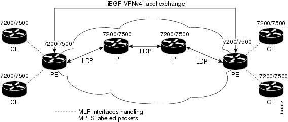
The PE-to-CE routing protocols that are supported for the MPLS--Multilink PPP Support feature are eBGP, OSPF, and EIGRP. Static routes are also supported between the CE and PE routers.
QoS features that are supported for the MPLS--Multilink PPP Support feature on CE-to-PE links are LFI, compressed Real-Time Transport Protocol (cRTP), policing, marking, and classification.
MPLS--Multilink PPP Support and Core Links
The figure below shows a sample topology in which MPLS is deployed over MLP on PE-to-P and P-to-P links. Enabling MPLS on MLP for PE-to-P links is similar to enabling MPLS on MLP for P-to-P links.

You employ MLP in the PE-to-P or P-to-P links primarily so that you can reduce the number of Interior Gateway Protocol (IGP) adjacencies and facilitate the load sharing of traffic.
In addition to requiring MLP on the PE-to-P links, the MPLS--Multilink PPP Support feature requires the configuration of an IGP routing protocol and LDP.
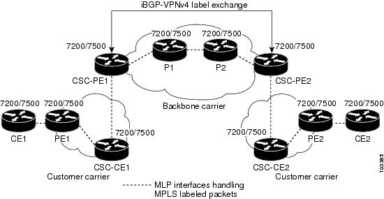
MPLS--Multilink PPP Support in a CSC Network
The figure below shows a typical MPLS VPN CSC network where MLP is configured on the CSC-CE-to-CSC-PE links.

The MPLS--Multilink PPP Support feature supports MLP between CSC-CE and CSC-PE links with LDP or with EBGP IPv4 label distribution. This feature also supports LFI for an MPLS VPN CSC configuration. The figure below shows all MLP links that this feature supports for CSC configurations.
MPLS--Multilink PPP Support in an Interautonomous System
The figure below shows a typical MPLS VPN interautonomous system (Inter-AS) network where MLP is configured on the PE-to-CE links.
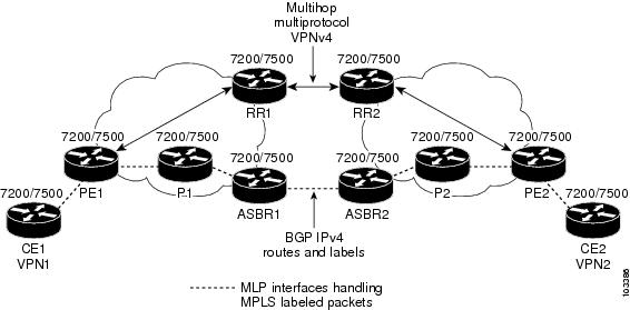
The MPLS--Multilink PPP Support feature supports MLP between ASBR links for Inter-AS VPNs with LDP and with eBGP IPv4 label distribution.
How to Configure MPLS--Multilink PPP Support
Service providers that use relatively low-speed links can use MLP to spread traffic across them in their MPLS networks. LFI should be deployed in the CE-to-PE link for efficiency, where traffic uses lower link bandwidth (less than 768 kbps). The MPLS--Multilink PPP Support feature can reduce the number of IGP adjacencies and facilitate load sharing of traffic.
The tasks in this section can be performed on CE-to-PE links, PE-to-P links, P-to-P links, and CSC CSC-CE-to-CSC-PE links.
- Enabling Cisco Express Forwarding or Distributed Cisco Express Forwarding Switching
- Creating a Multilink Bundle
- Assigning an Interface to a Multilink Bundle
- Disabling PPP Multilink Fragmentation
- Verifying the Multilink PPP Configuration
Enabling Cisco Express Forwarding or Distributed Cisco Express Forwarding Switching
Perform the following task to enable Cisco Express Forwarding or distributed Cisco Express Forwarding switching.
Multilink PPP requires the configuration of standard Cisco Express Forwarding. Distributed MLP (dMLP) requires the configuration of distributed Cisco Express Forwarding.
Cisco Express Forwarding is enabled by default on most Cisco platforms running Cisco IOS software Release12.0 or a later release. To find out if Cisco Express Forwarding is enabled on your platform, enter theshowipcefcommand. If Cisco Express Forwarding is enabled, you receive output that looks like this:
Router# show ip cef
Prefix              Next Hop            Interface
10.2.61.8/24        192.168.100.1       FastEthernet1/0/0
                    192.168.101.1       FastEthernet6/1
If Cisco Express Forwarding is not enabled on your platform, the output for the showipcefcommand looks like this:
Router# show ip cef
%CEF not running
Distributed Cisco Express Forwarding is enabled by default on devices such as the Catalyst 6500 series switch, the Cisco 7500 series router, and the Cisco 12000 series Internet router.
- ip cef
- ip cef distributed
DETAILED STEPS
Creating a Multilink Bundle
Perform this task to create a multilink bundle for the MPLS--Multilink PPP Support feature. This can reduce the number of IGP adjacencies and facilitate load sharing of traffic.
DETAILED STEPS
Assigning an Interface to a Multilink Bundle
Perform this task to assign an interface to a multilink bundle for the MPLS--Multilink PPP Support feature.
DETAILED STEPS
Disabling PPP Multilink Fragmentation
Perform this task to disable PPP multilink fragmentation. PPP multilink fragmentation is enabled by default.
Enabling fragmentation reduces the delay latency among bundle links, but adds some load to the CPU. Disabling fragmentation might produce better throughput.
If your data traffic is consistently of a similar size, we recommend disabling fragmentation. In this case, the benefits of fragmentation can be outweighed by the added load on the CPU.
DETAILED STEPS
Verifying the Multilink PPP Configuration
DETAILED STEPS
| Step 1 |
enable
Use this command to enable privileged EXEC mode. Enter your password if prompted. For example: Example:
Router> enable
Router#
|
| Step 2 |
show
ip
interface
brief
Use this command to verify logical and physical MLP interfaces. For example: Example:
Router# show ip interface brief
Locolrface                  IP-Address      OK? Method Status                Prot
FastEthernet1/0/0         10.3.62.106      YES NVRAM  up                    up
FastEthernet0/0/1          unassigned      YES NVRAM  administratively down down
FastEthernet0/0/0          unassigned      YES NVRAM  administratively down down
FastEthernet0/0/1          unassigned      YES NVRAM  administratively down down
FastEthernet0/0/2          unassigned      YES NVRAM  administratively down down
FastEthernet0/1/0          unassigned      YES NVRAM  administratively down down
FastEthernet0/1/1          unassigned      YES NVRAM  administratively down down
FastEthernet0/1/2          unassigned      YES NVRAM  administratively down down
FastEthernet1/2/0          unassigned      YES NVRAM  administratively down down
FastEthernet1/0/1          unassigned      YES NVRAM  administratively down down
FastEthernet1/1/0          unassigned      YES NVRAM  administratively down down
FastEthernet1/1/1          unassigned      YES NVRAM  administratively down down
FastEthernet1/1/2          unassigned      YES NVRAM  administratively down down
Serial1/1/0:1              unassigned      YES NVRAM  administratively down down
Serial1/1/0:2              unassigned      YES NVRAM  administratively down down
Serial1/1/1:1              unassigned      YES NVRAM  up                    up
Serial1/1/1:2              unassigned      YES NVRAM  up                    down
Serial1/1/3:1              unassigned      YES NVRAM  up                    up
Serial1/1/3:2              unassigned      YES NVRAM  up                    up
Multilink6                 10.30.0.2       YES NVRAM  up                    up
Multilink8                 unassigned      YES NVRAM  administratively down down
Multilink10                10.34.0.2       YES NVRAM  up                    up
Loopback0                  10.0.0.1        YES NVRAM  up                    up
|
| Step 3 |
show
ppp
multilink
Use this command to verify that you have created a multilink bundle. For example: Example:
Router# show ppp multilink
Multilink1, bundle name is group 1
 Bundle is Distributed
0 lost fragments, 0 reordered, 0 unassigned, sequence 0x0/0x0 rcvd/sent
0 discarded, 0 lost received, 1/255 load
Member links: 4 active, 0 inactive (max no set, min not set)
 Serial1/0/0/:1
 Serial1/0/0/:2
 Serial1/0/0/:3
 Serial1/0/0/:4
|
| Step 4 |
show
ppp
multilink
interface
interface-bundle
Use this command to display information about a specific MLP interface. For example: Example:
Router# show ppp multilink interface multilink6
Multilink6, bundle name is router
  Bundle up for 00:42:46, 1/255 load
  Receive buffer limit 24384 bytes, frag timeout 1524 ms
  Bundle is Distributed
    0/0 fragments/bytes in reassembly list
    1 lost fragments, 48 reordered
    0/0 discarded fragments/bytes, 0 lost received
    0x4D7 received sequence, 0x0 sent sequence
  Member links: 2 active, 0 inactive (max not set, min not set)
    Se1/1/3:1, since 00:42:46, 240 weight, 232 frag size
    Se1/1/3:2, since 00:42:46, 240 weight, 232 frag size
|
| Step 5 |
show
interface
interface-name
interface-number
Use this command to display information about serial interfaces in your configuration. For example: Example: Router# show interface serial 1/1/3:1 Serial1/1/3:1 is up, line protocol is up Hardware is Multichannel T1 MTU 1500 bytes, BW 64 Kbit, DLY 20000 usec, reliability 255/255, txload 1/255, rxload 1/255 Encapsulation PPP, LCP Open, multilink Open, crc 16, Data non-inverted Last input 00:00:01, output 00:00:01, output hang never Last clearing of "show interface" counters 00:47:13 Input queue: 0/75/0/0 (size/max/drops/flushes); Total output drops: 0 Queueing strategy: fifo Output queue: 0/40 (size/max) 5 minute input rate 0 bits/sec, 0 packets/sec 5 minute output rate 0 bits/sec, 0 packets/sec 722 packets input, 54323 bytes, 0 no buffer Received 0 broadcasts, 0 runts, 0 giants, 0 throttles 0 input errors, 0 CRC, 0 frame, 0 overrun, 0 ignored, 0 abort 697 packets output, 51888 bytes, 0 underruns 0 output errors, 0 collisions, 1 interface resets 0 output buffer failures, 0 output buffers swapped out 1 carrier transitions no alarm present Timeslot(s) Used:1, subrate: 64Kb/s, transmit delay is 0 flags Transmit queue length 25 Router# show interface serial 1/1/3:2 Serial1/1/3:2 is up, line protocol is up Hardware is Multichannel T1 MTU 1500 bytes, BW 64 Kbit, DLY 20000 usec, reliability 255/255, txload 1/255, rxload 1/255 Encapsulation PPP, LCP Open, multilink Open, crc 16, Data non-inverted Last input 00:00:03, output 00:00:03, output hang never Last clearing of "show interface" counters 00:47:16 Input queue: 0/75/0/0 (size/max/drops/flushes); Total output drops: 0 Queueing strategy: fifo Output queue: 0/40 (size/max) 5 minute input rate 0 bits/sec, 0 packets/sec 5 minute output rate 0 bits/sec, 0 packets/sec 725 packets input, 54618 bytes, 0 no buffer Received 0 broadcasts, 0 runts, 0 giants, 0 throttles 0 input errors, 0 CRC, 0 frame, 0 overrun, 0 ignored, 0 abort 693 packets output, 53180 bytes, 0 underruns 0 output errors, 0 collisions, 1 interface resets 0 output buffer failures, 0 output buffers swapped out 1 carrier transitions no alarm present Timeslot(s) Used:2, subrate: 64Kb/s, transmit delay is 0 flags Transmit queue length 26 You can also use the show interface command to display information about the multilink interface: Example:
Router# show interface multilink6
Multilink6 is up, line protocol is up
  Hardware is multilink group interface
  Internet address is 10.30.0.2/8
  MTU 1500 bytes, BW 128 Kbit, DLY 100000 usec,
     reliability 255/255, txload 1/255, rxload 1/255
  Encapsulation PPP, LCP Open, multilink Open
  Open: CDPCP, IPCP, TAGCP, loopback not set
  DTR is pulsed for 2 seconds on reset
  Last input 00:00:00, output never, output hang never
  Last clearing of "show interface" counters 00:48:43
  Input queue: 0/75/0/0 (size/max/drops/flushes); Total output drops: 0
  Queueing strategy: fifo
  Output queue: 0/40 (size/max)
  30 second input rate 0 bits/sec, 0 packets/sec
  30 second output rate 0 bits/sec, 0 packets/sec
     1340 packets input, 102245 bytes, 0 no buffer
     Received 0 broadcasts, 0 runts, 0 giants, 0 throttles
     0 input errors, 0 CRC, 0 frame, 0 overrun, 0 ignored, 0 abort
     1283 packets output, 101350 bytes, 0 underruns
     0 output errors, 0 collisions, 1 interface resets
     0 output buffer failures, 0 output buffers swapped out
     0 carrier transitions
|
| Step 6 |
show
mpls
forwarding-table
Use this command to display contents of the MPLS Label Forwarding Information Base (LFIB) and look for information on multilink interfaces associated with a point2point next hop. For example: Example:
Router# show mpls forwarding-table
Local  Outgoing    Prefix            Bytes tag  Outgoing   Next Hop
tag    tag or VC   or Tunnel Id      switched   interface
16     Untagged    10.30.0.1/32      0          Mu6        point2point
17     Pop tag     10.0.0.3/32       0          Mu6        point2point
18     Untagged    10.0.0.9/32[V]    0          Mu10       point2point
19     Untagged    10.0.0.11/32[V]   6890       Mu10       point2point
20     Untagged    10.32.0.0/8[V]    530        Mu10       point2point
21     Aggregate   10.34.0.0/8[V]    0
22     Untagged    10.34.0.1/32[V]   0          Mu10       point2point
Use the show ip bgp vpnv4command to display VPN address information from the Border Gateway Protocol (BGP) table: Example:
Router# show ip bgp vpnv4 all summary
BGP router identifier 10.0.0.1, local AS number 100
BGP table version is 21, main routing table version 21
10 network entries using 1210 bytes of memory
10 path entries using 640 bytes of memory
2 BGP path attribute entries using 120 bytes of memory
1 BGP extended community entries using 24 bytes of memory
0 BGP route-map cache entries using 0 bytes of memory
0 BGP filter-list cache entries using 0 bytes of memory
BGP using 1994 total bytes of memory
BGP activity 10/0 prefixes, 10/0 paths, scan interval 5 secs
10.0.0.3  4 100 MsgRc52 MsgSe52  TblV21  0  0 00:46:35 State/P5xRcd
|
| Step 7 |
exit
Use this command to exit to user EXEC mode. For example: Example:
Router# exit
Router>
|
Configuration Examples for MPLS--Multilink PPP Support
- Sample MPLS--Multilink PPP Support Configurations
- Enabling Cisco Express Forwarding or Distributed Cisco Express Forwarding Example
- Creating a Multilink Bundle Example
- Assigning an Interface to a Multilink Bundle Example
Sample MPLS--Multilink PPP Support Configurations
The following examples show sample configurations for MLP on a Cisco 7200 router, on a Cisco 7500 router, and on a CSC network. The configuration of MLP on an interface is the same for PE-to-CE links, PE-to-P links, and P-to-P links.
- Sample Multilink PPP Configuration on Cisco 7200 Series Router
- Sample Multilink PPP Configuration for Cisco 7500 Series Router
- Sample Multilink PPP Configuration on an MPLS CSC PE Router
Sample Multilink PPP Configuration on Cisco 7200 Series Router
Following is a sample configuration of a Cisco 7200 router, which is connected with a T1 line card and configured with an MPLS Multilink PPP interface:
controller T1 1/3
 framing esf
 clock source internal
 linecode b8zs
 channel-group 1 timeslots 1
 channel-group 2 timeslots 2
 no yellow generation
 no yellow detection
!
interface Multilink6
 ip address 10.37.0.1 255.0.0.0
 ppp multilink interleave
 tag-switching ip
 load-interval 30
 multilink-group 6
!
interface Serial1/3:1
 encapsulation ppp
 no ip address
 ppp multilink
 tx-queue-limit 26
 multilink-group 6
 peer neighbor-route
!
interface Serial1/3:2
 encapsulation ppp
 no ip address
 ppp multilink
 tx-queue-limit 26
 multilink-group 6
 peer neighbor-route
Sample Multilink PPP Configuration for Cisco 7500 Series Router
Following is a sample configuration of a Cisco 7500 router, which is connected with a T1 line card and configured with an MPLS Multilink PPP interface:
controller T1 1/1/3
 framing esf
 clock source internal
 linecode b8zs
 channel-group 1 timeslots 1
 channel-group 2 timeslots 2
 no yellow generation
 no yellow detection
!
interface Multilink6
 ip address 10.37.0.2 255.0.0.0
 ppp multilink interleave
 tag-switching ip
 load-interval 30
 multilink-group 6
!
interface Serial1/1/3:1
 encapsulation ppp
 no ip address
 ppp multilink
 tx-queue-limit 26
 multilink-group 6
 peer neighbor-route
!
interface Serial1/1/3:2
 encapsulation ppp
 no ip address
 ppp multilink
 tx-queue-limit 26
 multilink-group 6
 peer neighbor-route
Sample Multilink PPP Configuration on an MPLS CSC PE Router
Following is a sample configuration for an MPLS CSC PE router. An EBGP session is configured between the PE and CE routers.
PE-Router# show running-config interface Serial1/0:1
Building configuration...
!
mpls label protocol ldp
ip cef
ip vrf vpn2
 rd 200:1
 route-target export 200:1
 route-target import 200:1
!
controller T1 1/0
 framing esf
 clock source internal
 linecode b8zs
 channel-group 1 timeslots 1
 channel-group 2 timeslots 2
 no yellow generation
 no yellow detection
!
interface Serial1/0:1
 no ip address
 encapsulation ppp
 tx-ring-limit 26
 ppp multilink
 ppp multilink group 1
!
interface Serial1/0:2
 no ip address
 encapsulation ppp
 tx-ring-limit 26
 ppp multilink
 ppp multilink group 1
!
interface Multilink1
 ip vrf forwarding vpn2
 ip address 10.35.0.2 255.0.0.0
 no peer neighbor-route
 load-interval 30
 ppp multilink
 ppp multilink interleave
 ppp multilink group 1
!
!
router ospf 200
 log-adjacency-changes
 auto-cost reference-bandwidth 1000
 redistribute connected subnets
 passive-interface Multilink1
 network 10.0.0.7 0.0.0.0 area 200
 network 10.31.0.0 0.255.255.255 area 200
!
!
 router bgp 200
 no bgp default ipv4-unicast
 bgp log-neighbor-changes
 neighbor 10.0.0.11 remote-as 200
 neighbor 10.0.0.11 update-source Loopback0
 !
 address-family vpnv4
 neighbor 10.0.0.11 activate
 neighbor 10.0.0.11 send-community extended
 bgp scan-time import 5
 exit-address-family
 !
 address-family ipv4 vrf vpn2
 redistribute connected
 neighbor 10.35.0.1 remote-as 300
 neighbor 10.35.0.1 activate
 neighbor 10.35.0.1 as-override
 neighbor 10.35.0.1 advertisement-interval 5
 no auto-summary
 no synchronization
 exit-address-family
Assigning an Interface to a Multilink Bundle Example
The following example shows how to create four multilink interfaces with distributed Cisco Express Forwarding switching and MLP enabled. Each of the newly created interfaces is added to a multilink bundle.
interface multilink1
 ip address 10.0.0.0 10.255.255.255
 ppp chap hostname group 1
 ppp multilink
 multilink-group 1

interface serial 1/0/0/:1
 no ip address
 encapsulation ppp
 ip route-cache distributed
 no keepalive
 ppp multilink
 multilink-group 1
interface serial 1/0/0/:2
 no ip address
 encapsulation ppp
 ip route-cache distributed
 no keepalive
 ppp chap hostname group 1
 ppp multilink
 multilink-group 1
interface serial 1/0/0/:3
 no ip address
 encapsulation ppp
 ip route-cache distributed
 no keepalive
 ppp chap hostname group 1
 ppp multilink
 multilink-group 1
interface serial 1/0/0/:4
 no ip address
 encapsulation ppp
 ip route-cache distributed
 no keepalive
 ppp chap hostname group 1
 ppp multilink
 multilink-group
Additional References
Related Documents
|
Related Topic |
Document Title |
|---|---|
|
Configuration tasks for Distributed MLP for Cisco 7500 series routers |
Distributed Multilink Point-to-Point Protocol for Cisco 7500 Series Routers |
|
Configuration tasks for media-independent PPP and Multilink PPP |
|
|
Configuration tasks for MPLS DiffServ tunneling modes |
|
|
Configuration tasks for the MPLS QoS multi-VC mode feature |
"Configuring MPLS" chapter, Cisco IOS Multiprotocol Label Switching Configuration Guide , Release 12.4 |
|
Configuration tasks for MPLS VPNs |
"MPLS Virtual Private Networks" chapter, Cisco IOS Multiprotocol Label Switching Configuration Guid e, Release 12.4 |
|
Configuration tasks for MPLS VPN CSC |
"MPLS Virtual Private Networks" chapter, Cisco IOS Multiprotocol Label Switching Configuration Guid e, Release 12.4 |
|
Configuration tasks for MPLS VPN CSC with IPv4 BGP label distribution |
"MPLS Virtual Private Networks" chapter, Cisco IOS Multiprotocol Label Switching Configuration Guid e, Release 12.4 |
|
Configuration tasks for MPLS VPN Inter-AS with IPv4 BGP label distribution |
"MPLS Virtual Private Networks" chapter, Cisco IOS Multiprotocol Label Switching Configuration Guid e, Release 12.4 |
MIBs
Technical Assistance
Feature Information for MPLS--Multilink PPP Support
The following table provides release information about the feature or features described in this module. This table lists only the software release that introduced support for a given feature in a given software release train. Unless noted otherwise, subsequent releases of that software release train also support that feature.
Use Cisco Feature Navigator to find information about platform support and Cisco software image support. To access Cisco Feature Navigator, go to www.cisco.com/go/cfn. An account on Cisco.com is not required.
| Table 5 | Feature Information for MPLS--Multilink PPP Support |
|
Feature Name |
Releases |
Feature Information |
|---|---|---|
|
MPLS--Multilink PPP Support |
12.2(8)T 12.2(15)T1012.3(5a) 12.3(7)T 12.2(28)SB 12.4(20)T |
The MPLS--Multilink PPP Support feature ensures that MPLS Layer 3 Virtual Private Networks (VPNs) with quality of service (QoS) can be enabled for bundled links. This feature supports Multiprotocol Label Switching (MPLS) over Multilink PPP (MLP) links in the edge (provider edge [PE]-to-customer edge [CE]) or in the MPLS core (PE-to-PE and PE-to-provider router [P]). Service providers that use relatively low-speed links can use MLP to spread traffic across them in their MPLS networks. Link fragmentation and interleaving (LFI) should be deployed in the CE-to-PE link for efficiency, where traffic uses a lower link bandwidth (less than 768 kbps). In 12.2(8)T, MLP support on CE-to-PE links was introduced. In 12.2(15)T10 and 12.3(5a), MLP support for MPLS networks was extended to PE-to-P links, PE-to-PE links, Carrier Supporting Carrier (CSC) CSC-CE-to-CSC-PE links, and interautonomous system (Inter-AS) PE-to-PE links. In 12.3(7)T, the feature was integrated into the Cisco IOS 12.3T release. In 12.2(28)SB, the feature was integrated into the Cisco IOS 12.2SB release. In 12.4(20)T, the feature was integrated into the Cisco IOS 12.4T release. |
Glossary
bundle --A group of interfaces connected by parallel links between two systems that have agreed to use Multilink PPP (MLP) over those links.
CBWFQ --class-based weighted fair queueing. A queueing option that extends the standard Weighted Fair Queueing (WFQ) functionality to provide support for user-defined traffic classes.
Cisco Express Forwarding --A proprietary form of switching that optimizes network performance and scalability for networks with large and dynamic traffic patterns, such as the Internet, and for networks characterized by intensive web-based applications or interactive sessions. Although you can use Cisco Express Forwarding in any part of a network, it is designed for high-performance, highly resilient Layer 3 IP backbone switching.
EIGRP --Enhanced Interior Gateway Routing Protocol. An advanced version of the Interior Gateway Routing Protocol (IGRP) developed by Cisco. It provides superior convergence properties and operating efficiency, and combines the advantages of link-state protocols with those of distance vector protocols.
IGP --Interior Gateway Protocol. An Internet protocol used to exchange routing information within an autonomous system. Examples of common Internet IGPs include Interior Gateway Routing Protocol (IGRP), Open Shortest Path First (OSPF), and Routing Information Protocol (RIP).
IGRP --Interior Gateway Routing Protocol. An Interior Gateway Protocol (IGP) developed by Cisco to address the issues associated with routing in large, heterogeneous networks. Compare with Enhanced Interior Gateway Routing Protocol (EIGRP).
IS-IS --Intermediate System-to-Intermediate System. An Open Systems Interconnection (OSI) link-state hierarchical routing protocol, based on DECnet Phase V routing, in which IS-IS routers exchange routing information based on a single metric to determine network topology.
LCP --Link Control Protocol. A protocol that establishes, configures, and tests data link connections for use by PPP.
LFI --link fragmentation and interleaving. The Cisco IOS XE LFI feature reduces delay on slower-speed links by breaking up large datagrams and interleaving low-delay traffic packets with the smaller packets resulting from the fragmented datagram. LFI allows reserve queues to be set up so that Real-Time Protocol (RTP) streams can be mapped into a higher priority queue in the configured weighted fair queue set.
link --One of the interfaces in a bundle.
LLQ --low latency queueing. A quality of service QoS queueing feature that provides a strict priority queue (PQ) for voice traffic and weighted fair queues for other classes of traffic. It is also called priority queueing/class-based weighted fair queueing (PQ/CBWFQ).
MLP --Multilink PPP. A method of splitting, recombining, and sequencing datagrams across multiple logical links. The use of MLP increases throughput between two sites by grouping interfaces and then load balancing packets over the grouped interfaces (called a bundle). Splitting packets at one end, sending them over the bundled interfaces, and recombining them at the other end achieves load balancing.
MQC --Modular QoS CLI. MQC is a CLI structure that allows users to create traffic polices and attach these polices to interfaces. MQC allows users to specify a traffic class independently of QoS policies.
NCP --Network Control Protocol. A series of protocols for establishing and configuring different network layer protocols (such as for AppleTalk) over PPP.
OSPF --Open Shortest Path First. A link-state, hierarchical Interior Gateway Protocol (IGP) routing algorithm proposed as a successor to Routing Information Protocol (RIP) in the Internet community. OSPF features include least-cost routing, multipath routing, and load balancing. OSPF was derived from an early version of the IS-IS protocol.
PPP --Point-to-Point Protocol. A successor to the Serial Line Interface Protocol (SLIP) that provides router-to-router and host-to-network connections over synchronous and asynchronous circuits. PPP works with several network layer protocols (such as IP, Internetwork Packet Exchange [IPX], and AppleTalk Remote Access [ARA]). PPP also has built-in security mechanisms (such as Challenge Handshake Authentication Protocol [CHAP] and Password Authentication Protocol [PAP]). PPP relies on two protocols: Link Control Protocol (LCP) and Network Control Protocol (NCP).
RIP --Routing Information Protocol. A version of Interior Gateway Protocol (IGP) that is supplied with UNIX Berkeley Standard Distribution (BSD) systems. Routing Information Protocol (RIP) is the most common IGP in the Internet. It uses hop count as a routing metric.
Virtual Bundle Interface --An interface that represents the master link of a bundle. It is not tied to any physical interface. Data going over the bundle is transmitted and received through the master link.
WFQ --weighted fair queueing. A congestion management algorithm that identifies conversations (in the form of traffic streams), separates packets that belong to each conversation, and ensures that capacity is shared fairly among the individual conversations. WFQ is an automatic way of stabilizing network behavior during congestion and results in improved performance and reduced retransmission.
WRED --weighted random early detection. A queueing method that ensures that high-precedence traffic has lower loss rates than other traffic during times of congestion.
Cisco and the Cisco logo are trademarks or registered trademarks of Cisco and/or its affiliates in the U.S. and other countries. To view a list of Cisco trademarks, go to this URL: www.cisco.com/go/trademarks. Third-party trademarks mentioned are the property of their respective owners. The use of the word partner does not imply a partnership relationship between Cisco and any other company. (1110R)
Any Internet Protocol (IP) addresses and phone numbers used in this document are not intended to be actual addresses and phone numbers. Any examples, command display output, network topology diagrams, and other figures included in the document are shown for illustrative purposes only. Any use of actual IP addresses or phone numbers in illustrative content is unintentional and coincidental.