
 Feedback
Contents
- Resilient Ethernet Protocol
- Finding Feature Information
- Information About REP
- REP Segments
- Link Integrity
- Fast Convergence
- VLAN Load Balancing
- Spanning Tree Protocol Interaction
- REP Ports
- REP Integrated with VPLS
- Default REP Configuration
- REP Segments and REP Administrative VLANs
- REP Configuration Guidelines
- REP Support on Trunk EFP
- How to Configure REP
- Configuring the REP Administrative VLAN
- Guidelines for Configuring the REP Administrative VLAN
- Configuring REP on Trunk EFP
- Setting the Preemption for VLAN Load Balancing
- Restrictions
- Configuring SNMP Traps for REP
- Monitoring the REP Configuration
- Configuration Examples for REP
- Example Configuring the REP Administrative VLAN
- Example Configuring REP Support on Trunk EFP
- Example Setting the Preemption for VLAN Load Balancing
- Example Configuring SNMP Traps for REP
- Example Monitoring the REP Configuration
- Additional References
- Additional References
- Feature Information for Resilient Ethernet Protocol
Resilient Ethernet Protocol
Resilient Ethernet Protocol (REP) is a Cisco proprietary protocol that provides an alternative to Spanning Tree Protocol (STP). REP provides a way to control network loops, handle link failures, and improve convergence time. REP controls a group of ports connected in a segment, ensures that the segment does not create any bridging loops, and responds to link failures within the segment. REP provides a basis for constructing more complex networks and supports VLAN load balancing.
The router supports REP only when the router is running the metro IP access or metro access image.
Finding Feature Information
Your software release may not support all the features documented in this module. For the latest feature information and caveats, see the release notes for your platform and software release. To find information about the features documented in this module, and to see a list of the releases in which each feature is supported, see the Feature Information Table at the end of this document.
Use Cisco Feature Navigator to find information about platform support and Cisco software image support. To access Cisco Feature Navigator, go to www.cisco.com/go/cfn. An account on Cisco.com is not required.
Information About REP
- REP Segments
- Link Integrity
- Fast Convergence
- VLAN Load Balancing
- Spanning Tree Protocol Interaction
- REP Ports
- REP Integrated with VPLS
- Default REP Configuration
- REP Segments and REP Administrative VLANs
- REP Configuration Guidelines
- REP Support on Trunk EFP
REP Segments
One REP segment is a chain of ports connected to each other and configured with a segment ID. Each segment consists of standard (non-edge) segment ports and two user-configured edge ports. A router can have no more than two ports that belong to the same segment, and each segment port can have only one external neighbor. A segment can go through a shared medium, but on any link only two ports can belong to the same segment. REP is supported only on Trunk EFP interfaces.
The figure below shows an example of a segment consisting of six ports spread across four switches. Ports E1 and E2 are configured as edge ports. When all ports are operational (as in the segment on the left), a single port is blocked, shown by the diagonal line. When there is a failure in the network, the blocked port returns to the forwarding state to minimize network disruption.
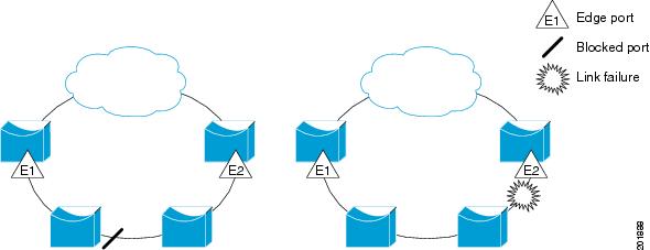
The segment shown in the figure above is an open segment; there is no connectivity between the two edge ports. The REP segment cannot cause a bridging loop and it is safe to connect the segment edges to any network. All hosts connected to routers inside the segment have two possible connections to the rest of the network through the edge ports, but only one connection is accessible at any time. If a failure occurs on any segment or any port on a REP segment, REP unblocks all ports to ensure that connectivity is available through the other gateway.
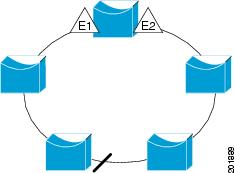
The segment shown in the figure below, with both edge ports located on the same router, is a ring segment. In this configuration, there is connectivity between the edge ports through the segment. With this configuration, you can create a redundant connection between any two routers in the segment.
REP segments have the following characteristics:
- If all ports in the segment are operational, one port (referred to as the alternate port) is in the blocked state for each VLAN. If VLAN load balancing is configured, two ports in the segment control the blocked state of VLANs.
- If one or more ports in a segment is not operational, causing a link failure, all ports forward traffic on all VLANs to ensure connectivity.
- In case of a link failure, the alternate ports are unblocked as quickly as possible. When the failed link comes back up, a logically blocked port-per VLAN is selected with minimal disruption to the network.
You can construct almost any type of network based on REP segments. REP also supports VLAN load balancing, controlled by the primary edge port but occurring at any port in the segment.
REP has the following limitations:
- You must configure each segment port; an incorrect configuration can cause forwarding loops in the networks.
- REP can manage only a single failed port within the segment; multiple port failures within the REP segment causes loss of network connectivity.
- You should configure REP only in networks with redundancy. Configuring REP in a network without redundancy causes loss of connectivity.
Link Integrity
REP does not use an end-to-end polling mechanism between edge ports to verify link integrity. It implements local link failure detection. When enabled on an interface, the REP Link Status Layer (LSL) detects its REP-aware neighbor and establishes connectivity within the segment. All VLANs are blocked on an interface until it detects the neighbor. After the neighbor is identified, REP determines which neighbor port should become the alternate port and which ports should forward traffic.
Each port in a segment has a unique port ID. The port ID format is similar to that used by the spanning tree algorithm: a port number (unique on the bridge), associated to a MAC address (unique in the network). When a segment port is coming up, its LSL starts sending packets that include the segment ID and the port ID. The port is declared as operational after it performs a three-way handshake with a neighbor in the same segment. A segment port does not become operational under the following conditions:
- No neighbor has the same segment ID.
- More than one neighbor has the same segment ID.
- The neighbor does not acknowledge the local port as a peer.
Each port creates an adjacency with its immediate neighbor. Once the neighbor adjacencies are created, the ports negotiate to determine one blocked port for the segment, the alternate port. All other ports become unblocked. By default, REP packets are sent to a PortFast Bridge Protocol Data Unit (BPDU) class MAC address. The packets can also be sent to the Cisco multicast address, which at present is used only to send blocked port advertisement (BPA) messages when there is a failure in the segment. The packets are dropped by devices not running REP.
Fast Convergence
Because REP runs on a physical-link basis and not a per-VLAN basis, only one hello message is required for all VLANs, reducing the load on the protocol. We recommend that you create VLANs consistently on all switches in a given segment and configure the same allowed VLANs on the REP trunk ports. To avoid the delay introduced by relaying messages in software, REP also allows some packets to be flooded to a regular multicast address. These messages operate at the hardware flood layer (HFL) and are flooded to the whole network, not just the REP segment. Switches that do not belong to the segment treat the messages as data traffic. You can control flooding of these messages by configuring a dedicated administrative VLAN for the whole domain.
The estimated convergence recovery time is less than 200 milliseconds (ms) for the local segment.
VLAN Load Balancing
One edge port in the REP segment acts as the primary edge port; the other as the secondary edge port. It is the primary edge port that always participates in VLAN load balancing in the segment. REP VLAN load balancing is achieved by blocking some VLANs at a configured alternate port and all other VLANs at the primary edge port. When you configure VLAN load balancing, you can specify the alternate port in one of three ways:
- By entering the port ID of the interface. To identify the port ID of a port in the segment, enter the show interface rep detail command for the port.
- By entering the neighbor offset number of a port in the segment, which identifies the downstream neighbor port of an edge port. The neighbor offset number range is -256 to +256; a value of 0 is invalid. The primary edge port has an offset number of 1; positive numbers above 1 identify downstream neighbors of the primary edge port. Negative numbers indicate the secondary edge port (offset number -1) and its downstream neighbors.
- By entering the preferred keyword to select the port that you previously configured as the preferred alternate port with the rep segment segment-id preferred command.
When the REP segment is complete, all VLANs are blocked. When you configure VLAN load balancing, it is triggered in one of two ways:
- You can manually trigger VLAN load balancing at any time by entering the rep preempt segment segment-id command on the router that has the primary edge port.
- You can configure a preempt delay time by entering the rep preempt delay secondscommand. After a link failure and recovery, VLAN load balancing begins after the configured preemption time period elapses. Note that the delay timer restarts if another port fails before the time has elapsed.
 Note | When VLAN load balancing is configured, it does not start working until triggered by either manual intervention or a link failure and recovery. |
When VLAN load balancing is triggered, the primary edge port then sends out a message to alert all interfaces in the segment about the preemption. When the message is received by the secondary edge port, it is reflected into the network to notify the alternate port to block the set of VLANs specified in the message and to notify the primary edge port to block the remaining VLANs.
You can also configure a particular port in the segment to block all VLANs. VLAN load balancing is initiated only by the primary edge port and is not possible if the segment is not terminated by an edge port on each end. The primary edge port determines the local VLAN load balancing configuration.
To reconfigure VLAN load balancing, you reconfigure the primary edge port. When you change the VLAN-load balancing configuration, the primary edge port again waits for the rep preempt segmentcommand or for the configured preempt delay period after a port failure and recovery before executing the new VLAN load balancing configuration. If you change an edge port to a regular segment port, the existing VLAN load balancing status does not change. Configuring a new edge port might cause a new topology configuration.
Spanning Tree Protocol Interaction
REP does not interact with Spanning Tree Protocol (STP) or with Flex Links, but can coexist with both of them. A port that belongs to a segment is removed from spanning tree control and STP BPDUs are not accepted or sent from segment ports. Therefore, STP cannot run on a segment.
To migrate from an STP ring configuration to REP segment configuration, begin by configuring a single port in the ring as part of the segment and continue by configuring contiguous ports to minimize the number of segments. Each segment always contains a blocked port, so multiple segments means multiple blocked ports and a potential loss of connectivity. When the segment has been configured in both directions up to the location of the edge ports, you then configure the edge ports.
REP Ports
Ports in REP segments take one of three roles or states: Failed, Open, or Alternate.
- A port configured as a regular segment port starts as a failed port.
- Once the neighbor adjacencies are determined, the port transitions to alternate port state, blocking all VLANs on the interface. Blocked port negotiations occur and when the segment settles, one blocked port remains in the alternate role and all other ports become open ports.
- When a failure occurs in a link, all ports move to the failed state. When the alternate port receives the failure notification, it changes to the open state, forwarding all VLANs.
A regular segment port converted to an edge port, or an edge port converted to a regular segment port, does not always result in a topology change. If you convert an edge port into a regular segment port, VLAN load balancing is not implemented unless it has been configured. For VLAN load balancing, you must configure two edge ports in the segment.
A segment port that is reconfigured as a spanning tree port restarts according to the spanning tree configuration. By default, this is a designated blocking port. If the PortFast BPDU Guard Enhancement feature is configured or if STP is disabled, the port goes into the forwarding state.
REP Integrated with VPLS
Normally, in a Virtual Private LAN Services (VPLS) network core, all nodes are connected in a full-mesh topology and each node has connectivity to all other nodes. In the full-mesh topology, there is no need for a node to retransmit data to another node. In Figure 3, the common ring provides a path where the packet could be forwarded to another network provider edge (N-PE) router, breaking the split horizon model.
REP emulates a common link connection that so that the REP ring supports the VPLS full-mesh model, but maintains the split horizon properties so that the super-loop does not exist. The emulated common link uses the Clustering over the WAN (CWAN) line card, which is also used for the VPLS uplink. This emulated common link forwards data from the ring to either the VPLS uplink or to the other side of the ring; blocks data coming from the VPLS core network; handles access pseudo-wire for H-VPLS topologies.
Default REP Configuration
REP is disabled on all interfaces. When enabled, the interface is a regular segment port unless it is configured as an edge port.
When REP is enabled, the sending of segment topology change notices (STCNs) is disabled, all VLANs are blocked, and the administrative VLAN is VLAN 1.
When VLAN load balancing is enabled, the default is manual preemption with the delay timer disabled. If VLAN load balancing is not configured, the default after manual preemption is to block all VLANs at the primary edge port.
REP Segments and REP Administrative VLANs
A segment is a collection of ports connected one to the other in a chain and configured with a segment ID. To configure REP segments, you should configure the REP administrative VLAN (or use the default VLAN 1) and then add the ports to the segment using interface configuration mode. You should configure two edge ports in the segment, with one of them the primary edge port and the other by default the secondary edge port. A segment has only one primary edge port. If you configure two ports in a segment as the primary edge port, for example ports on different switches, the REP selects one of them to serve as the segment primary edge port. You can also optionally configure where to send segment STCNs and VLAN load balancing. For more information about configuring REP Administrative VLANS, see the Configuring the REP Administrative VLAN.
REP Configuration Guidelines
Follow these guidelines when configuring REP:
- Cisco recommends that you begin by configuring one port and then configure the contiguous ports to minimize the number of segments and the number of blocked ports.
- If more than two ports in a segment fail when no external neighbors are configured, one port goes into a forwarding state for the data path to help maintain connectivity during configuration. In the show rep interface command output, the Port Role for this port shows as Fail Logical Open ; the Port Role for the other failed port shows as Fail No Ext Neighbor . When the external neighbors for the failed ports are configured, the ports go through the alternate port state transitions and eventually go to an open state or remain as the alternate port, based on the alternate port election mechanism.
- REP ports must be Layer 2 IEEE 802.1Q or trunk EFP ports.
- You must configure all trunk ports in the segment with the same set of allowed VLANs, or a misconfiguration occurs.
- Be careful when configuring REP through a Telnet connection. Because REP blocks all VLANs until another REP interface sends a message to unblock it, you might lose connectivity to the router if you enable REP in a Telnet session that accesses the router through the same interface.
- You cannot run REP and STP on the same segment or interface.
- If you connect an STP network to the REP segment, be sure that the connection is at the segment edge. An STP connection that is not at the edge could cause a bridging loop because STP does not run on REP segments. All STP BPDUs are dropped at REP interfaces.
- If REP is enabled on two ports on a router, both ports must be either regular segment ports or edge ports. REP ports follow these rules:
- If only one port on a router is configured in a segment, the port should be an edge port.
- If two ports on a router belong to the same segment, both ports must be edge ports or both ports must be regular segment ports.
- If two ports on a router belong to the same segment and one is configured as an edge port and one as a regular segment port (a misconfiguration), the edge port is treated as a regular segment port.
- REP interfaces come up in a blocked state and remains in a blocked state until notified that it is safe to unblock. You need to be aware of this to avoid sudden connection losses.
- REP ports can not be configured as one of these port types:
- There is a maximum of 22 REP segments per router.
REP Support on Trunk EFP
Resilient Ethernet Protocol (REP) can be configured on Trunk Ethernet Flow Point (EFP )ports at interface level on ASR 903 Series Routers. Trunk EFP ports can have several bridged Vlan services running on them. Vlans can be set as blocking and forwarding state on a Trunk EFP port. A user must enable REP on a port. By default, REP is disabled on all ports.
How to Configure REP
- Configuring the REP Administrative VLAN
- Configuring REP on Trunk EFP
- Setting the Preemption for VLAN Load Balancing
- Configuring SNMP Traps for REP
- Monitoring the REP Configuration
Configuring the REP Administrative VLAN
To configure the REP administrative VLAN, complete the following steps:
Guidelines for Configuring the REP Administrative VLAN
To avoid the delay introduced by relaying messages related to link-failure or VLAN-blocking notification during VLAN load balancing, REP floods packets at the hardware flood layer (HFL) to a regular multicast address. These messages are flooded to the whole network, not just the REP segment. You can control flooding of these messages by configuring an administrative VLAN for the whole domain.
Follow these guidelines when configuring the REP administrative VLAN:
- If you do not configure an administrative VLAN, the default is VLAN 1.
- There can be only one administrative VLAN on a router and on a segment. However, this is not enforced by the software.
- If you want to configure REP on an interface, ensure that the REP administrative VLAN is a part of the Trunk EFP encapsulation list .
DETAILED STEPS
Configuring REP on Trunk EFP
For REP operation, you need to enable it on each segment interface and identify the segment ID. This step is required and must be done before other REP configurations. You must also configure a primary and secondary edge port on each segment. All other steps are optional.
DETAILED STEPS
Setting the Preemption for VLAN Load Balancing
To set the preemption for VLAN load balancing, complete these steps on the router that has the segment with the primary edge port.
Restrictions
If you do not enter the rep preempt delay seconds interface configuration command on the primary edge port to configure a preemption time delay, the default is to manually trigger VLAN load balancing on the segment. Use the show rep topologyprivileged EXEC command to see which port in the segment is the primary edge port.
Be sure that all other segment configuration has been completed before setting preemption for VLAN load balancing. When you enter the rep preempt segment segment-id command, a confirmation message appears before the command is executed because preemption for VLAN load balancing can disrupt the network.
DETAILED STEPS
| Command or Action | Purpose | |||
|---|---|---|---|---|
Step 1 |
enable
Example: Router> enable |
Enables privileged EXEC mode.
| ||
Step 2 |
configure
terminal
Example: Router# configure terminal |
Enters global configuration mode. | ||
Step 3 |
rep
preempt
segment
segment-id
Example: Router(config)# rep preempt segment 1 |
Manually triggers VLAN load balancing on the segment.
| ||
Step 4 |
end
Example: Router(config)# end |
Returns to privileged EXEC mode. | ||
Step 5 |
show
rep
topology
Example: Router# show rep topology |
Views the REP topology information. |
Configuring SNMP Traps for REP
You can configure the router to send REP-specific traps to notify the SNMP server of link operational status changes and any port role changes. To configure REP traps, complete the following steps:
DETAILED STEPS
| Command or Action | Purpose | |||
|---|---|---|---|---|
Step 1 |
enable
Example: Router> enable |
Enables privileged EXEC mode.
| ||
Step 2 |
configure
terminal
Example: Router# configure terminal |
Enters global configuration mode. | ||
Step 3 |
snmp
mib
rep
trap-rate
value
Example: Router(config)# snmp mib rep trap-rate 500 |
Enables the router to send REP traps, and sets the number of traps sent per second.
| ||
Step 4 |
end
Example: Router(config)# end |
Returns to privileged EXEC mode. | ||
Step 5 |
show
running-config
Example: Router# show running-config |
(Optional) Displays the running configuration, which you can use to verify the REP trap configuration. | ||
Step 6 |
copy
running-config
startup
config
Example: Router# copy running-config startup config |
(Optional) Saves your entries in the router startup configuration file. |
Monitoring the REP Configuration
DETAILED STEPS
| Command or Action | Purpose | |
|---|---|---|
Step 1 |
enable
Example: Router> enable |
Enables privileged EXEC mode.
|
Step 2 |
show
interface
[interface-id] rep [detail] Example: Router# show interface gigabitethernet0/1 rep detail |
(Optional) Displays the REP configuration and status for a specified interface.
|
Step 3 |
show
rep
topology
[segment segment-id] [archive] [detail] Example: Router# show rep topology |
(Optional) Displays REP topology information for a segment or for all segments, including the primary and secondary edge ports in the segment.
|
Configuration Examples for REP
- Example Configuring the REP Administrative VLAN
- Example Configuring REP Support on Trunk EFP
- Example Setting the Preemption for VLAN Load Balancing
- Example Configuring SNMP Traps for REP
- Example Monitoring the REP Configuration
- Additional References
Example Configuring REP Support on Trunk EFP
This example shows how to configure REP support on Trunk EFP. An interface is configured as the primary edge port for segment 1, to send STCNs to segments 2 through 5, and the alternate port is configured as the port with port ID 0009001818D68700 to block all VLANs after a preemption delay of 60 seconds after a segment port failure and recovery.
Router# configure terminal
Router(config)# interface gigabitethernet0/0/1
Router(config-if)# rep segment 1 edge primary
 Router(config-if)# rep stcn segment 2-5
Router(config-if)# rep block port id 0009001818D68700 vlan all
Router(config-if)# rep preempt delay 60
Router(config-if)#service instance trunk 1 ethernet
Router(config-if-srv)#encapsulation dot1q
Router(config-if-srv)#rewrite ingress tag pop 1 symmetric
Router(config-if-srv)#bridge-domain from-encapsulation
Router(config-if)# end
This example shows how to configure the VLAN blocking configuration shown in the figure below. The alternate port is the neighbor with neighbor offset number 4. After manual preemption, VLANs 100 to 200 are blocked at this port and all other VLANs are blocked at the primary edge port E1 (Gigabit Ethernet port 0/0/1).
Router# configure terminal
Router(config)# interface gigabitethernet0/0/1
Router(config-if)# rep segment 1 edge primary
Router(config-if)# rep block port 4 vlan 100-200
Router(config-if)# end

Example Monitoring the REP Configuration
The following is sample output of the show interface rep detail command. Use the show interface rep detail command on one of the REP interfaces to monitor and verify the REP configuration.
Router# show interface gigabitethernet0/0/1 rep detail

GigabitEthernet0/1 REP enabled
Segment-id: 2 (Edge)
PortID: 00010019E7144680
Preferred flag: No
Operational Link Status: TWO_WAY
Current Key: 0002001121A2D5800E4D
Port Role: Open
Blocked Vlan: <empty>
Admin-vlan: 100
Preempt Delay Timer: disabled
Load-balancing block port: none
Load-balancing block vlan: none
STCN Propagate to: none
LSL PDU rx: 3322, tx: 1722
HFL PDU rx: 32, tx: 5
BPA TLV rx: 16849, tx: 508
BPA (STCN, LSL) TLV rx: 0, tx: 0
BPA (STCN, HFL) TLV rx: 0, tx: 0
EPA-ELECTION TLV rx: 118, tx: 118
EPA-COMMAND TLV rx: 0, tx: 0
EPA-INFO TLV rx: 4214, tx: 4190
Additional References
MIBs
Technical Assistance
| Description | Link |
|---|---|
|
The Cisco Support and Documentation website provides online resources to download documentation, software, and tools. Use these resources to install and configure the software and to troubleshoot and resolve technical issues with Cisco products and technologies. Access to most tools on the Cisco Support and Documentation website requires a Cisco.com user ID and password. |
Additional References
Related Documents
|
Related Topic |
Document Title |
|---|---|
|
Cisco IOS commands |
|
|
LAN Switching commands: complete command syntax, command modes, command history, defaults, usage guidelines, and examples. |
Cisco IOS LAN Switching Command Reference |
|
Introduction to spanning tree protocols |
|
|
Spanning Tree PortFast BPDU Guard Enhancement feature |
Technical Assistance
|
Description |
Link |
|---|---|
|
The Cisco Support and Documentation website provides online resources to download documentation, software, and tools. Use these resources to install and configure the software and to troubleshoot and resolve technical issues with Cisco products and technologies. Access to most tools on the Cisco Support and Documentation website requires a Cisco.com user ID and password. |
Feature Information for Resilient Ethernet Protocol
The following table provides release information about the feature or features described in this module. This table lists only the software release that introduced support for a given feature in a given software release train. Unless noted otherwise, subsequent releases of that software release train also support that feature.
Use Cisco Feature Navigator to find information about platform support and Cisco software image support. To access Cisco Feature Navigator, go to www.cisco.com/go/cfn. An account on Cisco.com is not required.
| Table 1 | Feature Information for Resilient Ethernet Protocol |
|
Feature Name |
Releases |
Feature Information |
|---|---|---|
| REP Support on Trunk EVC Bridge Domains | Cisco IOS XE Release 3.5S | REP be configured on trunk EFP ports at the interface level. Support for Cisco ASR 9003 routers was added.
The following commands were introduced by this feature:source interface. |
Cisco and the Cisco logo are trademarks or registered trademarks of Cisco and/or its affiliates in the U.S. and other countries. To view a list of Cisco trademarks, go to this URL: www.cisco.com/go/trademarks. Third-party trademarks mentioned are the property of their respective owners. The use of the word partner does not imply a partnership relationship between Cisco and any other company. (1110R)
Any Internet Protocol (IP) addresses and phone numbers used in this document are not intended to be actual addresses and phone numbers. Any examples, command display output, network topology diagrams, and other figures included in the document are shown for illustrative purposes only. Any use of actual IP addresses or phone numbers in illustrative content is unintentional and coincidental.