
 Feedback
Contents
- Configuring IP SLAs LSP Health Monitor Operations
- Finding Feature Information
- Prerequisites for LSP Health Monitor Operations
- Restrictions for LSP Health Monitor Operations
- Information About LSP Health Monitor Operations
- Benefits of the LSP Health Monitor
- How the LSP Health Monitor Works
- Discovery of Neighboring PE Devices
- LSP Discovery
- LSP Discovery Groups
- IP SLAs LSP Ping and LSP Traceroute
- Proactive Threshold Monitoring for the LSP Health Monitor
- Multioperation Scheduling for an LSP Health Monitor
- How to Configure LSP Health Monitor Operations
- Configuring an LSP Health Monitor Operation
- Configuring an LSP Health Monitor Operation without LSP Discovery on a PE Device
- Configuring the LSP Health Monitor Operation with LSP Discovery on a PE Device
- Scheduling LSP Health Monitor Operations
- Troubleshooting Tips
- What to Do Next
- Manually Configuring and Scheduling an IP SLAs LSP Ping or LSP Traceroute Operation
- Troubleshooting Tips
- What to Do Next
- Verifying and Troubleshooting LSP Health Monitor Operations
- Configuration Examples for LSP Health Monitors
- Example Configuring and Verifying the LSP Health Monitor Without LSP Discovery
- Example Configuring and Verifying the LSP Health Monitor with LSP Discovery
- Example Manually Configuring an IP SLAs LSP Ping Operation
- Additional References
- Feature Information for LSP Health Monitor Operations
Configuring IP SLAs LSP Health Monitor Operations
This module describes how to configure an IP Service Level Agreements (SLAs) label switched path (LSP) Health Monitor. LSP health monitors enable you to to proactively monitor Layer 3 Multiprotocol Label Switching (MPLS) Virtual Private Networks (VPNs). This feature provides automated end-to-end verification in the control plane and data plane for all LSPs between the participating Provider Edge (PE) devices. This end-to-end (PE-to-PE device) approach ensures that LSP connectivity is verified along the paths that customer traffic is sent. Consequently, customer-impacting network connectivity issues that occur within the MPLS core will be detected by the LSP Health Monitor. Once configured, the LSP Health Monitor will automatically create and delete IP SLAs LSP ping or LSP traceroute operations based on network topology.
- Finding Feature Information
- Prerequisites for LSP Health Monitor Operations
- Restrictions for LSP Health Monitor Operations
- Information About LSP Health Monitor Operations
- How to Configure LSP Health Monitor Operations
- Configuration Examples for LSP Health Monitors
- Additional References
- Feature Information for LSP Health Monitor Operations
Finding Feature Information
Your software release may not support all the features documented in this module. For the latest caveats and feature information, see Bug Search Tool and the release notes for your platform and software release. To find information about the features documented in this module, and to see a list of the releases in which each feature is supported, see the feature information table at the end of this module.
Use Cisco Feature Navigator to find information about platform support and Cisco software image support. To access Cisco Feature Navigator, go to www.cisco.com/go/cfn. An account on Cisco.com is not required.
Prerequisites for LSP Health Monitor Operations
- The participating PE devices of an LSP Health Monitor operation must support the MPLS LSP ping feature. It is recommended that the Provider (P) devices also support the MPLS LSP Ping feature in order to obtain complete error reporting and diagnostics information.
- Ensure that the source PE device has enough memory to support the desired LSP Health Monitor functionality. Enabling the LSP discovery option can potentially have a significant impact on device memory. If there is not enough memory available during the LSP discovery process, the process will gracefully terminate and an error message will be displayed.
 Note | The destination PE devices of an LSP Health Monitor operation do not require the IP SLAs Responder to be enabled. |
Restrictions for LSP Health Monitor Operations
- Once an LSP Health Monitor operation is started, its configuration parameters should not be changed until the operation has ended. Changing the configuration parameters while the operation is actively running could cause delays in obtaining network connectivity statistics.
Information About LSP Health Monitor Operations
- Benefits of the LSP Health Monitor
- How the LSP Health Monitor Works
- Discovery of Neighboring PE Devices
- LSP Discovery
- LSP Discovery Groups
- IP SLAs LSP Ping and LSP Traceroute
- Proactive Threshold Monitoring for the LSP Health Monitor
- Multioperation Scheduling for an LSP Health Monitor
Benefits of the LSP Health Monitor
- End-to-end LSP connectivity measurements across equal-cost multipaths for determining network availability or testing network connectivity in MPLS networks
- Proactive threshold monitoring through SNMP trap notifications and syslog messages
- Reduced network troubleshooting time for MPLS networks
- Scalable network error detection using fast retry capability
- Creation and deletion of IP SLAs operations based on network topology
- Discovery of Border Gateway Protocol (BGP) next hop neighbors based on local VPN routing and forwarding instances (VRFs) and global routing tables
- Multioperation scheduling of IP SLAs operations
- Pseudo-wire connectivity testing between MPLS network edges, with threshold violations and scalable operation scheduling
- Monitoring and SNMP trap alerts for round-trip time (RTT) threshold violations, connection loss, and command response timeouts
How the LSP Health Monitor Works
The LSP Health Monitor feature provides the capability to proactively monitor Layer 3 MPLS VPNs. The general process for how the LSP Health Monitor works is as follows:
- The user configures an LSP Health Monitor operation and the BGP next hop neighbor discovery process is enabled.
Configuring an LSP Health Monitor operation is similar to configuring a standard IP SLAs operation. To illustrate, all operation parameters for an LSP Health Monitor operation are configured after an identification number for the operation is specified. However, unlike standard IP SLAs operations, these configured parameters are then used as the base configuration for the individual IP SLAs LSP ping and LSP traceroute operations that will be created by the LSP Health Monitor. The LSP discovery process can potentially have a significant impact on the memory and CPU of the source PE device. To prevent unnecessary device performance issues, careful consideration should be taken when configuring the operational and scheduling parameters of an LSP Health Monitor operation.
When the BGP next hop neighbor discovery process is enabled, a database of BGP next hop neighbors in use by any VRF associated with the source PE device is generated based on information from the local VRF and global routing tables. For more information about the BGP next hop neighbor discovery process, see the "Discovery of Neighboring PE Devices" section.
- The user configures proactive threshold monitoring parameters for the LSP Health Monitor operation. For more information about proactive threshold monitoring, see the "Proactive Threshold Monitoring for the LSP Health Monitor" section.
Depending on the proactive threshold monitoring configuration options chosen, SNMP trap notifications or syslog messages are generated as threshold violations are met.
- The user configures multioperation scheduling parameters for the LSP Health Monitor operation. For more information about multioperation scheduling, see the "Multioperation Scheduling for the LSP Health Monitor" section.
Once the LSP Health Monitor operation is started, a single IP SLAs operation is automatically created (based on parameters configured in Step 1) for each applicable PE (BGP next hop) neighbor. The IP SLAs operations will measure network connectivity between the source PE device and the discovered destination PE device. The start time and frequency of each measurement is based on the multioperation scheduling parameters defined by the user.
Addition and Deletion of IP SLAs Operations
The LSP Health Monitor receives periodic notifications about BGP next hop neighbors that have been added to or removed from a particular VPN. This information is stored in a queue maintained by the LSP Health Monitor. Based on the information in the queue and user-specified time intervals, new IP SLAs operations are automatically created for newly discovered PE devices and existing IP SLAs operations are automatically deleted for any PE devices that are no longer valid. The automatic deletion of operations can be disabled. However, disabling this function is not recommended because these operations would then need to be deleted manually.
If the LSP discovery option is enabled, creation of LSP discovery groups for newly discovered BGP next hop neighbors will follow the same process as described in the "LSP Discovery Process" section. If a BGP next hop neighbor is removed from a particular VPN, all the corresponding LSP discovery groups and their associated individual IP SLAs operations and statistics are removed from the LSP discovery group database.
Access Lists for Filtering BGP Next Hop Neighbors
Standard IP access lists can be configured to restrict the number of IP SLAs operations that are automatically created by the LSP Health Monitor. When the IP SLAs access list parameter is configured, the list of BGP next hop neighbors discovered by the LSP Health Monitor is filtered based on the conditions defined by the associated standard IP access list. In other words, the LSP Health Monitor will automatically create IP SLAs operations only for those BGP next hop neighbors with source addresses that satisfy the criteria permitted by the standard IP access list.
Unique Identifier for Each Automatically Created IP SLAs Operation
The IP SLAs operations automatically created by the LSP Health Monitor are uniquely identified by their owner field. The owner field of an operation is generated using all the parameters that can be configured for that particular operation. If the length of the owner field is longer than 255 characters, it will be truncated.
Discovery of Neighboring PE Devices
A BGP next hop neighbor discovery process is used to find the BGP next hop neighbors in use by any VRF associated with the source PE device. In most cases, these neighbors will be PE devices.
When the BGP next hop neighbor discovery process is enabled, a database of BGP next hop neighbors in use by any VRF associated with the source PE device is generated based on information from the local VRF and global routing tables. As routing updates are received, new BGP next hop neighbors are added to and deleted from the database immediately.
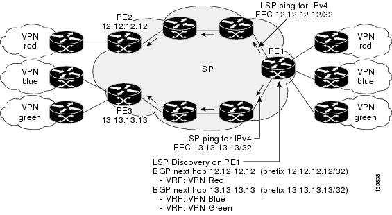
The figure below shows how the BGP next hop neighbor discovery process works for a simple VPN scenario for an Internet service provider (ISP). In this example, there are three VPNs associated with device PE1: red, blue, and green. From the perspective of device PE1, these VPNs are reachable remotely through BGP next hop neighbors PE2 (device ID: 12.12.12.12) and PE3 (device ID: 13.13.13.13). When the BGP next hop neighbor discovery process is enabled on device PE1, a database is generated based on the local VRF and global routing tables. The database in this example contains two BGP next hop device entries: PE2 12.12.12.12 and PE3 13.13.13.13. The routing entries are maintained per next hop device to distinguish which next hop devices belong within which particular VRF. For each next hop device entry, the IPv4 Forward Equivalence Class (FEC) of the BGP next hop device in the global routing table is provided so that it can be used by the MPLS LSP ping operation.
LSP Discovery
The LSP discovery option of an LSP Health Monitor operation provides the capability to discover the equal-cost multipaths for carrying MPLS traffic between the source and destination PE devices. Network connectivity measurements can then be performed for each of the paths that were discovered.
The general process for LSP discovery is as follows:
- BGP next hop neighbors are discovered using the BGP next hop neighbor discovery process. For more information about the BGP next hop neighbor discovery process, see the "Discovery of Neighboring PE Routers" section.
Once the LSP Health Monitor operation is started, a single IP SLAs operation is automatically created for each applicable PE (BGP next hop) neighbor. Only a single path to each applicable PE neighbor is discovered during this initial step of the LSP discovery process. For each next hop neighbor, the LSP Health Monitor creates an LSP discovery group (that initially consists of only the one discovered path) and assigns the group with a unique identification number. For more information about LSP discovery groups, see the "LSP Discovery Groups" section.
- An LSP discovery request is sent by the LSP Health Monitor to the LSP discovery subsystem for each applicable BGP next hop neighbor. For each next hop neighbor in which an appropriate response is received, MPLS echo requests are sent one-by-one from the source PE device to discover the equal-cost multipaths. The parameters that uniquely identify each equal-cost multipath (127/8 destination IP address [LSP selector] and the PE outgoing interface) are added to the associated LSP discovery database.
Note
For a given LSP Health Monitor operation, the user can define the maximum number of BGP next hop neighbors that can be concurrently undergoing LSP discovery. - Each individual IP SLAs operation (created for each applicable PE neighbor) uses an IP SLAs LSP ping superoperation to measure network connectivity across all equal-cost multipaths between the source PE device and discovered destination PE device. The IP SLAs superoperation operates by sending an LSP ping packet to the destination PE device and adjusting the LSP ping 127/8 LSP selector IP address for each discovered equal-cost multipath. For example, assume that there are three equal-cost multipaths to a destination PE device and the identified LSP selector IP addresses are 127.0.0.1, 127.0.0.5, and 127.0.0.6. The IP SLAs superoperation would sequentially send three LSP ping packets using the identified LSP selector IP addresses for directing the superoperation across the three paths. This technique ensures that there is only a single IP SLAs LSP ping operation for each source and destination PE device pair, and significantly reduces the number of active LSP ping operations sent by the source PE device.
The figure below illustrates a simple VPN scenario. This network consists of a core MPLS VPN with two PE devices (device PE1 and device PE2) belonging to the VRF named VPN blue. Suppose device PE1 is the source PE device for an LSP Health Monitor operation with the LSP discovery option enabled and that device PE2 is discovered by the BGP discovery process as a BGP next hop neighbor to device PE1. If path 1 and path 2 are equal-cost multipaths between device PE1 to device PE2, then the LSP discovery process would create an LSP discovery group consisting of path 1 and path 2. An IP SLAs LSP ping superoperation would also be created to monitor network availability across each path.

LSP Discovery Groups
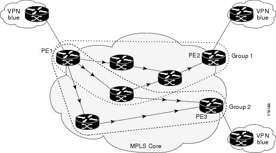
A single LSP Health Monitor operation can be comprised of several LSP discovery groups depending on the number of BGP next hop neighbors discovered by the BGP next hop neighbor discovery process. Each LSP discovery group corresponds to one BGP next hop neighbor and is assigned a unique identification number (starting with the number 1). The figure below illustrates a simple VPN scenario. This network consists of a core MPLS VPN with three PE devices (device PE1, PE2, and PE3) belonging to the VRF named VPN blue. Suppose device PE1 is the source PE device for an LSP Health Monitor operation with the LSP discovery option enabled and that device PE2 and PE3 are discovered by the BGP discovery process as BGP next hop neighbors to device PE1. LSP discovery group 1 is created for the equal-cost multipaths between device PE1 to device PE2 and LSP discovery group 2 is created for the equal-cost multipaths between device PE1 to device PE3.
Once the LSP Health Monitor operation is started, a single IP SLAs operation is automatically created for each applicable PE (BGP next hop) neighbor. Each IP SLAs operation (created for each applicable PE neighbor) uses an IP SLAs LSP ping superoperation to measure network connectivity across all equal-cost multipaths between the source PE device and discovered destination PE device. Each LSP ping superoperation corresponds to a single LSP discovery group.
The LSP ping superoperation operates by sending an LSP ping packet to the destination PE device and adjusting the LSP ping 127/8 LSP selector IP address for each discovered equal-cost multipath. The network connectivity statistics collected by each equal-cost multipath is aggregated and stored in one-hour increments (data can be collected for a maximum of two hours). Results are stored as group averages representative of all the equal-cost multipaths within the LSP discovery group for a given one-hour increment.
Each equal-cost multipath discovered between the source PE device and a BGP next hop neighbor is uniquely identified with the following parameters:
- 127/8 destination IP address (LSP selector) within the local host IP address range
- PE outgoing interface
The database for an LSP discovery group is updated if any of the following events occur:
IP SLAs LSP Ping and LSP Traceroute
The LSP Health Monitor feature introduces support for the IP SLAs LSP ping and IP SLAs LSP traceroute operations. These operations are useful for troubleshooting network connectivity issues and determining network availability in an MPLS VPN. When using the LSP Health Monitor, IP SLAs LSP ping and LSP traceroute operations are automatically created to measure network connectivity between the source PE device and the discovered destination PE devices. Individual IP SLAs LSP ping and LSP traceroute operations can also be manually configured. Manual configuration of these operations can be useful for troubleshooting a connectivity issue.
The IP SLAs LSP ping and IP SLAs LSP traceroute operations are based on the same infrastructure used by the MPLS LSP Ping and MPLS LSP Traceroute features, respectively, for sending and receiving echo reply and request packets to test LSPs.
The LSP discovery does not support IP SLAs traceroute operations.
Proactive Threshold Monitoring for the LSP Health Monitor
Proactive threshold monitoring support for the LSP Health Monitor feature provides the capability for triggering SNMP trap notifications and syslog messages when user-defined reaction conditions (such as a connection loss or timeout) are met. Configuring threshold monitoring for an LSP Health Monitor operation is similar to configuring threshold monitoring for a standard IP SLAs operation.
LSP Discovery Option Enabled
If the LSP discovery option for an LSP Health Monitor operation is enabled, SNMP trap notifications can be generated when one of the following events occurs:
- LSP discovery for a particular BGP next hop neighbor fails.
- Operational status of an LSP discovery group changes.
Possible reasons for which LSP discovery can fail for a particular BGP next hop neighbor are as follows:
- Expiration of time allowed for a BGP next hop neighbor to respond to an LSP discovery request.
- Return code is "Broken" or "Unexplorable" for all paths leading to the BGP next hop neighbor.
The table below describes the conditions for which the operational status of an LSP discovery group can change. Whenever an individual IP SLAs LSP ping operation of an LSP discovery group is executed, a return code is generated. Depending on the value of the return code and the current status of the LSP discovery group, the group status can change.
| Table 1 | Conditions for Which an LSP Discovery Group Status Changes |
|
Individual IP SLAs Operation Return Code |
Current Group Status = UP |
Current Group Status = PARTIAL |
Current Group Status = DOWN |
|---|---|---|---|
|
OK |
No group status change. |
If return codes for all paths in the group are OK, then the group status changes to UP. |
Group status changes to PARTIAL. |
|
Broken or Unexplorable |
Group status changes to PARTIAL. |
If return codes for all paths in the group are Broken or Unexplorable, then the group status changes to DOWN. |
No group status change. |
The return code for an individual IP SLAs LSP ping operation can be one of the following:
- OK--Indicates that the LSP is working properly. The customer VPN traffic will be sent across this path.
- Broken--Indicates that the LSP is broken. Customer VPN traffic will not be sent across this path and may be discarded.
- Unexplorable--Indicates that not all the paths to this PE neighbor have been discovered. This may be due to a disruption along the LSP or because the number of 127/8 IP addresses used for LSP selection has been exhausted.
The status of an LSP discovery group can be one of the following:
- UNKNOWN--Indicates that group status has not yet been determined and that the paths belonging to the group are in the process of being tested for the first time. Once this initial test is complete, the group status will change to UP, PARTIAL, or DOWN.
- UP--Indicates that all the paths within the group are active and no operation failures have been detected.
- PARTIAL--Indicates that an operation failure has been detected for one or more, but not all, of the paths within the group.
- DOWN--Indicates that an operation failure has been detected for all the paths within the group.
Secondary Frequency Option
With the introduction of the LSP Health Monitor feature, a new threshold monitoring parameter has been added that allows you to specify a secondary frequency. If the secondary frequency option is configured and a failure (such as a connection loss or timeout) is detected for a particular path, the frequency at which the path is remeasured will increase to the secondary frequency value (testing at a faster rate). When the configured reaction condition is met (such as N consecutive connection losses or N consecutive timeouts), an SNMP trap and syslog message can be sent and the measurement frequency will return to its original frequency value.
Multioperation Scheduling for an LSP Health Monitor
Multioperation scheduling support for the LSP Health Monitor feature provides the capability to easily schedule the automatically created IP SLAs operations (for a given LSP Health Monitor operation) to begin at intervals equally distributed over a specified duration of time (schedule period) and to restart at a specified frequency. Multioperation scheduling is particularly useful in cases where the LSP Health Monitor is enabled on a source PE device that has a large number of PE neighbors and, therefore, a large number of IP SLAs operations running at the same time.
Newly created IP SLAs operations (for newly discovered BGP next hop neighbors) are added to the same schedule period as the operations that are currently running. To prevent too many operations from starting at the same time, the multioperation scheduling feature will schedule the operations to begin at random intervals uniformly distributed over the schedule period.
Configuring a multioperation schedule for an LSP Health Monitor is similar to configuring a standard multioperation schedule for a group of individual IP SLAs operations.
LSP Discovery Enabled
When a multioperation schedule for an LSP Health Monitor operation with LSP discovery is started, the BGP next hop neighbors are discovered, and network connectivity to each applicable neighbor is monitored using only a single LSP. Initially, network connectivity between the source PE device and discovered destination PE device is measured across only a single path. This initial condition is the same as if an LSP Health Monitor operation was performed without LSP discovery.
Specific information about the IP SLAs LSP ping operations that are created for newly discovered equal-cost paths during the succeeding iterations of the LSP discovery process are stored in the LSP discovery group database. These newly created IP SLAs LSP ping operations will start collecting data at the next iteration of network connectivity measurements for their associated LSP discovery group.
The start times for the individual IP SLAs LSP ping operations for each LSP discovery group is based on the number of LSP discovery groups and the schedule period of the multioperation schedule. For example, if three LSP discovery groups (Group 1, Group 2, and Group 3) are scheduled to run over a period of 60 seconds, the first LSP ping operation of Group 1 will start at 0 seconds, the first LSP ping operation of Group 2 will start at 20 seconds, and the first LSP ping operation of Group 3 will start at 40 seconds. The remaining individual IP SLAs LSP ping operations for each LSP discovery group will run sequentially after completion of the first LSP ping operation. For each LSP discovery group, only one LSP ping operation runs at a time.
How to Configure LSP Health Monitor Operations
- Configuring an LSP Health Monitor Operation
- Scheduling LSP Health Monitor Operations
- Manually Configuring and Scheduling an IP SLAs LSP Ping or LSP Traceroute Operation
- Verifying and Troubleshooting LSP Health Monitor Operations
Configuring an LSP Health Monitor Operation
Perform only one of the following tasks:
- Configuring an LSP Health Monitor Operation without LSP Discovery on a PE Device
- Configuring the LSP Health Monitor Operation with LSP Discovery on a PE Device
Configuring an LSP Health Monitor Operation without LSP Discovery on a PE Device
Note | If LSP discovery is disabled, only a single path between the source PE device and each BGP next hop neighbor is discovered. |
DETAILED STEPS
Configuring the LSP Health Monitor Operation with LSP Discovery on a PE Device
Note |
|
DETAILED STEPS
| Command or Action | Purpose | |||
|---|---|---|---|---|
Step 1 |
enable
Example: Device> enable |
Enables privileged EXEC mode. | ||
Step 2 |
configure
terminal
Example: Device# configure terminal |
Enters global configuration mode. | ||
Step 3 |
mpls
discovery
vpn
next-hop
Example: Device(config)# mpls discovery vpn next-hop |
(Optional) Enables the MPLS VPN BGP next hop neighbor discovery process.
| ||
Step 4 |
mpls
discovery
vpn
interval
seconds
Example: Device(config)# mpls discovery vpn interval 120 |
(Optional) Specifies the time interval at which routing entries that are no longer valid are removed from the BGP next hop neighbor discovery database of an MPLS VPN. | ||
Step 5 |
auto
ip
sla
mpls-lsp-monitor
operation-number
Example: Device(config)# auto ip sla mpls-lsp-monitor 1 |
Begins configuration for an LSP Health Monitor operation and enters auto IP SLAs MPLS configuration mode.
| ||
Step 6 |
type
echo
[ipsla-vrf-all |
vrf
vpn-name]
Example: Device(config-auto-ip-sla-mpls)# type echo ipsla-vrf-all |
Enters MPLS parameters configuration mode and allows the user to configure the parameters for an IP SLAs LSP ping operation using the LSP Health Monitor. | ||
Step 7 | Configure optional parameters for the IP SLAs LSP echo operation.
|
(Optional) See Steps 7 through 21 in the "Configuring an LSP Health Monitor Operation Without LSP Discovery on a PE Device" section. | ||
Step 8 |
path-discover
Example: Device(config-auto-ip-sla-mpls-params)# path-discover |
Enables the LSP discovery option for an IP SLAs LSP Health Monitor operation and enters LSP discovery parameters configuration submode. | ||
Step 9 |
hours-of-statistics-kept
hours
Example: Device(config-auto-ip-sla-mpls-lpd-params)# hours-of-statistics-kept 1 |
(Optional) Sets the number of hours for which LSP discovery group statistics are maintained for an LSP Health Monitor operation. | ||
Step 10 |
force-explicit-null
Example: Device(config-auto-ip-sla-mpls-lpd-params)# force-explicit-null |
(Optional) Adds an explicit null label to all echo request packets of an LSP Health Monitor operation. | ||
Step 11 |
interval
milliseconds
Example: Device(config-auto-ip-sla-mpls-lpd-params)# interval 2 |
(Optional) Specifies the time interval between MPLS echo requests that are sent as part of the LSP discovery process for an LSP Health Monitor operation. | ||
Step 12 |
lsp-selector-base
ip-address
Example: Device(config-auto-ip-sla-mpls-lpd-params)# lsp-selector-base 127.0.0.2 |
(Optional) Specifies the base IP address used to select the LSPs belonging to the LSP discovery groups of an LSP Health Monitor operation. | ||
Step 13 |
maximum-sessions
number
Example: Device(config-auto-ip-sla-mpls-lpd-params)# maximum-sessions 2 |
(Optional) Specifies the maximum number of BGP next hop neighbors that can be concurrently undergoing LSP discovery for a single LSP Health Monitor operation.
| ||
Step 14 |
scan-period
minutes
Example: Device(config-auto-ip-sla-mpls-lpd-params)# scan-period 30 |
(Optional) Sets the amount of time after which the LSP discovery process can restart for an LSP Health Monitor operation. | ||
Step 15 |
session-timeout
seconds
Example: Device(config-auto-ip-sla-mpls-lpd-params)# session-timeout 60 |
(Optional) Sets the amount of time the LSP discovery process for an LSP Health Monitor operation waits for a response to its LSP discovery request for a particular BGP next hop neighbor. | ||
Step 16 |
timeout
seconds
Example: Device(config-auto-ip-sla-mpls-lpd-params)# timeout 4 |
(Optional) Sets the amount of time the LSP discovery process for an LSP Health Monitor operation waits for a response to its echo request packets.
| ||
Step 17 |
exit
Example: Device(config-auto-ip-sla-mpls-lpd-params)# exit |
Exits LSP discovery parameters configuration submode and returns to MPLS parameters configuration mode. | ||
Step 18 |
exit
Example: Device(config-auto-ip-sla-mpls-params)# exit |
Exits MPLS parameters configuration mode and returns to global configuration mode. | ||
Step 19 |
auto
ip
sla
mpls-lsp-monitor
reaction-configuration
operation-number
react
lpd
{lpd-group [retry
number] |
tree-trace} [action-type
trapOnly]
Example: Device(config)# auto ip sla mpls-lsp-monitor reaction-configuration 1 react lpd lpd-group retry 3 action-type trapOnly |
(Optional) Configures the proactive threshold monitoring parameters for an LSP Health Monitor operation with LSP discovery enabled. | ||
Step 20 |
ip
sla
logging
traps
Example: Device(config)# ip sla logging traps |
(Optional) Enables the generation of SNMP system logging messages specific to IP SLAs trap notifications. | ||
Step 21 |
exit
Example: Device(config)# exit |
Exits global configuration mode and returns to privileged EXEC mode. |
Scheduling LSP Health Monitor Operations
Note |
|
DETAILED STEPS
| Command or Action | Purpose | |
|---|---|---|
Step 1 |
enable
Example: Device> enable |
Enables privileged EXEC mode. |
Step 2 |
configure
terminal
Example: Device# configure terminal |
Enters global configuration mode. |
Step 3 |
auto
ip
sla
mpls-lsp-monitor
schedule
operation-number
schedule-period
seconds
[frequency [seconds]] [start-time {after
hh
:
mm
:
ss |
hh
:
mm[:
ss] [month
day |
day
month] |
now |
pending}]
Example: Device(config)# auto ip sla mpls-lsp-monitor schedule 1 schedule-period 60 start-time now |
Configures the scheduling parameters for an LSP Health Monitor operation. |
Step 4 |
exit
Example: Device(config)# exit |
Exits to privileged EXEC mode. |
Step 5 |
show
ip
sla
configuration
Example: Device# show ip sla configuration |
(Optional) Displays the IP SLAs configuration details. |
Troubleshooting Tips
Use the debug ip sla trace and debug ip sla error commands to help troubleshoot issues with an individual IP SLAs LSP ping or LSP traceroute operation. Use the debug ip sla mpls-lsp-monitor command to help troubleshoot issues with an IP SLAs LSP Health Monitor operation.
What to Do Next
To display the results of an individual IP SLAs operation use the show ip sla statistics and show ip sla statistics aggregated commands. Checking the output for fields that correspond to criteria in your service level agreement will help you determine whether the service metrics are acceptable.
Manually Configuring and Scheduling an IP SLAs LSP Ping or LSP Traceroute Operation
- mpls lsp ping ipv4 destination-address destination-mask [force-explicit-null] [lsp-selector ip-address] [src-ip-addr source-address] [reply {dscp dscp-value | mode {ipv4 | router-alert}}]
- mpls lsp trace ipv4 destination-address destination-mask [force-explicit-null] [lsp-selector ip-address] [src-ip-addr source-address] [reply {dscp dscp-value | mode {ipv4 | router-alert}}]
DETAILED STEPS
| Command or Action | Purpose | |||
|---|---|---|---|---|
Step 1 |
enable
Example: Device> enable |
Enables privileged EXEC mode. | ||
Step 2 |
configure
terminal
Example: Device# configure terminal |
Enters global configuration mode. | ||
Step 3 |
ip
sla
operation-number
Example: Device(config)# ip sla 1 |
Begins configuration for an IP SLAs operation and enters IP SLA configuration mode. | ||
Step 4 | Do one of the following:
Example: Device(config-ip-sla)# mpls lsp ping ipv4 192.168.1.4 255.255.255.255 lsp-selector 127.1.1.1 Example: Device(config-ip-sla)# mpls lsp trace ipv4 192.168.1.4 255.255.255.255 lsp-selector 127.1.1.1 | |||
Step 5 |
exp
exp-bits
Example: Device(config-sla-monitor-lspPing)# exp 5 |
(Optional) Specifies the experimental field value in the header for an echo request packet of an IP SLAs operation.
| ||
Step 6 |
request-data-size
bytes
Example: Device(config-sla-monitor-lspPing)# request-data-size 200 |
(Optional) Specifies the protocol data size for a request packet of an IP SLAs operation. | ||
Step 7 |
secondary-frequency
{connection-loss |
timeout}
frequency
Example: Device(config-sla-monitor-lspPing)# secondary-frequency connection-loss 10 |
(Optional) Sets the faster measurement frequency (secondary frequency) to which an IP SLAs operation should change when a reaction condition occurs. | ||
Step 8 |
tag
text
Example: Device(config-sla-monitor-lspPing)# tag testgroup |
(Optional) Creates a user-specified identifier for an IP SLAs operation. | ||
Step 9 |
threshold
milliseconds
Example: Device(config-sla-monitor-lspPing)# threshold 6000 |
(Optional) Sets the upper threshold value for calculating network monitoring statistics created by an IP SLAs operation. | ||
Step 10 |
timeout
milliseconds
Example: Device(config-sla-monitor-lspPing)# timeout 7000 |
(Optional) Specifies the amount of time the IP SLAs operation waits for a response from its request packet. | ||
Step 11 |
ttl
time-to-live
Example: Device(config-sla-monitor-lspPing)# ttl 200 |
(Optional) Specifies the maximum hop count for an echo request packet of an IP SLAs operation. | ||
Step 12 |
exit
Example: Device(config-sla-monitor-lspPing)# exit |
Exits LSP ping or LSP trace configuration submode and returns to global configuration mode. | ||
Step 13 |
ip
sla
reaction-configuration
operation-number
[react
monitored-element] [threshold-type {never |
immediate |
consecutive [consecutive-occurrences] |
xofy [x-value
y-value] |
average [number-of-probes]}] [threshold-value
upper-threshold
lower-threshold] [action-type {none |
trapOnly |
triggerOnly |
trapAndTrigger}]
Example: Device(config)# ip sla reaction-configuration 1 react connectionLoss threshold-type consecutive 3 action-type traponly |
(Optional) Configures certain actions to occur based on events under the control of IP SLAs. | ||
Step 14 |
ip
sla
logging
traps
Example: Device(config)# ip sla logging traps |
(Optional) Enables the generation of SNMP system logging messages specific to IP SLAs trap notifications. | ||
Step 15 |
ip
sla
schedule
operation-number
[life {forever |
seconds}] [start-time {hh
:
mm[:
ss] [month
day |
day
month] |
pending |
now |
after
hh
:
mm
:
ss}] [ageout
seconds] [recurring]
Example: Device(config)# ip sla schedule 1 start-time now |
Configures the scheduling parameters for an IP SLAs operation. | ||
Step 16 |
exit
Example: Device(config)# exit |
Exits global configuration submode and returns to privileged EXEC mode. |
Troubleshooting Tips
Use the debug ip sla trace and debug ip sla error commands to help troubleshoot issues with an individual IP SLAs LSP ping or LSP traceroute operation.
What to Do Next
To display the results of an individual IP SLAs operation use the show ip sla statistics and show ip sla statistics aggregated commands. Checking the output for fields that correspond to criteria in your service level agreement will help you determine whether the service metrics are acceptable.
Verifying and Troubleshooting LSP Health Monitor Operations
DETAILED STEPS
| Command or Action | Purpose | |||
|---|---|---|---|---|
Step 1 |
debug
ip
sla
error
[operation-number]
Example: Device# debug ip sla error |
(Optional) Enables debugging output of IP SLAs operation run-time errors. | ||
Step 2 |
debug
ip
sla
mpls-lsp-monitor
[operation-number]
Example: Device# debug ip sla mpls-lsp-monitor |
(Optional) Enables debugging output of LSP Health Monitor operations. | ||
Step 3 |
debug
ip
sla
trace
[operation-number]
Example: Device# debug ip sla trace |
(Optional) Enables debugging output for tracing the execution of IP SLAs operations. | ||
Step 4 |
show
ip
sla
mpls-lsp-monitor
collection-statistics
[group-id]
Example: Device# show ip sla mpls-lsp-monitor collection-statistics 100001 |
(Optional) Displays the statistics for IP SLAs operations belonging to an LSP discovery group of an LSP Health Monitor operation.
| ||
Step 5 |
show
ip
sla
mpls-lsp-monitor
configuration
[operation-number]
Example: Device# show ip sla mpls-lsp-monitor configuration 1 |
(Optional) Displays configuration settings for LSP Health Monitor operations. | ||
Step 6 |
show
ip
sla
mpls-lsp-monitor
lpd
operational-state
[group-id]
Example: Device# show ip sla mpls-lsp-monitor lpd operational-state 100001 |
(Optional) Displays the operational status of the LSP discovery groups belonging to an LSP Health Monitor operation.
| ||
Step 7 |
show
ip
sla
mpls-lsp-monitor
neighbors
Example: Device# show ip sla mpls-lsp-monitor neighbors |
(Optional) Displays routing and connectivity information about MPLS VPN BGP next hop neighbors discovered by the LSP Health Monitor operation. | ||
Step 8 |
show
ip
sla
mpls-lsp-monitor
scan-queue
operation-number
Example: Device# show ip sla mpls-lsp-monitor scan-queue 1 |
(Optional) Displays information about adding or deleting BGP next hop neighbors from a particular MPLS VPN of an LSP Health Monitor operation. | ||
Step 9 |
show
ip
sla
mpls-lsp-monitor
summary
[operation-number [group [group-id]]]
Example: Device# show ip sla mpls-lsp-monitor summary |
(Optional) Displays BGP next hop neighbor and LSP discovery group information for LSP Health Monitor operations.
| ||
Step 10 |
show
ip
sla
statistics
[operation-number] [details]
Example: Device# show ip sla statistics 100001 |
(Optional) Displays the current operational status and statistics of all IP SLAs operations or a specified operation.
| ||
Step 11 |
show
ip
sla
statistics
aggregated
[operation-number] [details]
Example: Device# show ip sla statistics aggregated 100001 |
(Optional) Displays the aggregated statistical errors and distribution information for all IP SLAs operations or a specified operation.
| ||
Step 12 |
show
mpls
discovery
vpn
Example: Device# show mpls discovery vpn |
(Optional) Displays routing information relating to the MPLS VPN BGP next hop neighbor discovery process. |
Configuration Examples for LSP Health Monitors
- Example Configuring and Verifying the LSP Health Monitor Without LSP Discovery
- Example Configuring and Verifying the LSP Health Monitor with LSP Discovery
- Example Manually Configuring an IP SLAs LSP Ping Operation
Example Configuring and Verifying the LSP Health Monitor Without LSP Discovery
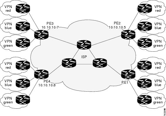
The figure below illustrates a simple VPN scenario for an ISP. This network consists of a core MPLS VPN with four PE devices belonging to three VPNs: red, blue, and green. From the perspective of device PE1, these VPNs are reachable remotely through BGP next hop devices PE2 (device ID: 10.10.10.5), PE3 (device ID: 10.10.10.7), and PE4 (device ID: 10.10.10.8).
The following example shows how to configure operation parameters, proactive threshold monitoring, and scheduling options on PE1 (see the figure above) using the LSP Health Monitor. In this example, the LSP discovery option is enabled for LSP Health Monitor operation 1. Operation 1 is configured to automatically create IP SLAs LSP ping operations for all BGP next hop neighbors (PE2, PE3, and PE4) in use by all VRFs (red, blue, and green) associated with device PE1. The BGP next hop neighbor process is enabled, and the time interval at which routing entries that are no longer valid are removed from the BGP next hop neighbor discovery database is set to 60 seconds. The time interval at which the LSP Health Monitor checks the scan queue for BGP next hop neighbor updates is set to 1 minute. The secondary frequency option is enabled for both connection loss and timeout events, and the secondary frequency is set to 10 seconds. As specified by the proactive threshold monitoring configuration, when three consecutive connection loss or timeout events occur, an SNMP trap notification is sent. Multioperation scheduling and the generation of IP SLAs SNMP system logging messages are enabled.
PE1 Configuration
mpls discovery vpn interval 60
mpls discovery vpn next-hop
!
auto ip sla mpls-lsp-monitor 1
 type echo ipsla-vrf-all
 timeout 1000
 scan-interval 1
 secondary-frequency both 10
!
auto ip sla mpls-lsp-monitor reaction-configuration 1 react connectionLoss threshold-type consecutive 3 action-type trapOnly
auto ip sla mpls-lsp-monitor reaction-configuration 1 react timeout threshold-type consecutive 3 action-type trapOnly
ip sla traps
snmp-server enable traps rtr
!
auto ip sla mpls-lsp-monitor schedule 1 schedule-period 60 start-time now
The following is sample output from the show ip sla mpls-lsp-monitor configuration command for PE1:
PE1# show ip sla mpls-lsp-monitor configuration 1
Entry Number : 1
Modification time   : *12:18:21.830 PDT Fri Aug 19 2005
Operation Type      : echo
Vrf Name            : ipsla-vrf-all
Tag                 :
EXP Value           : 0
Timeout(ms)         : 1000
Threshold(ms)       : 5000
Frequency(sec)      : Equals schedule period
LSP Selector        : 127.0.0.1
ScanInterval(min)   : 1
Delete Scan Factor  : 1
Operations List     : 100001-100003
Schedule Period(sec): 60
Request size        : 100
Start Time          : Start Time already passed
SNMP RowStatus      : Active
TTL value           : 255
Reply Mode          : ipv4
Reply Dscp Bits     :
Secondary Frequency : Enabled on Timeout
         Value(sec) : 10
Reaction Configs    :
    Reaction        : connectionLoss
    Threshold Type  : Consecutive
    Threshold Count : 3
    Action Type     : Trap Only
    Reaction        : timeout
    Threshold Type  : Consecutive
    Threshold Count : 3
    Action Type     : Trap Only
The following is sample output from the show mpls discovery vpn command for PE1:
PE1# show mpls discovery vpn
Refresh interval set to 60 seconds.
Next refresh in 46 seconds
Next hop 10.10.10.5 (Prefix: 10.10.10.5/32)
        in use by: red, blue, green
Next hop 10.10.10.7 (Prefix: 10.10.10.7/32)
        in use by: red, blue, green
Next hop 10.10.10.8 (Prefix: 10.10.10.8/32)
        in use by: red, blue, green
The following is sample output from the show ip sla mpls-lsp-monitor neighbors command for PE1:
PE1# show ip sla mpls-lsp-monitor neighbors
IP SLA MPLS LSP Monitor Database : 1
BGP Next hop 10.10.10.5 (Prefix: 10.10.10.5/32)  OK
  ProbeID: 100001 (red, blue, green)
BGP Next hop 10.10.10.7 (Prefix: 10.10.10.7/32)  OK
  ProbeID: 100002 (red, blue, green)
BGP Next hop 10.10.10.8 (Prefix: 10.10.10.8/32)  OK
  ProbeID: 100003 (red, blue, green)
The following is sample output from the show ip sla mpls-lsp-monitor scan-queue 1 and debug ip sla mpls-lsp-monitor commands when IP connectivity from PE1 to PE4 is lost. This output shows that connection loss to each of the VPNs associated with PE4 (red, blue, and green) was detected and that this information was added to the LSP Health Monitor scan queue. Also, since PE4 is no longer a valid BGP next hop neighbor, the IP SLAs operation for PE4 (Probe 10003) is being deleted.
PE1# show ip sla mpls-lsp-monitor scan-queue 1
Next scan Time after: 20 Secs
Next Delete scan Time after: 20 Secs
BGP Next hop    Prefix             vrf                              Add/Delete?
10.10.10.8      0.0.0.0/0          red                              Del(100003)
10.10.10.8      0.0.0.0/0          blue                             Del(100003)
10.10.10.8      0.0.0.0/0          green                            Del(100003)
PE1# debug ip sla mpls-lsp-monitor
IP SLAs MPLSLM debugging for all entries is on
*Aug 19 19:48: IP SLAs MPLSLM(1):Next hop 10.10.10.8 added in DeleteQ(1)
*Aug 19 19:49: IP SLAs MPLSLM(1):Removing vrf red from tree entry 10.10.10.8
*Aug 19 19:56: IP SLAs MPLSLM(1):Next hop 10.10.10.8 added in DeleteQ(1)
*Aug 19 19:56: IP SLAs MPLSLM(1):Next hop 10.10.10.8 added in DeleteQ(1)
*Aug 19 19:49: IP SLAs MPLSLM(1):Removing vrf blue from tree entry 10.10.10.8
*Aug 19 19:49: IP SLAs MPLSLM(1):Removing vrf green from tree entry 10.10.10.8
*Aug 19 19:49: IP SLAs MPLSLM(1):Removing Probe 100003
The following is sample output from the show ip sla mpls-lsp-monitor scan-queue 1 and debug ip sla mpls-lsp-monitor commands when IP connectivity from PE1 to PE4 is restored. This output shows that each of the VPNs associated with PE4 (red, blue, and green) were discovered and that this information was added to the LSP Health Monitor scan queue. Also, since PE4 is a newly discovered BGP next hop neighbor, a new IP SLAs operation for PE4 (Probe 100005) is being created and added to the LSP Health Monitor multioperation schedule. Even though PE4 belongs to three VPNs, only one IP SLAs operation is being created.
PE1# show ip sla mpls-lsp-monitor scan-queue 1
Next scan Time after: 23 Secs
Next Delete scan Time after: 23 Secs
BGP Next hop    Prefix             vrf                              Add/Delete?
10.10.10.8      10.10.10.8/32      red                              Add
10.10.10.8      10.10.10.8/32      blue                             Add
10.10.10.8      10.10.10.8/32      green                            Add
PE1# debug ip sla mpls-lsp-monitor
IP SLAs MPLSLM debugging for all entries is on
*Aug 19 19:59: IP SLAs MPLSLM(1):Next hop 10.10.10.8 added in AddQ
*Aug 19 19:59: IP SLAs MPLSLM(1):Next hop 10.10.10.8 added in AddQ
*Aug 19 19:59: IP SLAs MPLSLM(1):Next hop 10.10.10.8 added in AddQ
*Aug 19 19:59: IP SLAs MPLSLM(1):Adding vrf red into tree entry 10.10.10.8
*Aug 19 19:59: IP SLAs MPLSLM(1):Adding Probe 100005
*Aug 19 19:59: IP SLAs MPLSLM(1):Adding ProbeID 100005 to tree entry 10.10.10.8 (1)
*Aug 19 19:59: IP SLAs MPLSLM(1):Adding vrf blue into tree entry 10.10.10.8
*Aug 19 19:59: IP SLAs MPLSLM(1):Duplicate in AddQ 10.10.10.8
*Aug 19 19:59: IP SLAs MPLSLM(1):Adding vrf green into tree entry 10.10.10.8
*Aug 19 19:59: IP SLAs MPLSLM(1):Duplicate in AddQ 10.10.10.8
*Aug 19 19:59: IP SLAs MPLSLM(1):Added Probe(s) 100005 will be scheduled after 26 secs over schedule period 60
Example Configuring and Verifying the LSP Health Monitor with LSP Discovery
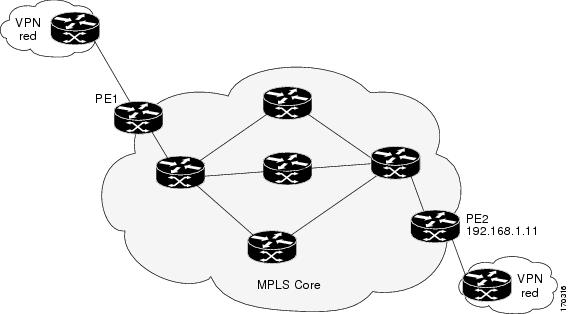
The figure below illustrates a simple VPN scenario for an ISP. This network consists of a core MPLS VPN with two PE devices belonging to a VPN named red. From the perspective of device PE1, there are three equal-cost multipaths available to reach device PE2.
The following example shows how to configure operation parameters, proactive threshold monitoring, and scheduling options on PE1 (see the figure above) using the LSP Health Monitor. In this example, the LSP discovery option is enabled for LSP Health Monitor operation 100. Operation 100 is configured to automatically create IP SLAs LSP ping operations for all equal-cost multipaths between PE1 and PE2. The BGP next hop neighbor process is enabled, and the time interval at which routing entries that are no longer valid are removed from the BGP next hop neighbor discovery database is set to 30 seconds. The time interval at which the LSP Health Monitor checks the scan queue for BGP next hop neighbor updates is set to 1 minute. The secondary frequency option is enabled for both connection loss and timeout events, and the secondary frequency is set to 5 seconds. The explicit null label option for echo request packets is enabled. The LSP rediscovery time period is set to 3 minutes. As specified by the proactive threshold monitoring configuration, an SNMP trap notification will be sent when an LSP discovery group status changes occurs. Multioperation scheduling and the generation of IP SLAs SNMP system logging messages are enabled.
PE1 Configuration
mpls discovery vpn next-hop
mpls discovery vpn interval 30
!
auto ip sla mpls-lsp-monitor 100
 type echo ipsla-vrf-all
 scan-interval 1
 secondary-frequency both 5
!
 path-discover
 force-explicit-null
 scan-period 3
!
auto ip sla mpls-lsp-monitor reaction-configuration 100 react lpd-group retry 3 action-type trapOnly
!
auto ip sla mpls-lsp-monitor schedule 100 schedule-period 30 start-time now
!
ip sla logging traps
snmp-server enable traps rtr
The following is sample output from the show ip sla mpls-lsp-monitor configuration command for PE1:
PE1# show ip sla mpls-lsp-monitor configuration
Entry Number : 100
Modification time   : *21:50:16.411 GMT Tue Jun 20 2006
Operation Type      : echo
Vrf Name            : ipsla-vrf-all
Tag                 :
EXP Value           : 0
Timeout(ms)         : 5000
Threshold(ms)       : 50
Frequency(sec)      : Equals schedule period
ScanInterval(min)   : 1
Delete Scan Factor  : 1
Operations List     : 100002
Schedule Period(sec): 30
Request size        : 100
Start Time          : Start Time already passed
SNMP RowStatus      : Active
TTL value           : 255
Reply Mode          : ipv4
Reply Dscp Bits     :
Path Discover       : Enable
    Maximum sessions          : 1
    Session Timeout(seconds)  : 120
    Base LSP Selector         : 127.0.0.0
    Echo Timeout(seconds)     : 5
    Send Interval(msec)       : 0
    Label Shimming Mode       : force-explicit-null
    Number of Stats Hours     : 2
    Scan Period(minutes)      : 3
Secondary Frequency : Enabled on Connection Loss and Timeout
         Value(sec) : 5
Reaction Configs    :
    Reaction        : Lpd Group
    Retry Number    : 3
    Action Type     : Trap Only
The following is sample output from the show mpls discovery vpn command for PE1:
PE1# show mpls discovery vpn
Refresh interval set to 30 seconds.
Next refresh in 4 seconds
Next hop 192.168.1.11 (Prefix: 192.168.1.11/32)
        in use by: red
The following is sample output from the show ip sla mpls-lsp-monitor neighbors command for PE1:
PE1# show ip sla mpls-lsp-monitor neighbors
IP SLA MPLS LSP Monitor Database : 100
BGP Next hop 192.168.1.11 (Prefix: 192.168.1.11/32)  OK Paths: 3
  ProbeID: 100001 (red)
The following is sample output from the show ip sla mpls-lsp-monitor lpd operational-state command for LSP discovery group 100001:
PE1# show ip sla mpls-lsp-monitor lpd operational-state
Entry number: 100001
MPLSLM Entry Number: 100
Target FEC Type: LDP IPv4 prefix
Target Address: 192.168.1.11
Number of Statistic Hours Kept: 2
Last time LPD Stats were reset: *21:21:18.239 GMT Tue Jun 20 2006
Traps Type: 3
Latest Path Discovery Mode: rediscovery complete
Latest Path Discovery Start Time: *21:59:04.475 GMT Tue Jun 20 2006
Latest Path Discovery Return Code: OK
Latest Path Discovery Completion Time(ms): 3092
Number of Paths Discovered: 3
Path Information :
Path   Outgoing   Lsp             Link  Conn  Adj             Downstream
Index  Interface  Selector        Type  Id    Addr            Label Stack     Status
1      Et0/0      127.0.0.8       90    0     10.10.18.30     21              OK
2      Et0/0      127.0.0.2       90    0     10.10.18.30     21              OK
3      Et0/0      127.0.0.1       90    0     10.10.18.30     21              OK
The following is sample output from the show ip sla mpls-lsp-monitor collection-statistics command for LSP discovery group 100001:
PE1# show ip sla mpls-lsp-monitor collection-statistics
Entry number: 100001
Start Time Index: *21:52:59.795 GMT Tue Jun 20 2006
Path Discovery Start Time: *22:08:04.507 GMT Tue Jun 20 2006
Target Destination IP address: 192.168.1.11
Path Discovery Status: OK
Path Discovery Completion Time: 3052
Path Discovery Minimum Paths: 3
Path Discovery Maximum Paths: 3
LSP Group Index: 100002
LSP Group Status: up
Total Pass: 36
Total Timeout: 0        Total Fail: 0
Latest Probe Status: 'up,up,up'
Latest Path Identifier: '127.0.0.8-Et0/0-21,127.0.0.2-Et0/0-21,127.0.0.1-Et0/0-21'
Minimum RTT: 280        Maximum RTT: 324        Average RTT: 290
The following is sample output from the show ip sla mpls-lsp-monitor summary command for LSP Health Monitor operation 100:
PE1# show ip sla mpls-lsp-monitor summary 100
Index                    -  MPLS LSP Monitor probe index
Destination              -  Target IP address of the BGP next hop
Status                   -  LPD group status
LPD Group ID             -  Unique index to identify the LPD group
Last Operation Time      -  Last time an operation was attempted by
                            a particular probe in the LPD Group
Index  Destination     Status     LPD Group ID    Last Operation Time
100    192.168.1.11    up         100001          *22:20:29.471 GMT Tue Jun 20 2006
The following is sample output from the show ip sla mpls-lsp-monitor summary command for LSP discovery group 100001:
PE1#show ip sla mpls-lsp-monitor summary 100 group 100001
Group ID                 -  unique number to identify a LPD group
Lsp-selector             -  Unique 127/8 address used to identify a LPD
Last Operation status    -  Latest probe status
Last RTT                 -  Latest Round Trip Time
Last Operation Time      -  Time when the last operation was attempted
Group ID  Lsp-Selector    Status     Failures    Successes   RTT   Last Operation Time
100001    127.0.0.8       up         0           55          320   *22:20:29.471 GMT Tue Jun 20 2006
100001    127.0.0.2       up         0           55          376   *22:20:29.851 GMT Tue Jun 20 2006
100001    127.0.0.1       up         0           55          300   *22:20:30.531 GMT Tue Jun 20 2006
Example Manually Configuring an IP SLAs LSP Ping Operation
The following example shows how to manually configure and schedule an IP SLAs LSP ping operation:
ip sla 1
mpls lsp ping ipv4 192.168.1.4 255.255.255.255 lsp-selector 127.1.1.1
frequency 120
secondary-frequency timeout 30
!
ip sla reaction-configuration 1 react connectionLoss threshold-type consecutive 3 action-type trapOnly
ip sla reaction-configuration 1 react timeout threshold-type consecutive 3 action-type trapOnly
ip sla logging traps
!
ip sla schedule 1 start-time now life forever
Additional References
Related Documents
|
Related Topic |
Document Title |
|---|---|
|
MPLS LSP discovery management tool |
"MPLS EM-MPLS LSP Multipath Tree Trace" chapter of the Multiprotocol Label Switching Configuration Guide |
|
Configuring standard IP access lists |
"Access Control Lists" chapter of the Security Configuration Guide: Securing the Data Plane guide |
|
Multioperation scheduling for IP SLAs |
"Configuring Multioperation Scheduling of IP SLAs Operations" chapter of the Cisco IOS P SLAs Configuration Guide |
|
Proactive threshold monitoring for IP SLAs |
" Configuring Proactive Threshold Monitoring of IP SLAs Operations" chapter of the Cisco IOS IP SLAs Configuration Guide |
|
Cisco IOS commands |
|
|
Cisco IOS IP SLAs commands |
MIBs
Technical Assistance
|
Description |
Link |
|---|---|
|
The Cisco Support and Documentation website provides online resources to download documentation, software, and tools. Use these resources to install and configure the software and to troubleshoot and resolve technical issues with Cisco products and technologies. Access to most tools on the Cisco Support and Documentation website requires a Cisco.com user ID and password. |
Feature Information for LSP Health Monitor Operations
The following table provides release information about the feature or features described in this module. This table lists only the software release that introduced support for a given feature in a given software release train. Unless noted otherwise, subsequent releases of that software release train also support that feature.
Use Cisco Feature Navigator to find information about platform support and Cisco software image support. To access Cisco Feature Navigator, go to www.cisco.com/go/cfn. An account on Cisco.com is not required.
| Table 2 | Feature Information for the LSP Health Monitor |
|
Feature Name |
Releases |
Feature Information |
|---|---|---|
|
IP SLAs--LSP Health Monitor |
12.2(27)SBC 12.2(28)SB 12.2(33)SRA 12.4(6)T Cisco IOS XE Release 2.2 15.0(1)SY 15.0(1)S Cisco IOS XE 3.1.0SG 12.2(50)SY |
The IP SLAs LSP Health Monitor feature provides the capability to proactively monitor Layer 3 MPLS VPNs. |
|
-- |
12.2(31)SB2 12.2(33)SB 12.2(33)SRB 12.2(33)SXH |
For software releases in which this feature was already introduced, new command-line interface (CLI) was implemented that replaces the CLI introduced in the earlier releases |
|
IP SLAs--LSP Health Monitor with LSP Discovery |
12.2(31)SB2 12.2(33)SRB Cisco IOS XE Release 2.2 15.0(1)S Cisco IOS XE 3.1.0SG 12.2(50)SY |
The LSP discovery capability was added. |
Cisco and the Cisco logo are trademarks or registered trademarks of Cisco and/or its affiliates in the U.S. and other countries. To view a list of Cisco trademarks, go to this URL: www.cisco.com/go/trademarks. Third-party trademarks mentioned are the property of their respective owners. The use of the word partner does not imply a partnership relationship between Cisco and any other company. (1110R)
Any Internet Protocol (IP) addresses and phone numbers used in this document are not intended to be actual addresses and phone numbers. Any examples, command display output, network topology diagrams, and other figures included in the document are shown for illustrative purposes only. Any use of actual IP addresses or phone numbers in illustrative content is unintentional and coincidental.