
 Feedback
Contents
- Configuring EIGRP
- Finding Feature Information
- Information About Configuring EIGRP
- EIGRP Features
- EIGRP Autonomous System Configuration
- EIGRP Named Configuration
- EIGRP IPv6 VRF-Lite
- EIGRP vNETs
- EIGRP vNET Interface and Command Inheritance
- EIGRP Neighbor Relationship Maintenance
- Neighbor Authentication
- DUAL Finite State Machine
- Protocol-Dependent Modules
- EIGRP Metric Weights
- Mismatched K Values
- EIGRP Wide Metrics
- Goodbye Message
- Routing Metric Offset Lists
- EIGRP Cost Metrics
- Route Summarization
- Summary Aggregate Addresses
- Floating Summary Routes
- EIGRP Route Authentication
- Hello Packets and the Hold-Time Intervals
- Split Horizon
- EIGRP Dual DMVPN Domain Enhancement
- Link Bandwidth Percentage
- EIGRP Stub Routing
- Dual-Homed Remote Topology
- EIGRP Stub Routing Leak Map Support
- How to Configure EIGRP
- Enabling EIGRP Autonomous System Configuration
- Enabling the EIGRP Named Configuration
- Enabling the EIGRP IPv6 VRF-Lite Named Configuration
- Configuring Optional EIGRP Parameters in an Autonomous System Configuration
- Configuring Optional EIGRP Parameters in a Named Configuration
- Configuring the EIGRP Redistribution Autonomous System Configuration
- Configuring the EIGRP Route Summarization Autonomous System Configuration
- Configuring the EIGRP Route Summarization Named Configuration
- Configuring the EIGRP Event Logging Autonomous System Configuration
- Configuring the EIGRP Event Logging Named Configuration
- Configuring Equal and Unequal Cost Load Balancing Autonomous System Configuration
- Configuring Equal and Unequal Cost Load Balancing Named Configuration
- Configuring the EIGRP Route Authentication Autonomous System Configuration
- Configuring the EIGRP Route Authentication Named Configuration
- Adjusting the Interval Between Hello Packets and the Hold Time in an Autonomous System Configuration
- Adjusting the Interval Between Hello Packets and the Hold Time in a Named Configuration
- Disabling the Split Horizon Autonomous System Configuration
- Disabling the Split Horizon and Next-Hop-Self Named Configuration
- Configuring the EIGRP Stub Routing Autonomous System Configuration
- Configuring the EIGRP Stub Routing Named Configuration
- Configuring vNET Commands in an EIGRP Autonomous System
- Configuring vNET Commands in EIGRP Named Mode
- Monitoring and Maintaining the EIGRP Autonomous System Configuration
- Monitoring and Maintaining the EIGRP Named Configuration
- Configuration Examples for EIGRP
- Example: Enabling EIGRP--Autonomous System Configuration
- Example: Enabling EIGRP--Named Configuration
- Example: Enabling EIGRP IPv6 VRF-Lite--Named Configuration
- Example: EIGRP Parameters--Autonomous System Configuration
- Example: EIGRP Parameters--Named Configuration
- Example: EIGRP Redistribution--Autonomous System Configuration
- Example: EIGRP Route Summarization--Autonomous System Configuration
- Example: EIGRP Route Summarization--Named Configuration
- Example: EIGRP Event Logging--Autonomous System Configuration
- Example: EIGRP Event Logging--Named Configuration
- Example: Equal and Unequal Cost Load Balancing--Autonomous System Configuration
- Example: Equal and Unequal Cost Load Balancing--Named Configuration
- Example: EIGRP Route Authentication--Autonomous System Configuration
- Example: EIGRP Route Authentication--Named Configuration
- Example: Adjusting the Interval Between Hello Packets and the Hold Time-- Autonomous System Configuration
- Example: Adjusting the Interval Between Hello Packets and the Hold Time--Named Configuration
- Example: Disabling the Split Horizon--Autonomous System Configuration
- Example: Disabling the Split Horizon and Next-Hop-Self--Named Configuration
- Example: EIGRP Stub Routing--Autonomous System Configuration
- Example: eigrp stub Command
- Example: eigrp stub connected static Command
- Example: eigrp stub leak-map Command
- Example: eigrp stub receive-only Command
- Example: eigrp stub redistributed Command
- Example: EIGRP Stub Routing--Named Configuration
- Example: eigrp stub Command
- Example: eigrp stub connected static Command
- Example: eigrp stub leak-map Command
- Example: eigrp stub receive-only Command
- Example: eigrp stub redistributed Command
- Example: Command Inheritance and Virtual Network Interface Mode Override in an EIGRP Environment
- Additional References
- Feature Information for EIGRP
Configuring EIGRP
The Enhanced Interior Gateway Routing Protocol (EIGRP) is an enhanced version of the Interior Gateway Routing Protocol (IGRP) developed by Cisco. The convergence properties and the operating efficiency of EIGRP have improved substantially over IGRP, and IGRP is now obsolete.
The convergence technology of EIGRP is based on an algorithm referred to as the Diffusing Update Algorithm (DUAL). The algorithm guarantees loop-free operation at every instant throughout a route computation and allows all devices involved in a topology change to synchronize. Devices that are not affected by topology changes are not involved in recomputations.
Finding Feature Information
Your software release may not support all the features documented in this module. For the latest caveats and feature information, see Bug Search Tool and the release notes for your platform and software release. To find information about the features documented in this module, and to see a list of the releases in which each feature is supported, see the feature information table at the end of this module.
Use Cisco Feature Navigator to find information about platform support and Cisco software image support. To access Cisco Feature Navigator, go to www.cisco.com/go/cfn. An account on Cisco.com is not required.
Information About Configuring EIGRP
- EIGRP Features
- EIGRP Autonomous System Configuration
- EIGRP Named Configuration
- EIGRP IPv6 VRF-Lite
- EIGRP vNETs
- EIGRP Neighbor Relationship Maintenance
- DUAL Finite State Machine
- Protocol-Dependent Modules
- EIGRP Metric Weights
- EIGRP Wide Metrics
- Goodbye Message
- Routing Metric Offset Lists
- EIGRP Cost Metrics
- Route Summarization
- Summary Aggregate Addresses
- Floating Summary Routes
- EIGRP Route Authentication
- Hello Packets and the Hold-Time Intervals
- Split Horizon
- EIGRP Dual DMVPN Domain Enhancement
- Link Bandwidth Percentage
- EIGRP Stub Routing
- EIGRP Stub Routing Leak Map Support
EIGRP Features
- Increased network width--With IP Routing Information Protocol (RIP), the largest possible width of your network is 15 hops. When EIGRP is enabled, the largest possible width is increased to 255 hops, and the EIGRP metric is large enough to support thousands of hops. The default maximum number of EIGRP hops is 100.
- Fast convergence--The DUAL algorithm allows routing information to converge quickly.
- Partial updates--EIGRP sends incremental updates (instead of sending the entire contents of the routing table) when the state of a destination changes. This feature minimizes the bandwidth required for EIGRP packets.
- Neighbor discovery mechanism--This is a simple, protocol-independent hello mechanism used to learn about neighboring devices.
- Variable-Length Subnet Masks (VLSMs).
- Arbitrary route summarization.
- Scaling--EIGRP scales to large networks.
EIGRP Autonomous System Configuration
Configuring the router eigrp command with the autonomous-system-number argument creates an EIGRP configuration referred to as the EIGRP autonomous system configuration or EIGRP classic mode. The EIGRP autonomous system configuration creates an EIGRP routing instance that can be used for exchanging routing information.
In EIGRP autonomous system configurations, EIGRP VPNs can be configured only under IPv4 address family configuration mode. A virtual routing and forwarding (VRF) instance and a route distinguisher must be defined before the address family session can be created.
When the address family is configured, we recommend that you configure an autonomous system number either by using the autonomous-system-number argument with the address-family command or by using the autonomous-system command.
EIGRP Named Configuration
Configuring the router eigrp command with the virtual-instance-name argument creates an EIGRP configuration referred to as the EIGRP named configuration or EIGRP named mode. An EIGRP named configuration does not create an EIGRP routing instance by itself; it is a base configuration that is required to define address family configurations that are used for routing.
In EIGRP named configurations, EIGRP VPNs can be configured in IPv4 and IPv6 named configurations. A VRF instance and a route distinguisher must be defined before the address family session can be created.
A single EIGRP routing process can support multiple VRFs. The number of VRFs that can be configured is limited only by the available system resources on the device, which is determined by the number running processes and available memory. However, only a single VRF can be supported by each VPN, and redistribution between different VRFs is not supported.
EIGRP IPv6 VRF-Lite
The EIGRP IPv6 VRF-Lite feature provides EIGRP IPv6 support for multiple VRFs. This feature provides separation between routing and forwarding, thereby providing an additional level of security because communication between devices belonging to different VRFs is not allowed, unless explicitly configured. The EIGRP IPv6 VRF-Lite feature simplifies the management and troubleshooting of traffic belonging to a specific VRF.
The EIGRP IPv6 VRF-Lite feature is available only in EIGRP named configurations.
EIGRP vNETs
The EIGRP vNET feature uses Layer 3 routing techniques to provide limited fate sharing (the term fate sharing refers to the failure of interconnected systems; that is, different elements of a network are interconnected in such a way that they either fail together or not at all), traffic isolation, and access control with simple configurations. EIGRP virtual network (vNET) configurations are supported in both autonomous-system configurations and named configurations.
The vNET feature allows you to have multiple virtual networks by utilizing a single set of routers and links provided by the physical topology. Routers and links can be broken down into separate virtual networks using separate routing tables and routing processes by using vNETs and VRF configuration commands. The virtual networks facilitate traffic isolation and limited fate sharing. EIGRP's primary role in vNETs is to populate routing tables used by each vNET so that appropriate forwarding can take place. In the vNET model, each vNET effectively has its own complete set of EIGRP processes and resources, thus minimizing the possibility of actions within one vNET affecting another vNET.
The vNET feature supports command inheritance that allows commands entered in interface configuration mode to be inherited by every vNET configured on that interface. These inherited commands, including EIGRP interface commands, can be overridden by vNET-specific configurations in vNET submodes under the interface.
The following are some of the limitations of EIGRP vNETs:
- EIGRP does not support Internetwork Packet Exchange (IPX) within a vNET.
- vNET and VRF configurations are mutually exclusive on an interface. Both VRFs and vNETs can be configured on the router, but they cannot both be defined on the same interface. A VRF cannot be configured within a vNET and a vNET cannot be configured within a VRF.
- Each vNET has its own routing table, and routes cannot be redistributed directly from one vNET into another. EIGRP uses the route replication functionality to meet the requirements of shared services and to copy routes from one vNET Routing Information Base (RIB) to other vNET RIBs.
EIGRP vNET Interface and Command Inheritance
A vNET router supports two types of interfaces: Edge interface and core (shared) interface.
An edge interface is an ingress point for vNET-unaware networks and is restricted to a single VRF. Use the vrf forwarding command to associate the edge interface with a VRF. The vrf forwarding command also allows entry into VRF submodes used to define interface settings on a per-VRF basis.
A vNET core interface is used to connect vNET-aware systems and can be shared by multiple vNETs. Use the vnet trunk command to enable a core interface.
When the vnet trunk command exists on an interface, with or without a VRF list, any EIGRP interface commands on that interface will be applied to the EIGRP instance for every vNET on that interface, including the instance running on the base or the global RIB. If the vnet trunk command is deleted from the interface, EIGRP interface commands will remain on and apply to only the global EIGRP instance. If an EIGRP interface command is removed from the main interface, the command will also be removed from every vNET on that interface.
End systems or routing protocol peers reached through an edge interface are unaware of vNETs and do not perform the vNET tagging done in the core of the vNET network.
EIGRP also supports the capability of setting per-vNET interface configurations, which allow you to define interface attributes that influence EIGRP behavior for a single vNET. In the configuration hierarchy, a specific vNET interface setting has precedence over settings applied to the entire interface and inherited by each vNET configured on that interface.
EIGRP provides interface commands to modify the EIGRP-specific attributes of an interface, and these interface commands can be entered directly on the interface for EIGRP autonomous system configurations, or in address family interface configuration mode for the EIGRP named mode configurations.
EIGRP Neighbor Relationship Maintenance
Neighbor relationship maintenance is the process that devices use to dynamically learn of other devices on their directly attached networks. Devices must also discover when their neighbors become unreachable or inoperative. Neighbor relationship maintenance is achieved with low overhead by devices when they periodically send small hello packets. As long as hello packets are received, the Cisco software can determine that a neighbor is alive and functioning. When this status is determined, neighboring devices can exchange routing information.
The reliable transport protocol is responsible for the guaranteed, ordered delivery of EIGRP packets to all neighbors. It supports intermixed transmission of multicast and unicast packets. Some EIGRP packets must be sent reliably (require acknowledgment from the destination). For efficiency, reliability is provided only when necessary. For example, on a multiaccess network that has multicast capabilities (such as Ethernet), hello packets need not be sent reliably to all neighbors individually. Therefore, EIGRP sends a single multicast hello packet with an indication in the packet informing receivers that the packet need not be acknowledged. Some packets (such as updates) require acknowledgment, which is indicated in the packets. The reliable transport protocol has a provision to send multicast packets quickly when unacknowledged packets are pending. This provision helps to ensure that the convergence time remains low in the presence of varying speed links.
Neighbor Authentication
The authentication of packets being sent between neighbors ensures that a device accepts packets only from devices that have the same preshared key. If this authentication is not configured, you can intentionally or accidentally add another device to the network or send packets with different or conflicting route information onto the network, resulting in topology corruption and denial of service.
EIGRP authentication is configurable on a per-interface basis. Packets exchanged between neighbors connected through an interface are authenticated. EIGRP supports message digest algorithm 5 (MD5) authentication to prevent the introduction of unauthorized information from unapproved sources. MD5 authentication is defined in RFC 1321. EIGRP also supports the Hash-based Message Authentication Code (HMAC)-Secure Hash Algorithms (SHA)-256 authentication method. When you use the HMAC-SHA-256 authentication method, a shared secret key is configured on all devices attached to a common network. For each packet, the key is used to generate and verify a message digest that gets added to the packet. The message digest is a one-way function of the packet and the secret key. For more information on HMAC-SHA-256 authentication, see FIPS PUB 180-2, SECURE HASH STANDARD (SHS) for the SHA-256 algorithm and RFC 2104 for the HMAC algorithm.
If HMAC-SHA-256 authentication is set, EIGRP packets will be authenticated using HMAC-SHA-256 message authentication codes. The HMAC algorithm takes as inputs the data to be authenticated (that is, the EIGRP packet) and a shared secret key that is known to both the sender and the receiver; the algorithm outputs a 256-bit hash that is used for authentication. If the hash value provided by the sender matches the hash value calculated by the receiver, the packet is accepted by the receiver; otherwise, the packet is discarded.
Typically, the shared secret key is configured to be identical between the sender and the receiver. To protect against packet replay attacks because of a spoofed source address, the shared secret key for a packet is defined as the concatenation of the user-configured shared secret (identical across all devices participating in the authenticated domain) with the IPv4 or IPv6 address (which is unique for each device) from which the packet is sent.
The device sending a packet calculates the hash to be sent based on the following:
- key part 1--the configured shared secret.
- key part 2--the local interface address from which the packet will be sent.
- data--the EIGRP packet to be sent (prior to the addition of the IP header).
The device receiving the packet calculates the hash for verification based on the following:
- key part 1--the configured shared secret.
- key part 2--the IPv4 or IPv6 source address in the IPv4 or IPv6 packet header.
- data--the EIGRP packet received (after removing the IP header).
Therefore, for successful authentication, all of the following must be true:
- The sender and receiver must have the same shared secret.
- The source address chosen by the sender must match the source address in the IP header that the receiver receives.
- The EIGRP packet data that the sender transmits must match the EIGRP packet data that the receiver receives.
Authentication cannot succeed if any of the following is true:
DUAL Finite State Machine
The DUAL finite state machine embodies the decision process for all route computations. It tracks all routes advertised by all neighbors. DUAL uses the distance information (known as the metric) to select efficient, loop-free paths. DUAL selects routes to be inserted into a routing table based on feasible successors. A successor is a neighboring device (used for packet forwarding) that has the least-cost path to a destination that is guaranteed not to be part of a routing loop. When there are no feasible successors but only neighbors advertising the destination, a recomputation must occur to determine a new successor. The time required to recompute the route affects the convergence time. Recomputation is processor-intensive, and unnecessary recomputation must be avoided. When a topology change occurs, DUAL will test for feasible successors. If there are feasible successors, DUAL will use any feasible successors it finds to avoid unnecessary recomputation.
Protocol-Dependent Modules
Protocol-dependent modules are responsible for network-layer protocol-specific tasks. An example is the EIGRP module, which is responsible for sending and receiving EIGRP packets that are encapsulated in the IP. The EIGRP module is also responsible for parsing EIGRP packets and informing DUAL about the new information received. EIGRP asks DUAL to make routing decisions, but the results are stored in the IP routing table. Also, EIGRP is responsible for redistributing routes learned from other IP routing protocols.
EIGRP Metric Weights
EIGRP uses the minimum bandwidth on the path to a destination network and the total delay to compute routing metrics. You can use the metric weights command to adjust the default behavior of EIGRP routing and metric computations. EIGRP metric defaults have been carefully selected to provide optimal performance in most networks.
By default, the EIGRP composite metric is a 32-bit quantity that is the sum of the segment delays and the lowest segment bandwidth (scaled and inverted) for a given route. The formula used to scale and invert the bandwidth value is 107/minimum bandwidth in kilobits per second.
For a network of homogeneous media, this metric reduces to a hop count. For a network of mixed media (FDDI, Gigabit Ethernet, and serial lines running from 9600 bits per second to T1 rates), the route with the lowest metric reflects the most desirable path to a destination.
Mismatched K Values
EIGRP K values are the metrics that EIGRP uses to calculate routes. Mismatched K values can prevent neighbor relationships from being established and can negatively impact network convergence. The following example explains this behavior between two EIGRP peers (Device-A and Device-B).
The following configuration is applied to Device-A. The K values are changed with the metric weights command. A value of 2 is entered for the k1 argument to adjust the bandwidth calculation. A value of 1 is entered for the k3 argument to adjust the delay calculation.
Device(config)# hostname Device-A
Device-A(config)# interface serial 0
Device-A(config-if)# ip address 10.1.1.1 255.255.255.0
Device-A(config-if)# exit
Device-A(config)# router eigrp virtual-name1
Device-A(config-router)# address-family ipv4 autonomous-system 4533
Device-A(config-router-af)# network 10.1.1.0 0.0.0.255
Device-A(config-router-af)# metric weights 0 2 0 1 0 0 1
The following configuration is applied to Device-B. However, the metric weights command is not applied and the default K values are used. The default K values are 1, 0, 1, 0, 0, and 0.
Device(config)# hostname Device-B
Device-B(config)# interface serial 0
Device-B(config-if)# ip address 10.1.1.2 255.255.255.0
Device-B(config-if)# exit
Device-B(config)# router eigrp virtual-name1
Device-B(config-router)# address-family ipv4 autonomous-system 4533
Device-B(config-router-af)# network 10.1.1.0 0.0.0.255
Device-B(config-router-af)# metric weights 0 1 0 1 0 0 0
The bandwidth calculation is set to 2 on Device-A and set to 1 (by default) on Device-B. This configuration prevents these peers from forming a neighbor relationship.
The following error message is displayed in the console of Device-B because the K values are mismatched:
*Apr 26 13:48:41.811: %DUAL-5-NBRCHANGE: IP-EIGRP(0) 1: Neighbor 10.1.1.1 (Ethernet0/0) is down: K-value mismatch
The following are two scenarios where the above error message can be displayed:
- Two devices are connected on the same link and configured to establish a neighbor relationship. However, each device is configured with different K values.
- One of two peers has transmitted a "goodbye" message, and the receiving device does not support this message. The receiving device will interpret this message as a K-value mismatch.
EIGRP Wide Metrics
The EIGRP composite metric (calculated using the bandwidth, delay, reliability, load, or K values) is not scaled correctly for high-bandwidth interfaces or Ethernet channels, resulting in incorrect or inconsistent routing behavior. The lowest delay that can be configured for an interface is 10 microseconds. As a result, high-speed interfaces, such as 10 Gigabit Ethernet (GE) interfaces, or high-speed interfaces channeled together (GE ether channel) will appear to EIGRP as a single GE interface. This may cause undesirable equal-cost load balancing. To resolve this issue, the EIGRP Wide Metrics feature introduces 64-bit metric calculations and Routing Information Base (RIB) scaling that provides the ability to support interfaces (either directly or via channeling techniques like port-channels or ether channels) up to approximately 4.2 terabits.
 Note | The 64-bit metric calculations work only in EIGRP named mode configurations. EIGRP classic mode uses 32-bit metric calculations. |
To accommodate interfaces with bandwidths above 1 gigabit and up to 4.2 terabits and to allow EIGRP to perform path selections, the EIGRP packet and composite metric formula is modified. The paths are selected based on the computed time. The time the information takes to travel through links is measured in picoseconds. The interfaces can either be directly capable of these high speeds or the interfaces can be bundles of links with an aggregate bandwidth greater than 1 gigabit.
Metric = [(K1*Throughput+{K2*Throughput}/256-Load)+ (K3*Latency)+(K6*Extended Attributes)]* [K5/(K4+Reliability)]
Default K values are as follows:
If K5 is equal to 0, then the Reliability Quotient is defined to be 1.
By default, the path selection scheme used by EIGRP is a combination of throughput and latency, where the selection is a product of total latency and minimum throughput of all links along the path.
Metric= (K1 * minimum Throughput) + (K3 * Total Latency)
Goodbye Message
The goodbye message is a feature designed to improve EIGRP network convergence. The goodbye message is broadcast when an EIGRP routing process is shut down to inform adjacent peers about an impending topology change. This feature allows supporting EIGRP peers to synchronize and recalculate neighbor relationships more efficiently than would occur if the peers discovered the topology change after the hold timer expired.
The following message is displayed by devices that run a supported release when a goodbye message is received:
*Apr 26 13:48:42.523: %DUAL-5-NBRCHANGE: IP-EIGRP(0) 1: Neighbor 10.1.1.1 (Ethernet0/0) is down: Interface Goodbye received
A Cisco device that runs a software release that does not support the goodbye message can misinterpret the message as a K-value mismatch and display the following error message:
*Apr 26 13:48:41.811: %DUAL-5-NBRCHANGE: IP-EIGRP(0) 1: Neighbor 10.1.1.1 (Ethernet0/0) is down: K-value mismatch
Routing Metric Offset Lists
An offset list is a mechanism for increasing incoming and outgoing metrics to routes learned via EIGRP. Optionally, you can limit the offset list with either an access list or an interface.
Note | Offset lists are available only in IPv4 configurations. IPv6 configurations do not support offset lists. |
EIGRP Cost Metrics
When EIGRP receives dynamic raw radio link characteristics, it computes a composite EIGRP cost metric based on a proprietary formula. To avoid churn in the network as a result of a change in the link characteristics, a tunable dampening mechanism is used.
EIGRP uses metric weights along with a set of vector metrics to compute the composite metric for local RIB installation and route selections. The EIGRP composite cost metric is calculated using the formula:
EIGRP composite cost metric = 256*((K1*Bw) + (K2*Bw)/(256 - Load) + (K3*Delay)*(K5/(Reliability + K4)))
EIGRP uses one or more vector metrics to calculate the composite cost metric. The table below lists EIGRP vector metrics and their descriptions.
| Table 1 | EIGRP Vector Metrics |
|
Vector Metric |
Description |
|---|---|
|
bandwidth |
The minimum bandwidth of the route, in kilobits per second. It can be 0 or any positive integer. The bandwidth for the formula is scaled and inverted by the following formula: (107/minimum bandwidth (Bw) in kilobits per second) |
|
delay |
Route delay, in tens of microseconds. |
|
delay reliability |
The likelihood of successful packet transmission, expressed as a number between 0 and 255, where 255 means 100 percent reliability and 0 means no reliability. |
|
load |
The effective load of the route, expressed as a number from 0 to 255 (255 is 100 percent loading). |
|
mtu |
The minimum maximum transmission unit (MTU) size of the route, in bytes. It can be 0 or any positive integer. |
EIGRP monitors metric weights on an interface to allow the tuning of EIGRP metric calculations and indicate the type of service (ToS). The table below lists the K values and their defaults.
Most configurations use the delay and bandwidth metrics, with bandwidth taking precedence. The default formula of 256*(Bw + Delay) is the EIGRP metric. The bandwidth for the formula is scaled and inverted by the following formula:
(107/minimum Bw in kilobits per second)
Note | You can change the weights, but these weights must be the same on all devices. |
For example, look at a link whose bandwidth to a particular destination is 128 k and the delay is 84,000 microseconds.
By using a cut-down formula, you can simplify the EIGRP metric calculation to 256*(Bw + Delay), thus resulting in the following value:
Metric = 256*(107/128 + 84000/10) = 256*86525 = 22150400
To calculate route delay, divide the delay value by 10 to get the true value in tens of microseconds.
When EIGRP calculates the delay for Mobile Ad Hoc Networks (MANET) and the delay is obtained from a router interface, the delay is always calculated in tens of microseconds. In most cases, when using MANET, you will not use the interface delay, but rather the delay that is advertised by the radio. The delay you will receive from the radio is in microseconds, so you must adjust the cut-down formula as follows:
Metric = (256*(107/128) + (84000*256)/10) = 20000000 + 2150400 = 22150400
Route Summarization
You can configure EIGRP to perform automatic summarization of subnet routes into network-level routes. For example, you can configure subnet 172.16.1.0 to be advertised as 172.16.0.0 over interfaces that have been configured with subnets of 192.168.7.0. Automatic summarization is performed when two or more network router configuration or address family configuration commands are configured for an EIGRP process. This feature is enabled by default.
Route summarization works in conjunction with the ip summary-address eigrp command available in interface configuration mode for autonomous system configurations and with the summary-address (EIGRP) command for named configurations. You can use these commands to perform additional summarization. If automatic summarization is in effect, there usually is no need to configure network-level summaries using the ip summary-address eigrp command.
Summary Aggregate Addresses
You can configure a summary aggregate address for a specified interface. If there are specific routes in the routing table, EIGRP will advertise the summary address of the interface with a metric equal to the minimum metric of the specific routes.
Floating Summary Routes
A floating summary route is created by applying a default route and an administrative distance at the interface level or address family interface level. You can use a floating summary route when configuring the ip summary-address eigrp command for autonomous system configurations or the summary-address command for named configurations. The following scenarios illustrate the behavior of floating summary routes.
The figure below shows a network with three devices, Router-A, Router-B, and Router-C. Router-A learns a default route from elsewhere in the network and then advertises this route to Router-B. Router-B is configured so that only a default summary route is advertised to Router-C. The default summary route is applied to serial interface 0/1 on Router-B with the following autonomous system configuration:
Router-B(config)# interface Serial 0/1
Router-B(config-if)# ip summary-address eigrp 100 0.0.0.0 0.0.0.0
The default summary route is applied to serial interface 0/1 on Router-B with the following named configuration:
Router-B(config)# router eigrp 1
Router-B(config-router)# address-family ipv4 unicast vrf vrf1 autonomous-system 1
Router-B(config-router-af)# af-interface serial0/1
Router-B(config-router-af-interface)# summary-address 192.168.0.0 255.255.0.0 95
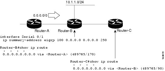
The configuration of the default summary route on Router-B sends a 0.0.0.0/0 summary route to Router-C and blocks all other routes, including the 10.1.1.0/24 route, from being advertised to Router-C. However, this configuration also generates a local discard route--a route for 0.0.0.0/0 on the null 0 interface with an administrative distance of 5--on Router-B. When this route is created, it overrides the EIGRP-learned default route. Router-B will no longer be able to reach destinations that it would normally reach through the 0.0.0.0/0 route.
This problem is resolved by applying a floating summary route to the interface on Router-B that connects to Router-C. The floating summary route is applied by configuring an administrative distance for the default summary route on the interface of Router-B with the following statement for an autonomous system configuration:
Router-B(config-if)# ip summary-address eigrp 100 0.0.0.0 0.0.0.0 250
The floating summary route is applied by configuring an administrative distance for the default summary route on the interface of Router-B with the following statement for a named configuration:
Router-B(config)# router eigrp 1
Router-B(config-router)# address-family ipv4 unicast vrf vrf1 autonomous-system 1
Router-B(config-router-af)# af-interface serial0/1
Router-B(config-router-af-interface)# summary-address eigrp 100 0.0.0.0 0.0.0.0 250
The administrative distance of 250, applied in the summary-address command, is now assigned to the discard route generated on Router-B. The 0.0.0.0/0, from Router-A, is learned through EIGRP and installed in the local routing table. Routing to Router-C is restored.
If Router-A loses the connection to Router-B, Router-B will continue to advertise a default route to Router-C, which allows traffic to continue to reach destinations attached to Router-B. However, traffic destined to networks connected to Router-A or behind Router-A will be dropped when the traffic reaches Router-B.
The figure below shows a network with two connections from the core, Router-A and Router-D. Both Router-B and Router-E have floating summary routes configured on the interfaces connected to Router-C. If the connection between Router-E and Router-C fails, the network will continue to operate normally. All traffic will flow from Router-C through Router-B to hosts attached to Router-A and Router-D.

However, if the link between Router-A and Router-B fails, the network may incorrectly direct traffic because Router-B will continue to advertise the default route (0.0.0.0/0) to Router-C. In this scenario, Router-C still forwards traffic to Router-B, but Router-B drops the traffic. To avoid this problem, you should configure the summary address with an administrative distance only on single-homed remote devices or areas that have only one exit point between two segments of the network. If two or more exit points exist (from one segment of the network to another), configuring the floating default route can result in the formation of a black hole route (a route that has quick packet dropping capabilities).
EIGRP Route Authentication
EIGRP route authentication provides MD5 authentication of routing updates from the EIGRP routing protocol. The MD5 keyed digest in each EIGRP packet prevents the introduction of unauthorized or false routing messages from unapproved sources.
Each key has its own key identifier (specified with the key number key chain configuration command), which is stored locally. The combination of the key identifier and the interface associated with the message uniquely identifies the authentication algorithm and the MD5 authentication key in use.
You can configure multiple keys with specific lifetimes. Only one authentication packet is sent, regardless of how many valid keys exist. The software examines the key numbers in the order from lowest to highest, and uses the first valid key it encounters. Note that the router needs to know the time to configure keys with lifetimes. Refer to the Network Time Protocol (NTP) and calendar commands in the Performing Basic System Management module of the Network Management Configuration Guide.
Hello Packets and the Hold-Time Intervals
You can adjust the interval between hello packets and the hold time. Hello packets and hold-time intervals are protocol-independent parameters that work for IP and Internetwork Packet Exchange (IPX).
Routing devices periodically send hello packets to each other to dynamically learn of other devices on their directly attached networks. This information is used to discover neighbors and to learn when neighbors become unreachable or inoperative.
By default, hello packets are sent every 5 seconds. The exception is on low-speed, nonbroadcast multiaccess (NBMA) media, where the default hello interval is 60 seconds. Low speed is considered to be a rate of T1 or slower, as specified with the bandwidth interface configuration command. The default hello interval remains 5 seconds for high-speed NBMA networks. Note that for the purposes of EIGRP, Frame Relay and Switched Multimegabit Data Service (SMDS) networks may or may not be considered to be NBMA. These networks are considered NBMA only if the interface has not been configured to use physical multicasting.
You can configure the hold time on a specified interface for a particular EIGRP routing process designated by the autonomous system number. The hold time is advertised in hello packets and indicates to neighbors the length of time they should consider the sender valid. The default hold time is three times the hello interval or 15 seconds. For slow-speed NBMA networks, the default hold time is 180 seconds.
On very congested and large networks, the default hold time might not be sufficient for all devices to receive hello packets from their neighbors. In such cases, you may want to increase the hold time.
Note | Do not adjust the hold time without informing your technical support personnel. |
Split Horizon
Split horizon controls the sending of EIGRP update and query packets. Split horizon is a protocol-independent parameter that works for IP and IPX. When split horizon is enabled on an interface, update and query packets are not sent to destinations for which this interface is the next hop. Controlling update and query packets in this manner reduces the possibility of routing loops.
By default, split horizon is enabled on all interfaces.
Split horizon blocks route information from being advertised by a router out of any interface from which that information originated. This behavior usually optimizes communications among multiple routing devices, particularly when links are broken. However, with nonbroadcast networks (such as Frame Relay and SMDS), situations can arise for which this behavior is less than ideal. In such situations and in networks that have EIGRP configured, you may want to disable split horizon.
EIGRP Dual DMVPN Domain Enhancement
The EIGRP Dual DMVPN Domain Enhancement feature supports the no next-hop self command on dual Dynamic Multipoint VPN (DMVPN) domains in both IPv4 and IPv6 configurations.
EIGRP, by default, sets the local outbound interface as the next-hop value while advertising a network to a peer, even when advertising routes out of the interface on which the routes were learned. This default setting can be disabled by using the no ip next-hop-self command in autonomous system configurations or the no next-hop-self command in named configurations. When the next-hop self command is disabled, EIGRP does not advertise the local outbound interface as the next hop if the route has been learned from the same interface. Instead, the received next-hop value is used to advertise learned routes. However, this functionality only evaluates the first entry in the EIGRP table. If the first entry shows that the route being advertised is learned on the same interface, then the received next hop is used to advertise the route. The no next-hop-self configuration ignores subsequent entries in the table, which may result in the no-next-hop-self configuration being dishonored on other interfaces.
The EIGRP Dual DMVPN Domain Enhancement feature introduces the no-ecmp-mode keyword, which is an enhancement to the no next-hop-self and no ip next-hop-self commands. When this keyword is used, all routes to a network in the EIGRP table are evaluated to check whether routes advertised from an interface were learned on the same interface. If a route advertised by an interface was learned on the same interface, the no next-hop-self configuration is honored and the received next hop is used to advertise this route.
Link Bandwidth Percentage
By default, EIGRP packets consume a maximum of 50 percent of the link bandwidth when configured with the bandwidth interface configuration command for autonomous system configurations and with the bandwidth-percent command for named configurations. You might want to change the bandwidth value if a different level of link utilization is required or if the configured bandwidth does not match the actual link bandwidth (which may have been configured to influence route metric calculations). This is a protocol-independent parameter that works for IP and IPX.
EIGRP Stub Routing
The EIGRP Stub Routing feature improves network stability, reduces resource utilization, and simplifies the stub device configuration.
Stub routing is commonly used in hub-and-spoke network topologies. In a hub-and-spoke network, one or more end (stub) networks are connected to a remote device (the spoke) that is connected to one or more distribution devices (the hub). The remote device is adjacent to one or more distribution devices. The only route for IP traffic to reach the remote device is through a distribution device. This type of configuration is commonly used in WAN topologies, where the distribution device is directly connected to a WAN. The distribution device can be connected to many remote devices, which is often the case. In a hub-and-spoke topology, the remote device must forward all nonlocal traffic to a distribution device, so it becomes unnecessary for the remote device to have a complete routing table. Generally, the distribution device need not send anything more than a default route to the remote device.
When using the EIGRP Stub Routing feature, you need to configure the distribution and remote devices to use EIGRP and configure only the remote device as a stub. Only specified routes are propagated from the remote (stub) device. The stub device responds to all queries for summaries, connected routes, redistributed static routes, external routes, and internal routes with the message "inaccessible." A device that is configured as a stub will send a special peer information packet to all neighboring devices to report its status as a stub device.
Any neighbor that receives a packet informing it of the stub status will not query the stub device for any routes, and a device that has a stub peer will not query that peer. The stub device will depend on the distribution device to send proper updates to all peers.
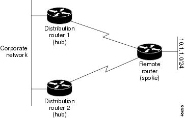
The figure below shows a simple hub-and-spoke network.

The stub routing feature by itself does not prevent routes from being advertised to the remote device. In the above example, the remote device (in this case a router) can access the corporate network and the Internet only through the distribution device (in this case a router). Having a complete route table on the remote router would serve no functional purpose because the path to the corporate network and the Internet would always be through the distribution router. The large route table would only reduce the amount of memory required by the remote router. Bandwidth and memory can be conserved by summarizing and filtering routes in the distribution router. The remote router need not receive routes that have been learned from other networks because the remote router must send all nonlocal traffic, regardless of the destination, to the distribution router. If a true stub network is desired, the distribution router should be configured to send only a default route to the remote router. The EIGRP Stub Routing feature does not automatically enable summarization on distribution devices. In most cases, the network administrator will need to configure summarization on distribution devices.
Without the EIGRP Stub Routing feature, even after routes that are sent from the distribution device to the remote device have been filtered or summarized, a problem might occur. If a route is lost somewhere in the corporate network, EIGRP could send a query to the distribution device, which in turn would send a query to the remote device, even if routes are being summarized. If there is a communication problem (over the WAN link) between the distribution device and the remote device, an EIGRP stuck in active (SIA) condition could occur and cause instability elsewhere in the network. The EIGRP Stub Routing feature allows a network administrator to prevent queries from being sent to the remote device.
Dual-Homed Remote Topology
In addition to a simple hub-and-spoke network, where a remote device is connected to a single distribution device, the remote device can be dual-homed to two or more distribution devices. This configuration adds redundancy and introduces unique issues, and the stub feature helps to address some of these issues.
A dual-homed remote device will have two or more distribution (hub) devices. However, the principles of stub routing are the same as they are with a hub-and-spoke topology. The figure below shows a common dual-homed remote topology with one remote device--a router, but 100 or more routers could be connected on the same interfaces on distribution router 1 and distribution router 2. The remote router will use the best route to reach its destination. If distribution router 1 experiences a failure, the remote router can still use distribution router 2 to reach the corporate network.
The figure above shows a simple dual-homed remote topology with one remote router and two distribution routers. Both distribution routers maintain routes to the corporate network and stub network 10.1.1.0/24.
Dual-homed routing can introduce instability into an EIGRP network. In the figure below, distribution router 1 is directly connected to network 10.3.1.0/24. If summarization or filtering is applied on distribution router 1, the router will advertise network 10.3.1.0/24 to all of its directly connected EIGRP neighbors (distribution router 2 and the remote router).
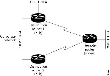
The figure above shows a simple dual-homed remote topology, where distribution router 1 is connected to both network 10.3.1.0/24 and network 10.2.1.0/24.
If the 10.2.1.0/24 link between distribution router 1 and distribution router 2 fails, the lowest cost path to network 10.3.1.0/24 from distribution router 2 will be through the remote router (see the figure below). This route is not desirable because the traffic that was previously traveling across the corporate network 10.2.1.0/24 would now be sent across a much lower bandwidth connection. The overutilization of the lower bandwidth WAN connection can cause many problems that might affect the entire corporate network. The use of the lower bandwidth route that passes through the remote router may cause WAN EIGRP distribution routers to be dropped. Serial lines on distribution and remote routers may also be dropped, and EIGRP SIA errors on the distribution and core routers can occur.
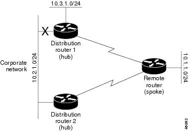
It is not desirable for traffic from distribution router 2 to travel through any remote router to reach network 10.3.1.0/24. Backup routes can be used if links are sized to manage the load. However, most networks, of the type shown in the figure above, have remote devices located at remote offices with relatively slow links. To ensure that traffic from distribution devices are not routed through a remote device, you can configure route summarization on the distribution device and the remote device.
It is typically undesirable for traffic from a distribution device to use a remote device as a transit path. A typical connection from a distribution device to a remote device would have much less bandwidth than a connection at the network core. Attempting to use a remote device with a limited bandwidth connection as a transit path would generally produce excessive congestion at the remote device. The EIGRP Stub Routing feature can prevent this problem by preventing the remote device from advertising core routes back to the distribution devices. In the above example, routes learned by the remote router from distribution router 1 will not be advertised to distribution router 2. Therefore, distribution router 2 will not use the remote router as a transit for traffic destined to the network core.
The EIGRP Stub Routing feature provides network stability. If the network is not stable, this feature prevents EIGRP queries from being sent over limited bandwidth links to nontransit devices. Instead, distribution devices to which the stub device is connected answer queries on behalf of the stub device. This feature greatly reduces the chance of further network instability due to congested or problematic WAN links. The EIGRP Stub Routing feature also simplifies the configuration and maintenance of hub-and-spoke networks. When stub routing is enabled in dual-homed remote configurations, it is no longer necessary to configure filtering on remote devices to prevent those devices from appearing as transit paths to hub devices.

EIGRP Stub Routing Leak Map Support
In EIGRP stub routing configurations where there is a remote site with more than one device, only one of the remote devices can be configured as the stub device. If you have two distribution layer devices and two devices at a remote site, there is no way to declare both remote devices as stub devices. If one remote device is configured as a stub device, the other remote device can neither learn routes towards the network core if the link between the stub device and the distribution layer device fails nor route around the failed link.
The stub device cannot readvertise routes learned from any neighboring EIGRP device. To resolve this issue, a leak map configuration that allows a selected set of learned routes to be readvertised to other peers can be added to the EIGRP stub routing feature. The set of routes allowed through the stub device are specified using a standard route map so that routes can be matched based on tags, prefixes, or interfaces. These routes are marked using the site-of-origin code mechanism, which prevents routes permitted through the stub from being readvertised into the core of the network.
Use the eigrp stub leak-map command to configure the EIGRP stub routing feature to reference a leak map that identifies routes that are allowed to be advertised on an EIGRP stub device that would normally have been suppressed.
How to Configure EIGRP
- Enabling EIGRP Autonomous System Configuration
- Enabling the EIGRP Named Configuration
- Enabling the EIGRP IPv6 VRF-Lite Named Configuration
- Configuring Optional EIGRP Parameters in an Autonomous System Configuration
- Configuring Optional EIGRP Parameters in a Named Configuration
- Configuring the EIGRP Redistribution Autonomous System Configuration
- Configuring the EIGRP Route Summarization Autonomous System Configuration
- Configuring the EIGRP Route Summarization Named Configuration
- Configuring the EIGRP Event Logging Autonomous System Configuration
- Configuring the EIGRP Event Logging Named Configuration
- Configuring Equal and Unequal Cost Load Balancing Autonomous System Configuration
- Configuring Equal and Unequal Cost Load Balancing Named Configuration
- Configuring the EIGRP Route Authentication Autonomous System Configuration
- Configuring the EIGRP Route Authentication Named Configuration
- Adjusting the Interval Between Hello Packets and the Hold Time in an Autonomous System Configuration
- Adjusting the Interval Between Hello Packets and the Hold Time in a Named Configuration
- Disabling the Split Horizon Autonomous System Configuration
- Disabling the Split Horizon and Next-Hop-Self Named Configuration
- Configuring the EIGRP Stub Routing Autonomous System Configuration
- Configuring the EIGRP Stub Routing Named Configuration
- Configuring vNET Commands in an EIGRP Autonomous System
- Configuring vNET Commands in EIGRP Named Mode
- Monitoring and Maintaining the EIGRP Autonomous System Configuration
- Monitoring and Maintaining the EIGRP Named Configuration
Enabling EIGRP Autonomous System Configuration
Perform this task to enable EIGRP and create an EIGRP routing process. EIGRP sends updates to interfaces in specified networks. If you do not specify the network of an interface, the interface will not be advertised in any EIGRP update.
Configuring the router eigrp autonomous-system-number command creates an EIGRP autonomous system configuration that creates an EIGRP routing instance, which can be used for tagging routing information.
DETAILED STEPS
Enabling the EIGRP Named Configuration
Perform this task to enable EIGRP and to create an EIGRP routing process. EIGRP sends updates to interfaces in specified networks. If you do not specify the network of an interface, the interface will not be advertised in any EIGRP update.
Configuring the router eigrp virtual-instance-name command creates an EIGRP named configuration. The EIGRP named configuration does not create an EIGRP routing instance by itself. The EIGRP named configuration is the base configuration, which is required to define address family configurations used for routing.
DETAILED STEPS
Enabling the EIGRP IPv6 VRF-Lite Named Configuration
DETAILED STEPS
Configuring Optional EIGRP Parameters in an Autonomous System Configuration
Perform this task to configure optional EIGRP parameters, which include applying offsets to routing metrics, adjusting EIGRP metrics, and disabling automatic summarization in an EIGRP autonomous system configuration.
DETAILED STEPS
Configuring Optional EIGRP Parameters in a Named Configuration
Perform this task to configure optional EIGRP named configuration parameters, which includes applying offsets to routing metrics, adjusting EIGRP metrics, setting the RIB-scaling factor, and disabling automatic summarization.
DETAILED STEPS
| Command or Action | Purpose | |||
|---|---|---|---|---|
Step 1 |
enable
Example: Device> enable |
Enables privileged EXEC mode. | ||
Step 2 |
configure
terminal
Example: Device# configure terminal |
Enters global configuration mode. | ||
Step 3 |
router
eigrp
virtual-instance-name
Example: Device(config)# router eigrp virtual-name1 |
Enables an EIGRP routing process and enters router configuration mode. | ||
Step 4 | Enter one of the following:
Example: Device(config-router)# address-family ipv4 autonomous-system 45000 Device(config-router)# address-family ipv6 autonomous-system 45000 |
Enters address family configuration mode to configure an EIGRP IPv4 or IPv6 routing instance. | ||
Step 5 |
network
ip-address
[wildcard-mask]
Example: Device(config-router-af)# network 172.16.0.0 |
Specifies a network for the EIGRP routing process. | ||
Step 6 |
metric
weights
tos
k1
k2
k3
k4
k5
k6
Example: Device(config-router-af)# metric weights 0 2 0 2 0 0 0 |
(Optional) Adjusts the EIGRP metric or K value.
| ||
Step 7 |
af-interface {default |
interface-type
interface-number}
Example: Device(config-router-af)# af-interface gigabitethernet 0/0/1 |
Enters address family interface configuration mode and configures interface-specific EIGRP commands. | ||
Step 8 |
passive-interface
Example: Device(config-router-af-interface)# passive-interface |
Suppresses EIGRP hello packets and routing updates on interfaces while still including the interface addresses in the topology database. | ||
Step 9 |
bandwidth-percent
maximum-bandwidth-percentage
Example: Device(config-router-af-interface)# bandwidth-percent 75 |
Configures the percentage of bandwidth that may be used by an EIGRP address family on an interface. | ||
Step 10 |
exit-af-interface
Example: Device(config-router-af-interface)# exit-af-interface |
Exits address family interface configuration mode. | ||
Step 11 |
topology {base |
topology-name
tid
number}
Example: Device(config-router-af)# topology base |
Configures an EIGRP process to route IP traffic under the specified topology instance and enters address family topology configuration mode. | ||
Step 12 |
offset-list [access-list-number |
access-list-name] {in |
out}
offset [interface-type
interface-number]
Example: Device(config-router-af-topology)# offset-list 21 in 10 gigabitethernet 6/2 |
(Optional) Applies an offset to routing metrics. | ||
Step 13 |
no
auto-summary
Example: Device(config-router-af-topology)# no auto-summary |
(Optional) Disables automatic summarization.
| ||
Step 14 |
end
Example: Device(config-router-af-topology)# end |
Returns to privileged EXEC mode. |
Configuring the EIGRP Redistribution Autonomous System Configuration
Perform this task to configure redistribution of non-EIGRP protocol metrics into EIGRP metrics and to configure the EIGRP administrative distance in an EIGRP autonomous system configuration.
You must use a default metric to redistribute a protocol into EIGRP, unless you use the redistribute command.
Note | Metric defaults have been carefully set to work for a wide variety of networks. Take great care when changing these values. |
Default metrics are supported only when you are redistributing from EIGRP or static routes.
An administrative distance is a rating of the trustworthiness of a routing information source, such as an individual router or a group of routers. Numerically, an administrative distance is an integer from 0 to 255. In general, the higher the value the lower the trust rating. An administrative distance of 255 means the routing information source cannot be trusted at all and should be ignored.
DETAILED STEPS
| Command or Action | Purpose | |
|---|---|---|
Step 1 |
enable
Example: Device> enable |
Enables privileged EXEC mode. |
Step 2 |
configure
terminal
Example: Device# configure terminal |
Enters global configuration mode. |
Step 3 |
router
eigrp
autonomous-system
Example: Device(config)# router eigrp 1 |
Enables an EIGRP routing process and enters router configuration mode. |
Step 4 |
network
ip-address
[wildcard-mask]
Example: Device(config-router)# network 172.16.0.0 |
Associates networks with an EIGRP routing process. |
Step 5 |
redistribute
protocol
[process-id] {level-1 |
level-1-2
|
level-2} [autonomous-system-number] [metric {metric-value
|
transparent}] [metric-type
type-value] [match {internal |
external
1
|
external
2}] [tag
tag-value] [route-map
map-tag] [subnets]
Example: Device(config-router)# redistribute rip level1 |
Redistributes routes from one routing domain into another routing domain. |
Step 6 |
distance
eigrp
internal-distance
external-distance
Example: Device(config-router)# distance eigrp 80 130 |
Allows the use of two administrative distances--internal and external. |
Step 7 |
default-metric
bandwidth
delay
reliability
loading
mtu
Example: Device(config-router)# default-metric 1000 100 250 100 1500 |
Sets metrics for EIGRP. |
Step 8 |
end
Example: Device(config-router)# end |
Exits router configuration mode and returns to privileged EXEC mode. |
Configuring the EIGRP Route Summarization Autonomous System Configuration
Perform this task to configure EIGRP to perform automatic summarization of subnet routes into network-level routes in an EIGRP autonomous system configuration.
DETAILED STEPS
| Command or Action | Purpose | |
|---|---|---|
Step 1 |
enable
Example: Device> enable |
Enables privileged EXEC mode. |
Step 2 |
configure
terminal
Example: Device# configure terminal |
Enters global configuration mode. |
Step 3 |
router
eigrp
autonomous-system
Example: Device(config)# router eigrp 101 |
Enables an EIGRP routing process and enters router configuration mode. |
Step 4 |
exit
Example: Device(config-router)# exit |
Exits router configuration mode. |
Step 5 |
interface
type
number
Example: Device(config)# interface gigabitethernet 0/0/1 |
Enters interface configuration mode. |
Step 6 |
ip
summary-address
eigrp
as-number
ip-address
mask
[admin-distance] [leak-map
name]
Example: Device(config-if)# ip summary-address eigrp 100 10.0.0.0 0.0.0.0 |
(Optional) Configures a summary aggregate address. |
Step 7 |
ip
bandwidth-percent
eigrp
as-number
percent
Example: Device(config-if)# ip bandwidth-percent eigrp 209 75 |
(Optional) Configures the percentage of bandwidth that may be used by EIGRP on an interface. |
Step 8 |
end
Example: Device(config-if)# end |
Exits interface configuration mode and returns to privileged EXEC mode. |
Configuring the EIGRP Route Summarization Named Configuration
Perform this task to configure EIGRP to perform automatic summarization of subnet routes into network-level routes in an EIGRP named configuration.
DETAILED STEPS
| Command or Action | Purpose | |
|---|---|---|
Step 1 |
enable
Example: Device> enable |
Enables privileged EXEC mode. |
Step 2 |
configure
terminal
Example: Device# configure terminal |
Enters global configuration mode. |
Step 3 |
router
eigrp
virtual-instance-name
Example: Device(config)# router eigrp virtual-name1 |
Enables an EIGRP routing process and enters router configuration mode. |
Step 4 | Enter one of the following:
Example: Device(config-router)# address-family ipv4 autonomous-system 45000 Device(config-router)# address-family ipv6 autonomous-system 45000 |
Enters address family configuration mode to configure an EIGRP IPv4 or IPv6 routing instance. |
Step 5 |
af-interface
{default
|
interface-type
interface-number}
Example: Device(config-router-af)# af-interface gigabitethernet 0/0/1 |
Enters address family interface configuration mode and configures interface-specific EIGRP commands. |
Step 6 |
summary-address
ip-address
mask
[administrative-distance [leak-map
leak-map-name]]
Example: Device(config-router-af-interface)# summary-address 192.168.0.0 255.255.0.0 |
Configures a summary address for EIGRP. |
Step 7 |
exit-af-interface
Example: Device(config-router-af-interface)# exit-af-interface |
Exits address family interface configuration mode. |
Step 8 |
topology
{base |
topology-name
tid
number}
Example: Device(config-router-af)# topology base |
Configures an EIGRP process to route IP traffic under the specified topology instance and enters address family topology configuration mode. |
Step 9 |
summary-metric
network-address
subnet-mask
bandwidth
delay
reliability
load
mtu
Example: Device(config-router-af-topology)# summary-metric 192.168.0.0/16 10000 10 255 1 1500 |
(Optional) Configures a fixed metric for an EIGRP summary aggregate address. |
Step 10 |
end
Example: Device(config-router-af-topology)# end |
Exits address family topology configuration mode and returns to privileged EXEC mode. |
Configuring the EIGRP Event Logging Autonomous System Configuration
DETAILED STEPS
| Command or Action | Purpose | |
|---|---|---|
Step 1 |
enable
Example: Device> enable |
Enables privileged EXEC mode. |
Step 2 |
configure
terminal
Example: Device# configure terminal |
Enters global configuration mode. |
Step 3 |
router
eigrp
autonomous-system
Example: Device(config)# router eigrp 101 |
Enables an EIGRP routing process and enters router configuration mode. |
Step 4 |
eigrp
event-log-size
size
Example: Device(config-router)# eigrp event-log-size 5000010 |
(Optional) Sets the size of the EIGRP event log. |
Step 5 |
eigrp
log-neighbor-changes
Example: Device(config-router)# eigrp log-neighbor-changes |
(Optional) Enables logging of EIGRP neighbor adjacency changes. |
Step 6 |
eigrp
log-neighbor-warnings
[seconds]
Example: Device(config-router)# eigrp log-neighbor-warnings 300 |
(Optional) Enables the logging of EIGRP neighbor warning messages. |
Step 7 |
end
Example: Device(config-router)# end |
Exits router configuration mode and returns to privileged EXEC mode. |
Configuring the EIGRP Event Logging Named Configuration
DETAILED STEPS
| Command or Action | Purpose | |
|---|---|---|
Step 1 |
enable
Example: Device> enable |
Enables privileged EXEC mode. |
Step 2 |
configure
terminal
Example: Device# configure terminal |
Enters global configuration mode. |
Step 3 |
router
eigrp
virtual-instance-name
Example: Device(config)# router eigrp virtual-name1 |
Enables an EIGRP routing process and enters router configuration mode. |
Step 4 | Enter one of the following:
Example: Device(config-router)# address-family ipv4 autonomous-system 45000 Device(config-router)# address-family ipv6 autonomous-system 45000 |
Enters address family configuration mode to configure an EIGRP IPv4 or IPv6 routing instance. |
Step 5 |
eigrp
log-neighbor-warnings
[seconds]
Example: Device(config-router-af)# eigrp log-neighbor-warnings 300 |
(Optional) Enables the logging of EIGRP neighbor warning messages. |
Step 6 |
eigrp
log-neighbor-changes
Example: Device(config-router-af)# eigrp log-neighbor-changes |
(Optional) Enables logging of EIGRP neighbor adjacency changes. |
Step 7 |
topology
{base |
topology-name
tid
number}
Example: Device(config-router-af)# topology base |
Configures an EIGRP process to route IP traffic under the specified topology instance and enters address family topology configuration mode. |
Step 8 |
eigrp
event-log-size
size
Example: Device(config-router-af-topology)# eigrp event-log-size 10000 |
(Optional) Sets the size of the EIGRP event log. |
Step 9 |
end
Example: Device(config-router-af-topology)# end |
Exits address family topology configuration mode and returns to privileged EXEC mode. |
Configuring Equal and Unequal Cost Load Balancing Autonomous System Configuration
DETAILED STEPS
| Command or Action | Purpose | |
|---|---|---|
Step 1 |
enable
Example: Device> enable |
Enables privileged EXEC mode. |
Step 2 |
configure
terminal
Example: Device# configure terminal |
Enters global configuration mode. |
Step 3 |
router
eigrp
autonomous-system
Example: Device(config)# router eigrp 101 |
Enables an EIGRP routing process and enters router configuration mode. |
Step 4 |
traffic-share
balanced
Example: Device(config-router)# traffic-share balanced |
Controls how traffic is distributed among routes when multiple routes for the same destination network have different costs. |
Step 5 |
maximum-paths
number-of-paths
Example: Device(config-router)# maximum-paths 5 |
Controls the maximum number of parallel routes that an IP routing protocol can support. |
Step 6 |
variance
multiplier
Example: Device(config-router)# variance 1 |
Controls load balancing in an internetwork based on EIGRP. |
Step 7 |
end
Example: Device(config-router)# end |
Exits router configuration mode and returns to privileged EXEC mode. |
Configuring Equal and Unequal Cost Load Balancing Named Configuration
DETAILED STEPS
| Command or Action | Purpose | |
|---|---|---|
Step 1 |
enable
Example: Device> enable |
Enables privileged EXEC mode. |
Step 2 |
configure
terminal
Example: Device# configure terminal |
Enters global configuration mode. |
Step 3 |
router
eigrp
virtual-instance-name
Example: Device(config)# router eigrp virtual-name1 |
Enables an EIGRP routing process and enters router configuration mode. |
Step 4 | Enter one of the following:
Example: Device(config-router)# address-family ipv4 autonomous-system 45000 Device(config-router)# address-family ipv6 autonomous-system 45000 |
Enters address family configuration mode to configure an EIGRP IPv4 or IPv6 routing instance. |
Step 5 |
topology
{base |
topology-name
tid
number}
Example: Device(config-router-af)# topology base |
Configures an EIGRP process to route IP traffic under the specified topology instance and enters address family topology configuration mode. |
Step 6 |
traffic-share
balanced
Example: Device(config-router-af-topology)# traffic-share balanced |
Controls how traffic is distributed among routes when multiple routes for the same destination network have different costs. |
Step 7 |
maximum-paths
number-of-paths
Example: Device(config-router-af-topology)# maximum-paths 5 |
Controls the maximum number of parallel routes that an IP routing protocol can support. |
Step 8 |
variance
multiplier
Example: Device(config-router-af-topology)# variance 1 |
Controls load balancing in an internetwork based on EIGRP. |
Step 9 |
end
Example: Device(config-router-af-topology)# end |
Exits address family topology configuration mode and returns to privileged EXEC mode. |
Configuring the EIGRP Route Authentication Autonomous System Configuration
DETAILED STEPS
| Command or Action | Purpose | |
|---|---|---|
Step 1 |
enable
Example: Device> enable |
Enables privileged EXEC mode. |
Step 2 |
configure
terminal
Example: Device# configure terminal |
Enters global configuration mode. |
Step 3 |
interface
type
number
Example: Device(config)# interface gigabitethernet 0/0/1 |
Configures an interface type and enters interface configuration mode. |
Step 4 |
ip
authentication
mode
eigrp
autonomous-system
md5
Example: Device(config-if)# ip authentication mode eigrp 1 md5 |
Enables MD5 authentication in EIGRP packets. |
Step 5 |
ip
authentication
key-chain
eigrp
autonomous-system
key-chain
Example: Device(config-if)# ip authentication key-chain eigrp 1 keychain1 |
Enables authentication of EIGRP packets. |
Step 6 |
exit
Example: Device(config-if)# exit |
Exits to global configuration mode. |
Step 7 |
key
chain
name-of-chain
Example: Device(config)# key chain keychain1 |
Identifies a key chain and enters key chain configuration mode. |
Step 8 |
key
key-id
Example: Device(config-keychain)# key 1 |
Identifies the key number and enters key chain key configuration mode. |
Step 9 |
key-string
text
Example: Device(config-keychain-key)# key-string 0987654321 |
Identifies the key string. |
Step 10 |
accept-lifetime
start-time
{infinite |
end-time |
duration
seconds}
Example: Device(config-keychain-key)# accept-lifetime 04:00:00 Jan 4 2007 infinite |
(Optional) Specifies the time period during which the key can be received. |
Step 11 |
send-lifetime
start-time
{infinite |
end-time |
duration
seconds}
Example: Device(config-keychain-key)# send-lifetime 04:00:00 Dec 4 2006 infinite |
(Optional) Specifies the time period during which the key can be sent. |
Step 12 |
end
Example: Device(config-keychain-key)# end |
Exits key chain key configuration mode and returns to privileged EXEC mode. |
Configuring the EIGRP Route Authentication Named Configuration
DETAILED STEPS
| Command or Action | Purpose | |
|---|---|---|
Step 1 |
enable
Example: Device> enable |
Enables privileged EXEC mode. |
Step 2 |
configure
terminal
Example: Device# configure terminal |
Enters global configuration mode. |
Step 3 |
router
eigrp
virtual-instance-name
Example: Device(config)# router eigrp virtual-name1 |
Enables an EIGRP routing process and enters router configuration mode. |
Step 4 | Enter one of the following:
Example: Router(config-router)# address-family ipv4 autonomous-system 45000 Router(config-router)# address-family ipv6 autonomous-system 45000 |
Enters address family configuration mode to configure an EIGRP IPv4 or IPv6 routing instance. |
Step 5 |
network
ip-address
[wildcard-mask]
Example: Device(config-router-af)# network 172.16.0.0 |
Associates networks with an EIGRP routing process. |
Step 6 |
af-interface
{default |
interface-type
interface-number}
Example: Device(config-router-af)# af-interface ethernet 0/0 |
Enters address family interface configuration mode and configures interface-specific EIGRP commands. |
Step 7 |
authentication
key-chain
name-of-chain
Example: Device(config-router-af-interface)# authentication key-chain SITE1 |
Specifies an authentication key chain for EIGRP. |
Step 8 |
authentication
mode
{hmac-sha-256
encryption-type
password |
md5}
Example: Device(config-router-af-interface)# authentication mode md5 |
Specifies the type of authentication used in an EIGRP address family for the EIGRP instance. |
Step 9 |
exit-af-interface
Example: Device(config-router-af-interface)# exit-af-interface |
Exits address family interface configuration mode. |
Step 10 |
exit-address-family
Example: Device(config-router-af)# exit-address-family |
Exits address family configuration mode. |
Step 11 |
exit
Example: Device(config-router)# exit |
Exits router configuration mode and returns to global configuration mode. |
Step 12 |
key
chain
name-of-chain
Example: Device(config)# key chain keychain1 |
Identifies a key chain and enters key chain configuration mode. |
Step 13 |
key
key-id
Example: Device(config-keychain)# key 1 |
Identifies the key number and enters key chain key configuration mode. |
Step 14 |
key-string
text
Example: Device(config-keychain-key)# key-string 0987654321 |
Identifies the key string. |
Step 15 |
accept-lifetime
start-time
{infinite |
end-time |
duration
seconds}
Example: Device(config-keychain-key)# accept-lifetime 04:00:00 Jan 4 2007 infinite |
(Optional) Specifies the time period during which the key can be received. |
Step 16 |
send-lifetime
start-time
{infinite |
end-time |
duration
seconds}
Example: Device(config-keychain-key)# send-lifetime 04:00:00 Dec 4 2006 infinite |
(Optional) Specifies the time period during which the key can be sent. |
Step 17 |
end
Example: Device(config-keychain-key)# end |
Exits key chain key configuration mode and returns to privileged EXEC mode. |
Adjusting the Interval Between Hello Packets and the Hold Time in an Autonomous System Configuration
DETAILED STEPS
| Command or Action | Purpose | |||
|---|---|---|---|---|
Step 1 |
enable
Example: Device> enable |
Enables privileged EXEC mode. | ||
Step 2 |
configure
terminal
Example: Device# configure terminal |
Enters global configuration mode. | ||
Step 3 |
router
eigrp
autonomous-system-number
Example: Device(config)# router eigrp 101 |
Enables an EIGRP routing process and enters router configuration mode. | ||
Step 4 |
exit
Example: Device(config-router)# exit |
Exits to global configuration mode. | ||
Step 5 |
interface
type number
Example: Device(config)# interface gigabitethernet 0/1/1 |
Enters interface configuration mode. | ||
Step 6 |
ip
hello-interval
eigrp
autonomous-system-number
seconds
Example: Device(config-if)# ip hello-interval eigrp 109 10 |
Configures the hello interval for an EIGRP routing process. | ||
Step 7 |
ip
hold-time
eigrp
autonomous-system-number
seconds
Example: Device(config-if)# ip hold-time eigrp 109 40 |
Configures the hold time for an EIGRP routing process.
| ||
Step 8 |
end
Example: Device(config-if)# end |
Exits interface configuration mode and returns to privileged EXEC mode. |
Adjusting the Interval Between Hello Packets and the Hold Time in a Named Configuration
DETAILED STEPS
| Command or Action | Purpose | |
|---|---|---|
Step 1 |
enable
Example: Device> enable |
Enables privileged EXEC mode. |
Step 2 |
configure
terminal
Example: Device# configure terminal |
Enters global configuration mode. |
Step 3 |
router
eigrp
virtual-instance-name
Example: Device(config)# router eigrp virtual-name1 |
Enables an EIGRP routing process and enters router configuration mode. |
Step 4 | Enter one of the following:
Example: Device(config-router)# address-family ipv4 autonomous-system 45000 Device(config-router)# address-family ipv6 autonomous-system 45000 |
Enters address family configuration mode to configure an EIGRP IPv4 or IPv6 routing instance. |
Step 5 |
af-interface
{default |
interface-type
interface-number}
Example: Device(config-router-af)# af-interface gigabitethernet 0/0/1 |
Enters address family interface configuration mode and configures interface-specific EIGRP commands. |
Step 6 |
hello-interval
seconds
Example: Device(config-router-af-interface)# hello-interval 10 |
Configures the hello interval for an EIGRP address family named configuration. |
Step 7 |
hold-time
seconds
Example: Device(config-router-af-interface)# hold-time 50 |
Configures the hold time for an EIGRP address family named configuration. |
Step 8 |
end
Example: Device(config-router-af-interface)# end |
Exits address family interface configuration mode and returns to privileged EXEC mode. |
Disabling the Split Horizon Autonomous System Configuration
Split horizon controls the sending of EIGRP updates and query packets. When split horizon is enabled on an interface, updates and query packets are not sent for destinations for which this interface is the next hop. Controlling updates and query packets in this manner reduces the possibility of routing loops.
By default, split horizon is enabled on all interfaces.
DETAILED STEPS
| Command or Action | Purpose | |
|---|---|---|
Step 1 |
enable
Example: Device> enable |
Enables privileged EXEC mode. |
Step 2 |
configure
terminal
Example: Device# configure terminal |
Enters global configuration mode. |
Step 3 |
interface
type
number
Example: Device(config)# interface gigabitethernet 0/1 |
Configures an interface and enters interface configuration mode. |
Step 4 |
no
ip
split-horizon
eigrp
autonomous-system-number
Example: Device(config-if)# no ip split-horizon eigrp 101 |
Disables split horizon. |
Step 5 |
end
Example: Device(config-if)# end |
Exits interface configuration mode and returns to privileged EXEC mode. |
Disabling the Split Horizon and Next-Hop-Self Named Configuration
EIGRP, by default, sets the next-hop value to the local outbound interface address for routes that it is advertising, even when advertising those routes back from the same interface from where they were learned. Perform this task to change this default setting and configure EIGRP to use the received next-hop value when advertising these routes. Disabling next-hop-self is primarily useful in DMVPN spoke-to-spoke topologies.
By default, split horizon is enabled on all interfaces.
DETAILED STEPS
| Command or Action | Purpose | |
|---|---|---|
Step 1 |
enable
Example: Device> enable |
Enables privileged EXEC mode. |
Step 2 |
configure
terminal
Example: Device# configure terminal |
Enters global configuration mode. |
Step 3 |
router
eigrp
virtual-instance-name
Example: Device(config)# router eigrp virtual-name1 |
Enables an EIGRP routing process and enters router configuration mode. |
Step 4 | Enter one of the following:
Example: Device(config-router)# address-family ipv4 autonomous-system 45000 Device(config-router)# address-family ipv6 autonomous-system 45000 |
Enters address family configuration mode to configure an EIGRP IPv4 or IPv6 routing instance. |
Step 5 |
af-interface
{default |
interface-type
interface-number}
Example: Device(config-router-af)# af-interface gigabitethernet 0/0/1 |
Enters address family interface configuration mode and configures interface-specific EIGRP commands. |
Step 6 |
no
split-horizon
Example: Device(config-router-af-interface)# no split-horizon |
Disables EIGRP split horizon. |
Step 7 |
no
next-hop-self
[no-ecmp-mode]
Example: Device(config-router-af-interface)# no next-hop-self no-ecmp-mode |
(Optional) Instructs an EIGRP router to use the received next hop rather than the local outbound interface address as the next hop. |
Step 8 |
end
Example: Device(config-router-af-interface)# end |
Exits address family interface configuration mode and returns to privileged EXEC mode. |
Configuring the EIGRP Stub Routing Autonomous System Configuration
DETAILED STEPS
| Command or Action | Purpose | |
|---|---|---|
Step 1 |
enable
Example: Device> enable |
Enables privileged EXEC mode. |
Step 2 |
configure
terminal
Example: Device# configure terminal |
Enters global configuration mode. |
Step 3 |
router
eigrp
autonomous-system-number
Example: Device(config)# router eigrp 1 |
Configures a remote or distribution device to run an EIGRP process and enters router configuration mode. |
Step 4 |
network
ip-address
[wildcard-mask]
Example: Device(config-router)# network 172.16.0.0 |
Specifies the network address of the EIGRP distribution device. |
Step 5 |
eigrp
stub
[receive-only] [leak-map
name] [connected] [static] [summary] [redistributed]
Example: Device(config-router)# eigrp stub connected static |
Configures a remote device as an EIGRP stub device. |
Step 6 |
end
Example: Device(config-router)# end |
Exits router configuration mode and returns to privileged EXEC mode. |
Step 7 |
show
ip
eigrp
neighbors
[interface-type |
as-number |
static |
detail]
Example: Device# show ip eigrp neighbors detail |
(Optional) Verifies that a remote device has been configured as a stub device with EIGRP. |
Configuring the EIGRP Stub Routing Named Configuration
DETAILED STEPS
| Command or Action | Purpose | |
|---|---|---|
Step 1 |
enable
Example: Device> enable |
Enables privileged EXEC mode. |
Step 2 |
configure
terminal
Example: Device# configure terminal |
Enters global configuration mode. |
Step 3 |
router
eigrp
virtual-instance-name
Example: Device(config)# router eigrp virtual-name1 |
Enables an EIGRP routing process and enters router configuration mode. |
Step 4 | Enter one of the following:
Example: Device(config-router)# address-family ipv4 autonomous-system 45000 Device(config-router)# address-family ipv6 autonomous-system 45000 |
Enters address family configuration mode to configure an EIGRP IPv4 or IPv6 routing instance. |
Step 5 |
network
ip-address
[wildcard-mask]
Example: Device(config-router-af)# network 172.16.0.0 |
Specifies the network address of the EIGRP distribution device. |
Step 6 |
eigrp
stub
[receive-only] [leak-map
name] [connected] [static ] [summary] [redistributed]
Example: Device(config-router-af) eigrp stub leak-map map1 |
Configures a device as a stub using EIGRP. |
Step 7 |
exit-address-family
Example: Device(config-router-af)# exit-address-family |
Exits address family configuration mode. |
Step 8 |
end
Example: Device(config-router)# end |
Exits router configuration mode and returns to privileged EXEC mode. |
Step 9 |
show
eigrp
address-family
{ipv4 |
ipv6} [vrf
vrf-name] [autonomous-system-number] [multicast] [neighbors]
[static] [detail] [interface-type
interface-number]
Example: Device# show eigrp address-family ipv4 neighbors detail |
(Optional) Displays neighbors discovered by EIGRP. |
Configuring vNET Commands in an EIGRP Autonomous System
Perform this task to configure a vNET trunk interface that connects routers to provide the core interface to transport traffic for multiple virtual networks. Traffic carried over a trunk interface is tagged. This task illustrates how to configure a trunk interface with a base VRF instance and two named VRFs, VRF vrf1 and VRF vrf2, and how to associate a VRF with an EIGRP process.
DETAILED STEPS
| Command or Action | Purpose | |
|---|---|---|
Step 1 |
enable
Example: Router> enable |
Enables privileged EXEC mode. |
Step 2 |
configure
terminal
Example: Router# configure terminal |
Enters global configuration mode. |
Step 3 |
vrf definition
vrf-name
Example: Router(config)# vrf definition vrf1 |
Configures a VRF routing table instance and enters VRF configuration mode. |
Step 4 |
vnet tag
number
Example: Router(config-vrf)# vnet tag 100 |
Specifies the global, numeric tag for the VRF. |
Step 5 |
description
string
Example: Router(config-vrf)# description guest access |
(Optional) Describes a VRF to help the network administrator identify the configuration file. |
Step 6 |
address-family ipv4
Example: Router(config-vrf)# address-family ipv4 |
Enters VRF address family configuration mode to configure a routing session using standard IPv4 address prefixes. |
Step 7 |
exit-address-family
Example: Router(config-vrf-af)# exit-address-family |
Exits VRF address family configuration mode and returns to VRF configuration mode. |
Step 8 |
exit
Example: Router(config-vrf)# exit |
Exits VRF configuration mode and returns to global configuration mode. |
Step 9 |
vrf definition
vrf-name
Example: Router(config)# vrf definition vrf2 |
Configures a VRF routing table instance and enters VRF configuration mode. |
Step 10 |
vnet tag
number
Example: Router(config-vrf)# vnet tag 200 |
Specifies the global, numeric tag for the VRF. |
Step 11 |
description
string
Example: Router(config-vrf)# description finance |
(Optional) Describes a VRF to help the network administrator identify the configuration file. |
Step 12 |
address-family ipv4
Example: Router(config-vrf)# address-family ipv4 |
Enters VRF address family configuration mode to configure a routing session using standard IPv4 address prefixes. |
Step 13 |
exit-address-family
Example: Router(config-vrf-af)# exit-address-family |
Exits VRF address family configuration mode and returns to VRF configuration mode. |
Step 14 |
exit
Example: Router(config-vrf)# exit |
Exits VRF configuration mode and returns to global configuration mode. |
Step 15 |
interface
type number
Example: Router(config)# interface ethernet 0/0 |
Configures an interface type and enters interface configuration mode. |
Step 16 |
ip address
ip-address mask
Example: Router(config-if)# ip address 10.1.1.1 255.0.0.0 |
Sets a primary address for the interface. |
Step 17 |
vnet trunk
[list
vrf-list-name]
Example: Router(config-if)# vnet trunk |
Configures vNET on an interface and creates a vNET subinterface.
|
Step 18 |
ip hello-interval eigrp
as-number seconds
Example: Router(config-if)# ip hello-interval eigrp 1 121 |
Configures an EIGRP IPv4 hello interval on the interface. |
Step 19 |
exit
Example: Router(config-if)# exit |
Exits interface configuration mode and returns to global configuration mode. |
Step 20 |
router eigrp
autonomous-system-number
Example: Router(config)# router eigrp 1 |
Enables an EIGRP routing process and enters router configuration mode. |
Step 21 |
address-family ipv4 [unicast] vrf
vrf-name
[autonomous-system
autonomous-system-number]
Example: Router(config-router)# address-family ipv4 vrf vrf1 autonomous-system 1 |
Enters address family configuration mode to configure an EIGRP IPv4 routing instance. |
Step 22 |
exit-address-family
Example: Router(config-router-af)# exit-address-family |
Exits address family configuration mode and returns to router configuration mode. |
Step 23 |
end
Example: Router(config-router)# end |
Exits router configuration mode and returns to privileged EXEC mode. |
Configuring vNET Commands in EIGRP Named Mode
DETAILED STEPS
| Command or Action | Purpose | |
|---|---|---|
Step 1 |
enable
Example: Router> enable |
Enables privileged EXEC mode. |
Step 2 |
configure
terminal
Example: Router# configure terminal |
Enters global configuration mode. |
Step 3 |
vrf definition
vrf-name
Example: Router(config)# vrf definition vrf1 |
Configures a VRF routing table instance and enters VRF configuration mode. |
Step 4 |
vnet tag
number
Example: Router(config-vrf)# vnet tag 100 |
Specifies the global, numeric tag for the VRF. |
Step 5 |
description
string
Example: Router(config-vrf)# description guest access |
(Optional) Describes a VRF to help the network administrator identify the configuration file. |
Step 6 |
address-family ipv4
Example: Router(config-vrf)# address-family ipv4 |
Enters VRF address family configuration mode to configure a routing session using standard IPv4 address prefixes. |
Step 7 |
exit-address-family
Example: Router(config-vrf-af)# exit-address-family |
Exits VRF address family configuration mode and returns to VRF configuration mode. |
Step 8 |
exit
Example: Router(config-vrf)# exit |
Exits VRF configuration mode and returns to global configuration mode. |
Step 9 |
vrf definition
vrf-name
Example: Router(config)# vrf definition vrf2 |
Configures a VRF routing table instance and enters VRF configuration mode. |
Step 10 |
vnet tag
number
Example: Router(config-vrf)# vnet tag 200 |
Specifies the global, numeric tag for the VRF. |
Step 11 |
description
string
Example: Router(config-vrf)# description finance |
(Optional) Describes a VRF to help the network administrator identify the configuration file. |
Step 12 |
address-family ipv4
Example: Router(config-vrf)# address-family ipv4 |
Enters VRF address family configuration mode to configure a routing session using standard IPv4 address prefixes. |
Step 13 |
exit-address-family
Example: Router(config-vrf-af)# exit-address-family |
Exits VRF address family configuration mode and returns to VRF configuration mode. |
Step 14 |
exit
Example: Router(config-vrf)# exit |
Exits VRF configuration mode and returns to global configuration mode. |
Step 15 |
interface
type number
Example: Router(config)# interface ethernet 0/0 |
Configures an interface type and enters interface configuration mode. |
Step 16 |
ip address
ip-address mask
Example: Router(config-if)# ip address 10.1.1.1 255.0.0.0 |
Sets a primary address for the interface. |
Step 17 |
vnet trunk
[list
vrf-list-name]
Example: Router(config-if)# vnet trunk |
Configures vNET on an interface and creates a vNET subinterface.
|
Step 18 |
ip hello-interval eigrp
as-number seconds
Example: Router(config-if)# ip hello-interval eigrp 1 121 |
Configures an EIGRP IPv4 hello interval on the interface. |
Step 19 |
exit
Example: Router(config-if)# exit |
Exits interface configuration mode and returns to global configuration mode. |
Step 20 |
router eigrp
virtual-instance-name
Example: Router(config)# router eigrp vnet |
Enables an EIGRP routing process and enters router configuration mode. |
Step 21 |
address-family ipv4 [multicast] [unicast] [vrf
vrf-name]
autonomous-system
autonomous-system-number
Example: Router(config-router)# address-family ipv4 unicast autonomous-system 1 |
Enters address family configuration mode to configure an EIGRP IPv4 routing instance. |
Step 22 |
af-interface
{default |
interface-type
interface-number}
Example: Router(config-router-af)# af-interface gigabitethernet 0/0/1 |
Enters address family interface configuration mode and configures interface-specific EIGRP commands. |
Step 23 |
hello-interval
seconds
Example: Router(config-router-af-interface)# hello-interval 121 |
Configures the hello interval for an EIGRP address family named configuration. |
Step 24 |
end
Example: Router(config-router-af-interface)# end |
Exits address family interface configuration mode and returns to privileged EXEC mode. |
Monitoring and Maintaining the EIGRP Autonomous System Configuration
DETAILED STEPS
| Step 1 |
enable
Enables privileged EXEC mode. Enter your password if prompted. Example:
Device# enable
|
| Step 2 |
show
ip
eigrp
[vrf {vrf-name |
*}] [autonomous-system-number]
accounting
Displays prefix accounting information for EIGRP processes. |
| Step 3 |
show
ip
eigrp
events
[starting-event-number
ending-event-number] [type]
Displays the EIGRP event log. |
| Step 4 |
show
ip
eigrp
interfaces
[vrf {vrf-name|
*}] [autonomous-system-number] [type
number] [detail]
Displays information about interfaces that are configured for EIGRP. |
| Step 5 |
show
ip
eigrp
[vrf {vrf-name |
*}] [autonomous-system-number]
neighbors [interface-type |
static |
detail]
Displays neighbors discovered by EIGRP. |
| Step 6 |
show
ip
eigrp
[vrf {vrf-name |
*}] [autonomous-system-number]
topology [ip-address [mask]] | [name] [active |
all-links |
detail-links |
pending |
summary |
zero-successors]
Displays entries in the EIGRP topology table. |
| Step 7 |
show
ip
eigrp
[vrf {vrf-name |
*}] [autonomous-system-number]
traffic
Displays the number of EIGRP packets sent and received. |
Monitoring and Maintaining the EIGRP Named Configuration
This task is optional. Use the commands in any order desired to monitor and maintain the EIGRP named configuration.
DETAILED STEPS
| Step 1 |
enable
Enables privileged EXEC mode. Enter your password if prompted. Example:
Device# enable
|
| Step 2 |
show
eigrp
address-family
{ipv4 |
ipv6} [vrf
vrf-name] [autonomous-system-number] [multicast]
accounting
Displays prefix accounting information for EIGRP processes. Example:
Device# show eigrp address-family ipv4 22 accounting
|
| Step 3 |
show
eigrp
address-family
{ipv4 |
ipv6} [vrf
vrf-name] [autonomous-system-number] [multicast]
events
[starting-event-number
ending-event-number] [errmsg
[starting-event-number
ending-event-number]] [sia
[starting-event-number
ending-event-number]] [type]
Displays information about EIGRP address-family events. Example:
Device# show eigrp address-family ipv4 3 events
|
| Step 4 |
show
eigrp
address-family
{ipv4 |
ipv6} [vrf
vrf-name] [autonomous-system-number] [multicast]
interfaces [detail] [interface-type
interface-number]
Displays information about interfaces that are configured for EIGRP. Example:
Device# show eigrp address-family ipv4 4453 interfaces
|
| Step 5 |
show
eigrp
address-family
{ipv4 |
ipv6} [vrf
vrf-name] [autonomous-system-number] [multicast]
neighbors
[static] [detail] [interface-type
interface-number]
Displays the neighbors that are discovered by EIGRP. Example:
Device# show eigrp address-family ipv4 4453 neighbors
|
| Step 6 |
show
eigrp
address-family
{ipv4 |
ipv6} [vrf
vrf-name] [autonomous-system-number] [multicast]
timers
Displays information about EIGRP timers and expiration times. Example:
Device# show eigrp address-family ipv4 4453 timers
|
| Step 7 |
show
eigrp
address-family
{ipv4 |
ipv6} [vrf
vrf-name] [autonomous-system-number] [multicast]
topology [topology-name] [ip-address] [active] [all-links] [detail-links] [pending] [summary] [zero-successors] [route-type {connected |
external |
internal |
local |
redistributed |
summary |
vpn}]
Displays entries in the EIGRP topology table. Example:
Device# show eigrp address-family ipv4 4453 topology
|
| Step 8 |
show
eigrp
address-family
{ipv4 |
ipv6} [vrf
vrf-name] [autonomous-system-number] [multicast]
traffic
Displays the number of EIGRP packets that are sent and received. Example:
Device# show eigrp address-family ipv4 4453 traffic
|
| Step 9 |
show
eigrp
plugins
[plugin-name] [detailed]
Displays general information, including the versions of the EIGRP protocol features that are currently running on the device. Example:
Device# show eigrp plugins
|
| Step 10 |
show
eigrp
protocols
[vrf
vrf-name]
Displays further information about EIGRP protocols that are currently running on a device. Example:
Device# show eigrp protocols
|
Configuration Examples for EIGRP
- Example: Enabling EIGRP--Autonomous System Configuration
- Example: Enabling EIGRP--Named Configuration
- Example: Enabling EIGRP IPv6 VRF-Lite--Named Configuration
- Example: EIGRP Parameters--Autonomous System Configuration
- Example: EIGRP Parameters--Named Configuration
- Example: EIGRP Redistribution--Autonomous System Configuration
- Example: EIGRP Route Summarization--Autonomous System Configuration
- Example: EIGRP Route Summarization--Named Configuration
- Example: EIGRP Event Logging--Autonomous System Configuration
- Example: EIGRP Event Logging--Named Configuration
- Example: Equal and Unequal Cost Load Balancing--Autonomous System Configuration
- Example: Equal and Unequal Cost Load Balancing--Named Configuration
- Example: EIGRP Route Authentication--Autonomous System Configuration
- Example: EIGRP Route Authentication--Named Configuration
- Example: Adjusting the Interval Between Hello Packets and the Hold Time-- Autonomous System Configuration
- Example: Adjusting the Interval Between Hello Packets and the Hold Time--Named Configuration
- Example: Disabling the Split Horizon--Autonomous System Configuration
- Example: Disabling the Split Horizon and Next-Hop-Self--Named Configuration
- Example: EIGRP Stub Routing--Autonomous System Configuration
- Example: EIGRP Stub Routing--Named Configuration
- Example: Command Inheritance and Virtual Network Interface Mode Override in an EIGRP Environment
Example: Enabling EIGRP IPv6 VRF-Lite--Named Configuration
Device> enable Device# configure terminal Device(config)# vrf definition vrf1 Device(config-vrf)# rd 100:1 Device(config-vrf)# address-family ipv6 Device(config-vrf-af)# exit Device(config-vrf)# exit Device(config)# router eigrp virtual-name1 Device(config-router)# address-family ipv6 vrf vrf1 autonomous-system 45000
Example: EIGRP Parameters--Autonomous System Configuration
The following example shows how to configure optional EIGRP autonomous system configuration parameters, including applying offsets to routing metrics, adjusting EIGRP metrics, and disabling automatic summarization:
Device> enable Device# configure terminal Device(config)# router eigrp 1 Device(config-router)# network 172.16.0.0 Device(config-router)# passive-interface Device(config-router)# offset-list 21 in 10 ethernet 0 Device(config-router)# metric weights 0 2 0 2 0 0 Device(config-router)# no auto-summary Device(config-router)# exit
Example: EIGRP Parameters--Named Configuration
The following example shows how to configure optional EIGRP named configuration parameters, including applying offsets to routing metrics, adjusting EIGRP metrics, setting RIB-scaling factor, and disabling automatic summarization.
Device> enable Device# configure terminal Device(config)# router eigrp virtual-name1 Device(config-router)# address-family ipv4 autonomous-system 45000 Device(config-router-af)# network 172.16.0.0 Device(config-router-af)# metric weights 0 2 0 2 0 0 0 Device(config-router-af)# metric rib-scale 100 Device(config-router-af)# af-interface gigabitethernet 0/0/1 Device(config-router-af-interface)# passive-interface Device(config-router-af-interface)# bandwidth-percent 75 Device(config-router-af-interface)# exit-af-interface Device(config-router-af-interface)# topology base Device(config-router-af-topology)# offset-list 21 in 10 gigabitethernet 0/0/1 Device(config-router-af-topology)# no auto-summary Device(config-router-af-topology)# exit-af-topology
Example: EIGRP Redistribution--Autonomous System Configuration
The following example shows how to configure redistribution of non-EIGRP protocol metrics into EIGRP metrics and configure the EIGRP administrative distance in an EIGRP autonomous system configuration:
Device> enable
Device# configure terminal
Device(config)# router eigrp 1
Device(config-router)# network 172.16.0.0
Device(config-router)# redistribute rip
Device(config-router)# distance eigrp 80 130
Device(config-router)# default-metric 1000 100 250 100 1500
Example: EIGRP Route Summarization--Autonomous System Configuration
The following example shows how to configure route summarization on an interface and configure the automatic summary feature for an EIGRP autonomous system configuration. The following configuration causes EIGRP to summarize the network from Ethernet interface 0/0.
Device> enable
Device# configure terminal
Device(config)# router eigrp 101
Device(config-router)# exit
Device(config)# interface ethernet 0/0
Device(config-if)# ip summary-address eigrp 100 0.0.0.0 0.0.0.0
Device(config-if)# ip bandwidth-percent eigrp 209 75
Note | You should not use the ip summary-address eigrp summarization command to generate the default route (0.0.0.0) from an interface because this creates an EIGRP summary default route to the null 0 interface with an administrative distance of 5. The low administrative distance of this default route can cause this route to displace default routes learned from other neighbors through the routing table. If the default route learned from the neighbors is displaced by the summary default route, or if the summary route is the only default route present, all traffic destined for the default route will not leave the router; instead, traffic will be sent to the null 0 interface, where it is dropped. The recommended way to send only the default route out of a given interface is to use the distribute-list command. You can configure this command to filter all outbound route advertisements sent out from the interface with the exception of the default (0.0.0.0). |
Example: EIGRP Route Summarization--Named Configuration
The following example shows how to configure route summarization on an interface and configure the automatic summary feature for an EIGRP named configuration. This configuration causes EIGRP to summarize network 192.168.0.0 only from Ethernet interface 0/0.
Device> enable
Device# configure terminal
Device(config)# router eigrp virtual-name1
Device(config-router)# address-family ipv4 autonomous-system 45000
Device(config-router-af)# af-interface ethernet 0/0
Device(config-router-af-interface)# summary-address 192.168.0.0 255.255.0.0
Device(config-router-af-interface)# exit-af-interface
Device(config-router-af)# topology base
Device(config-router-af-topology)# summary-metric 192.168.0.0/16 10000 10 255 1 1500
Example: EIGRP Event Logging--Autonomous System Configuration
The following example shows how to configure EIGRP event logging parameters, including setting the size of the EIGRP event log for an EIGRP autonomous system configuration:
Device> enable
Device# configure terminal
Device(config)# router eigrp 1
Device(config-router)# eigrp event-log-size 5000
Device(config-router)# eigrp log-neighbor-changes
Device(config-router)# eigrp log-neighbor-warnings 300
Example: EIGRP Event Logging--Named Configuration
The following example shows how to configure EIGRP event logging parameters, including setting the size of the EIGRP event log for an EIGRP named configuration:
Device> enable
Device# configure terminal
Device(config)# router eigrp virtual-name1
Device(config-router)# address-family ipv4 autonomous-system 45000
Device(config-router-af)# eigrp log-neighbor-warnings 300
Device(config-router-af)# eigrp log-neighbor-changes
Device(config-router-af)# topology base
Device(config-router-af-topology)# eigrp event-log-size 10000
Example: Equal and Unequal Cost Load Balancing--Autonomous System Configuration
The following example shows how to configure traffic distribution among routes, the maximum number of parallel routes, and load balancing in an EIGRP named configuration network:
Device> enable
Device# configure terminal
Device(config)# router eigrp 1
Device(config-router)# traffic-share balanced
Device(config-router)# maximum-paths 5
Device(config-router)# variance 1
Example: Equal and Unequal Cost Load Balancing--Named Configuration
The following example shows how to configure traffic distribution among routes, the maximum number of parallel routes, and load balancing in an EIGRP named configuration network:
Device> enable
Device# configure terminal
Device(config)# router eigrp virtual-name1
Device(config-router)# address-family ipv4 autonomous-system 45000
Device(config-router-af)# topology base
Device(config-router-af-topology)# traffic-share balanced
Device(config-router-af-topology)# maximum-paths 5
Device(config-router-af-topology)# variance 1
Example: EIGRP Route Authentication--Autonomous System Configuration
The following example shows how to enable MD5 authentication on EIGRP packets in autonomous system 1.
Router A will accept and attempt to verify the MD5 digest of any EIGRP packet with a key equal to 1. It will also accept a packet with a key equal to 2. All other MD5 packets will be dropped. Router A will send all EIGRP packets with key 2.
Router B will accept key 1 or key 2 and will use key 1 to send MD5 authentication because key 1 is the first valid key of the key chain. Key 1 is not valid after December 4, 2006. After this date, key 2 is used to send MD5 authentication, and this key is valid until January 4, 2007.
The figure below shows the scenario.
Router A Configuration
Device> enable
Device(config)# configure terminal
Device(config)# router eigrp 1
Device(config-router)# exit
Device(config)# interface ethernet 1/0
Device(config-if)# ip authentication mode eigrp 1 md5
Device(config-if)# ip authentication key-chain eigrp 1 key1
Device(config-if)# exit
Device(config)# key chain key1
Device(config-keychain)# key 1
Device(config-keychain-key)# key-string 0987654321
Device(config-keychain-key)# accept-lifetime 04:00:00 Dec 4 2006 infinite
Device(config-keychain-key)# send-lifetime 04:00:00 Dec 4 2006 04:48:00 Dec 4 1996
Device(config-keychain-key)# exit
Device(config-keychain)# key 2
Device(config-keychain-key)# key-string 1234567890
Device(config-keychain-key)# accept-lifetime 04:00:00 Jan 4 2007 infinite
Device(config-keychain-key)# send-lifetime 04:45:00 Jan 4 2007 infinite
Router B Configuration
Device> enable
Device(config)# configure terminal
Device(config)# router eigrp 1
Device(config-router)# exit
Device(config)# interface ethernet 1/0
Device(config-if)# ip authentication mode eigrp 1 md5
Device(config-if)# ip authentication key-chain eigrp 1 key2
Device(config-if)# exit
Device(config)# key chain key2
Device(config-keychain)# key 1
Device(config-keychain-key)# key-string 0987654321
Device(config-keychain-key)# accept-lifetime 04:00:00 Dec 4 2006 infinite
Device(config-keychain-key)# send-lifetime 04:00:00 Dec 4 2006 infinite
Device(config-keychain-key)# exit
Device(config-keychain)# key 2
Device(config-keychain-key)# key-string 1234567890
Device(config-keychain-key)# accept-lifetime 04:00:00 Jan 4 2007 infinite
Device(config-keychain-key)# send-lifetime 04:45:00 Jan 4 2007 infinite
Example: EIGRP Route Authentication--Named Configuration
The following example shows how to enable MD5 authentication on EIGRP packets in a named configuration.
Router A will accept and attempt to verify the MD5 digest of any EIGRP packet with a key equal to 1. It will also accept a packet with a key equal to 2. All other MD5 packets will be dropped. Router A will send all EIGRP packets with key 2.
Router B will accept key 1 or key 2 and will use key 1 to send MD5 authentication because key 1 is the first valid key of the key chain. Key 1 is not valid after December 4, 2006. After this date, key 2 will be used to send MD5 authentication because it is valid until January 4, 2007.
Router A Configuration
Device> enable
Device# configure terminal
Device(config)# router eigrp virtual-name1
Device(config-router)# address-family ipv4 autonomous-system 45000
Device(config-router-af)# network 172.16.0.0
Device(config-router-af)# af-interface ethernet 0/0
Device(config-router-af-interface)# authentication key-chain SITE1
Device(config-router-af-interface)# authentication mode md5
Device(config-router-af-interface)# exit-af-interface
Device(config-router-af)# exit-address-family
Device(config-router)# exit
Device(config)# key chain SITE1
Device(config-keychain)# key 1
Device(config-keychain-key)# key-string 0987654321
Device(config-keychain-key)# accept-lifetime 04:00:00 Dec 4 2006 infinite
Device(config-keychain-key)# send-lifetime 04:00:00 Dec 4 2006 infinite
Device(config-keychain-key)# exit
Device(config-keychain)# key 2
Device(config-keychain-key)# key-string 1234567890
Device(config-keychain-key)# accept-lifetime 04:00:00 Jan 4 2007 infinite
Device(config-keychain-key)# send-lifetime 04:45:00 Jan 4 2007 infinite
Router B Configuration
Device> enable
Device# configure terminal
Device(config)# router eigrp virtual-name2
Device(config-router)# address-family ipv4 autonomous-system 45000
Device(config-router-af)# network 172.16.0.0
Device(config-router-af)# af-interface ethernet 0/0
Device(config-router-af-interface)# authentication key-chain SITE2
Device(config-router-af-interface)# authentication mode md5
Device(config-router-af-interface)# exit-af-interface
Device(config-router-af)# exit-address-family
Device(config-router)# exit
Device(config)# key chain SITE2
Device(config-keychain)# key 1
Device(config-keychain-key)# key-string 0987654321
Device(config-keychain-key)# accept-lifetime 04:00:00 Jan 4 2007 infinite
Device(config-keychain-key)# send-lifetime 04:00:00 Dec 4 2006 infinite
The following example shows how to configure advanced SHA authentication with password password1 and several key strings that will be rotated as time passes:
!
key chain chain1
 key 1
  key-string securetraffic
  accept-lifetime 04:00:00 Dec 4 2006 infinite
  send-lifetime 04:00:00 Dec 4 2010 04:48:00 Dec 4 2008
 !
 key 2
  key-string newertraffic
  accept-lifetime 01:00:00 Dec 4 2010 infinite
  send-lifetime 03:00:00 Dec 4 2010 infinite
 exit
!
router eigrp virtual-name
  address-family ipv6 autonomous-system 4453
    af-interface ethernet 0
       authentication mode hmac-sha-256 0 password1
       authentication key-chain key1
  !
!
Example: Adjusting the Interval Between Hello Packets and the Hold Time-- Autonomous System Configuration
Example: Adjusting the Interval Between Hello Packets and the Hold Time--Named Configuration
Device> enable
Device# configure terminal
Device(config)# router eigrp virtual-name1
Device(config-router)# address-family ipv4 autonomous-system 45000
Device(config-router-af)# af-interface ethernet 0/0
Device(config-router-af-interface)# hello-interval 10
Device(config-router-af-interface)# hold-time 50
Example: Disabling the Split Horizon--Autonomous System Configuration
Split horizon is enabled on all interfaces by default. The following example shows how to disable split horizon for an EIGRP autonomous system configuration:
Device> enable
Device# configure terminal
Device(config)# router eigrp 1
Device(config-router)# exit
Device(config)# interface Ethernet 0/1
Device(config-if)# no ip split-horizon eigrp 101
Example: Disabling the Split Horizon and Next-Hop-Self--Named Configuration
Split horizon is enabled on all interfaces by default. The following example shows how to disable split horizon in an EIGRP named configuration.
EIGRP, by default, sets the next-hop value to the local outbound interface address for routes that it advertises, even when advertising those routes back out of the same interface from where they were learned. The following example shows how to change this default to instruct EIGRP to use the received next-hop value when advertising these routes in an EIGRP named configuration. Disabling the next-hop-self command is primarily useful in DMVPN spoke-to-spoke topologies.
Device> enable
Device# configure terminal
Device(config)# router eigrp virtual-name1
Device(config-router)# address-family ipv4 autonomous-system 45000
Device(config-router-af)# af-interface ethernet 0/0
Device(config-router-af-interface)# no split-horizon
Device(config-router-af-interface)# no next-hop-self no-ecmp-mode
Example: EIGRP Stub Routing--Autonomous System Configuration
A device that is configured as a stub with the eigrp stub command shares connected and summary routing information with all neighbor devices by default. The following six keywords can be used with the eigrp stub command to modify this behavior:
This section provides configuration examples for all forms of the eigrp stub command for an EIGRP autonomous system configuration.
- Example: eigrp stub Command
- Example: eigrp stub connected static Command
- Example: eigrp stub leak-map Command
- Example: eigrp stub receive-only Command
- Example: eigrp stub redistributed Command
Example: eigrp stub connected static Command
Example: eigrp stub leak-map Command
In the following example, the eigrp stub command is issued with the leak-map name keyword-argument pair to configure the device to reference a leak map that identifies routes that would have been suppressed:
Device(config)# router eigrp 1 Device(config-router)# network 10.0.0.0 Device(config-router)# eigrp stub leak-map map1
Example: eigrp stub receive-only Command
In the following example, the eigrp stub command is issued with the receive-only keyword to configure the device as a receive-only neighbor (connected, summary, and static routes will not be sent):
Device(config)# router eigrp 1
Device(config-router)# network 10.0.0.0
Device(config-router)# eigrp stub receive-only
Example: EIGRP Stub Routing--Named Configuration
A device that is configured as a stub with the eigrp stub command shares connected and summary routing information with all neighbor devices by default. The following six keywords can be used with the eigrp stub command to modify this behavior:
This section provides configuration examples for all forms of the eigrp stub command for an EIGRP named configuration.
- Example: eigrp stub Command
- Example: eigrp stub connected static Command
- Example: eigrp stub leak-map Command
- Example: eigrp stub receive-only Command
- Example: eigrp stub redistributed Command
Example: eigrp stub Command
In the following example, the eigrp stub command is used to configure the device as a stub that advertises connected and summary routes:
Device(config)# router eigrp virtual-name1
Device(config-router)# address-family ipv4 autonomous-system 4453
Device(config-router-af)# network 10.0.0.0
Device(config-router-af) eigrp stub
Example: eigrp stub connected static Command
In the following named configuration example, the eigrp stub command is issued with the connected and static keywords to configure the device as a stub that advertises connected and static routes (sending summary routes will not be permitted):
Device(config)# router eigrp virtual-name1
Device(config-router)# address-family ipv4 autonomous-system 4453
Device(config-router-af)# network 10.0.0.0
Device(config-router-af)# eigrp stub connected static
Example: eigrp stub leak-map Command
In the following named configuration example, the eigrp stub command is issued with the leak-map name keyword-argument pair to configure the device to reference a leak map that identifies routes that would normally have been suppressed:
Device(config)# router eigrp virtual-name1
Device(config-router)# address-family ipv4 autonomous-system 4453
Device(config-router-af)# network 10.0.0.0
Device(config-router-af)# eigrp stub leak-map map1
Example: eigrp stub receive-only Command
In the following named configuration example, the eigrp stub command is issued with the receive-only keyword to configure the device as a receive-only neighbor (connected, summary, and static routes will not be sent):
Device(config)# router eigrp virtual-name1
Device(config-router)# address-family ipv4 autonomous-system 4453
Device(config-router-af)# network 10.0.0.0
Device(config-router-af)# eigrp stub receive-only
Example: eigrp stub redistributed Command
In the following named configuration example, the eigrp stub command is issued with the redistributed keyword to configure the device to advertise other protocols and autonomous systems:
Device(config)# router eigrp virtual-name1
Device(config-router)# address-family ipv4 autonomous-system 4453
Device(config-router-af)# network 10.0.0.0
Device(config-router-af) eigrp stub redistributed
Example: Command Inheritance and Virtual Network Interface Mode Override in an EIGRP Environment
Suppose a GigabitEthernet interface is configured with the following EIGRP commands:
interface gigabitethernet 0/0/0
 vnet trunk
 ip address 192.0.2.1 255.255.255.0
 ip authentication mode eigrp 1 md5
 ip authentication key-chain eigrp 1 x
 ip bandwidth-percent eigrp 1 3
 ip dampening-change eigrp 1 30
 ip hello-interval eigrp 1 6
 ip hold-time eigrp 1 18
 no ip next-hop-self eigrp 1
 no ip split-horizon eigrp 1
 end
Because a trunk is configured, a VRF subinterface is automatically created and the commands on the main interface are inherited by the VRF subinterface (g0/0/0.3, where the number 3 is the tag number from vnet tag 3.)
Use the show derived-config command to display the hidden subinterface. The following sample output shows that all the commands entered on GigabitEthernet 0/0/0 have been inherited by GigabitEthernet 0/0/0.3:
Router# show derived-config interface gigabitethernet 0/0/0.3

Building configuration...
Derived configuration : 478 bytes
!
interface GigabitEthernet0/0/0.3
 description Subinterface for VNET vrf1
 vrf forwarding vrf1
 encapsulation dot1Q 3
 ip address 192.0.2.1 255.255.255.0
 ip authentication mode eigrp 1 md5
 ip authentication key-chain eigrp 1 x
 ip bandwidth-percent eigrp 1 3
 ip dampening-change eigrp 1 30
 ip hello-interval eigrp 1 6
 ip hold-time eigrp 1 18
 no ip next-hop-self eigrp 1
 no ip split-horizon eigrp 1
 end
Use the virtual network interface mode to override the commands entered in interface configuration mode. For example:
Router(config)# interface gigabitethernet 0/0/0
Router(config-if)# vnet name vrf1
Router(config-if-vnet)# no ip authentication mode eigrp 1 md5
! disable authen for e0/0.3 only
Router(config-if-vnet)# ip authentication key-chain eigrp 1 y
! different key-chain
Router(config-if-vnet)# ip band eigrp 1 99
! higher bandwidth-percent
Router(config-if-vnet)# no ip dampening-change eigrp 1
! disable dampening-change
Router(config-if-vnet)# ip hello eigrp 1 7
Router(config-if-vnet)# ip hold eigrp 1 21
Router(config-if-vnet)# ip next-hop-self eigrp 1
! enable next-hop-self for e0/0.3
Router(config-if-vnet)# ip split-horizon eigrp 1
! enable split-horizon
Router(config-if-vnet)# do show running-config interface gigabitethernet 0/0/0

Building configuration...
Current configuration : 731 bytes
!
interface GigabitEthernet0/0/0
 vnet trunk
 ip address 192.0.2.1 255.255.255.0
 ip authentication mode eigrp 1 md5
 ip authentication key-chain eigrp 1 x
 ip bandwidth-percent eigrp 1 3
 ip dampening-change eigrp 1 30
 ip hello-interval eigrp 1 6
 ip hold-time eigrp 1 18
 no ip next-hop-self eigrp 1
 no ip split-horizon eigrp 1
  vnet name vrf1
  ip split-horizon eigrp 1
  no ip authentication mode eigrp 1 md5
  ip authentication key-chain eigrp 1 y
  ip bandwidth-percent eigrp 1 99
  no ip dampening-change eigrp 1
  ip hello-interval eigrp 1 7
  ip hold-time eigrp 1 21
  !
end
Notice that g/0/0.3 is now using the override settings:
Router(config-if-vnet)# do show derived-config interface gigabitethernet 0/0.3

Building configuration...
Derived configuration : 479 bytes
!
interface GigabitEthernet0/0/0.3
 description Subinterface for VNET vrf1
 vrf forwarding vrf1
 encapsulation dot1Q 3
 ip address 192.0.2.1 255.255.255.0
 no ip authentication mode eigrp 1 md5
 ip authentication key-chain eigrp 1 y
 ip bandwidth-percent eigrp 1 99
 no ip dampening-change eigrp 1
 ip hello-interval eigrp 1 7
 ip hold-time eigrp 1 21
 ip next-hop-self eigrp 1
 ip split-horizon eigrp 1
 end
Commands entered in virtual network interface mode are sticky. That is, when you enter a command in this mode, the command will override the default value configured in interface configuration mode.
The following example shows how to change the default hello interval value in vrf 1. The example also shows sample outputs of the current and derived configurations.
Router(config)# interface gigabitethernet 0/0/0
Router(config-if)# ip address 192.0.2.1 255.255.255.0
Router(config-if)# vnet trunk
Router(config-if)# ip hello eigrp 1 7
Router(config-if)# do show run interface gigabitethernet 0/0/2

Building configuration...
Current configuration : 134 bytes
!
interface GigabitEthernet0/0/0
 vnet trunk
 ip address 192.0.2.1 255.255.255.0
 ip hello-interval eigrp 1 7
 ipv6 enable
	vnet global
 !
 end

Router(config-if)# do show derived interface gigabitethernet 0/0/0.3

Building configuration...

Derived configuration : 177 bytes
!
interface Ethernet0/0.3
 description Subinterface for VNET vrf1
 encapsulation dot1Q 3
 vrf forwarding vrf1
 ip address 192.0.2.1 255.255.255.0
 ip hello-interval eigrp 1 7
end

Router(config-if)# vnet name vrf1
Router(config-if-vnet)# ip hello-interval eigrp 1 10
Router(config-if-vnet)# do show run interface gigabitethernet 0/0/0

Building configuration...
Current configuration : 183 bytes
!
interface GigabitEthernet0/0/0
 vnet trunk
 ip address 192.0.2.1 255.255.255.0
 ip hello-interval eigrp 1 7
 ipv6 enable
 vnet name vrf1
  ip hello-interval eigrp 1 10
 !
 vnet global
 !
end

Router(config-if-vnet)# do show derived interface gigabitethernet 0/0/0.3

Building configuration...

Derived configuration : 178 bytes
!
interface GigabitEthernet0/0/0.3
 description Subinterface for VNET vrf1
 encapsulation dot1Q 3
 vrf forwarding vrf1
 ip address 192.0.2.1 255.255.255.0
 ip hello-interval eigrp 1 10
end
Because of this sticky factor, to remove a configuration entry in virtual network interface mode, use the default form of that command. Some commands can also be removed using the no form.
R1(config-if-vnet)# default ip authentication mode eigrp 1 md5
R1(config-if-vnet)# no ip bandwidth-percent eigrp 1
R1(config-if-vnet)# no ip hello eigrp 1

R1(config-if-vnet)# do show running-config interface gigabitethernet 0/0/0

Building configuration...
Current configuration : 138 bytes
!
interface GigabitEthernet0/0/0
 vnet trunk
 no ip address
 vnet name vrf1
 !
end
Additional References
Related Documents
| Related Topic | Document Title |
|---|---|
|
Cisco IOS commands |
|
|
EIGRP commands |
|
|
EIGRP FAQ |
|
|
EIGRP L2/L3 API and Tunable Metric for Mobile Adhoc Networks feature |
|
|
EIGRP message authentication |
|
|
EIGRP Technology Support |
|
|
EIGRP Technology White Papers |
|
|
IPv6 and EIGRP |
Implementing EIGRP for IPv6 module of the Cisco IOS IPv6 Configuration Guide |
|
Protocol-independent features that work with EIGRP |
|
|
Service Advertisement Framework |
Cisco IOS Service Advertisement Framework Configuration Guide |
|
Service Advertisement Framework commands |
MIBs
Technical Assistance
| Description | Link |
|---|---|
|
The Cisco Support and Documentation website provides online resources to download documentation, software, and tools. Use these resources to install and configure the software and to troubleshoot and resolve technical issues with Cisco products and technologies. Access to most tools on the Cisco Support and Documentation website requires a Cisco.com user ID and password. |
Feature Information for EIGRP
The following table provides release information about the feature or features described in this module. This table lists only the software release that introduced support for a given feature in a given software release train. Unless noted otherwise, subsequent releases of that software release train also support that feature.
Use Cisco Feature Navigator to find information about platform support and Cisco software image support. To access Cisco Feature Navigator, go to www.cisco.com/go/cfn. An account on Cisco.com is not required.
| Table 3 | Feature Information for EIGRP Features |
|
Feature Name |
Releases |
Feature Information |
|---|---|---|
|
EIGRP |
11.2(1) 12.2(33)SRA 12.2(33)SRE 12.2(33)XNE 15.0(1)M 15.0(1)S |
EIGRP is an enhanced version of the IGRP developed by Cisco. EIGRP uses the same distance vector algorithm and distance information as IGRP. However, the convergence properties and the operating efficiency of EIGRP have improved substantially over IGRP, and IGRP is obsolete. The following commands were introduced or modified: auto-summary (EIGRP) ,clear ip eigrp neighbors, default-information, default-metric (EIGRP), distance (EIGRP), eigrp log-neighbor-changes, eigrp log-neighbor-warnings, eigrp router-id, ip bandwidth-percent eigrp, ip hello-interval eigrp, ip hold-time eigrp, ip next-hop-self eigrp, ip split-horizon eigrp, ip summary-address eigrp, metric maximum-hops, metric weights (EIGRP), neighbor (EIGRP), network (EIGRP), offset-list (EIGRP), router eigrp, set metric (EIGRP), show ip eigrp accounting, show ip eigrp interfaces, show ip eigrp neighbors, show ip eigrp topology, show ip eigrp traffic, show ip eigrp vrf accounting, show ip eigrp vrf interfaces, show ip eigrp vrf neighbors, show ip eigrp vrf topology, show ip eigrp vrf traffic, summary-metric, timers active-time, traffic-share balanced, variance (EIGRP). |
|
In Cisco IOS Release 12.2(33)SRE, 12.2(33)XNE, and 15.0(1)M, the following commands were introduced or modified: address-family (EIGRP), af-interface, autonomous-system (EIGRP), auto-summary (EIGRP), bandwidth percent, clear eigrp address-family neighbors, clear ip eigrp neighbors, debug eigrp address-family neighbor, debug eigrp address-family notifications, default-information, default-metric (EIGRP), distance (EIGRP), eigrp event-log-size, eigrp log-neighbor- changes, eigrp log-neighbor-warnings, eigrp router-id, exit-address-family, exit-af-interface, exit-af-topology, hello-interval, hold-time, match extcommunity, metric maximum-hops, metric weights, next-hop-self, offset-list (EIGRP), passive-interface, (EIGRP) router eigrp, show eigrp address-family accounting, show eigrp address-family events, show eigrp address-family interfaces, show eigrp address-family neighbors, show eigrp address-family timers, show eigrp address-family topology, show eigrp address-family traffic, show eigrp plugins, show eigrp protocols, show eigrp tech-support, show ip eigrp accounting, show ip eigrp events, show ip eigrp interfaces, show ip eigrp neighbors, show ip eigrp topology, show ip eigrp traffic, shutdown (address-family), split-horizon (EIGRP), summary-address (EIGRP), timers active-time, traffic-share balanced, variance (EIGRP). In Cisco IOS Release 12.2(33)SRE, 12.2(33)XNE, and 15.0(1)M, the following commands were replaced: clear ip eigrp vrf neighbors, eigrp interface, log-neighbor-warnings, show ip eigrp vrf accounting, show ip eigrp vrf interfaces, show ip eigrp vrf neighbors, show ip eigrp vrf topology, show ip eigrp vrf traffic. |
||
|
EIGRP Dual DMVPN Domain Enhancement |
15.2(1)S |
The EIGRP Dual DMVPN Domain Enhancement feature supports the no next-hop-self functionality on dual DMVPN domains in both IPv4 and IPv6 configurations. The following commands were introduced or modified by this feature: ip next-hop-self eigrp, ipv6 next-hop self eigrp, next-hop-self, show ip eigrp interfaces, show ipv6 eigrp interfaces, show ip eigrp topology, show ipv6 eigrp topology. |
|
EIGRP IPv6 VRF-Lite |
15.1(1)S 15.1(4)M 15.0(1)SY1 |
The EIGRP IPv6 VRF-Lite feature provides EIGRP IPv6 support for multiple VRFs. EIGRP for IPv6 can operate in the context of a VRF. The EIGRP IPv6 VRF-Lite feature provides separation between routing and forwarding, providing an additional level of security because no communication between devices belonging to different VRFs is allowed unless it is explicitly configured. The EIGRP IPv6 VRF-Lite feature simplifies the management and troubleshooting of traffic belonging to a specific VRF. The EIGRP IPv6 VRF-Lite feature is available only in EIGRP named configurations. There are no new or modified commands for this feature. |
|
EIGRP/SAF HMAC-SHA-256 Authentication |
15.1(2)S 15.2(1)T |
EIGRP packets will be authenticated using HMAC-SHA-256 message authentication codes. The HMAC algorithm takes as inputs the data to authenticate (that is, the EIGRP packet) and a shared secret key that is known to both the sender and the receiver, and outputs a 256-bit hash that will be used for authentication. If the hash value provided by the sender matches the hash value calculated by the receiver, the packet will be accepted by the receiver; otherwise, it will be discarded. The following command was introduced or modified by this feature: authentication mode (EIGRP) . |
|
EIGRP Stub Routing |
12.0(7)T 12.0(15)S 12.2(33)SRE 12.2(33)SXI4 15.0(1)M 15.0(1)S |
The EIGRP Stub Routing feature improves network stability, reduces resource utilization, and simplifies stub router configuration. Stub routing is commonly used in a hub-and-spoke network topology. In a hub-and-spoke network, one or more end (stub) networks are connected to a remote router (the spoke) that is connected to one or more distribution routers (the hub). The remote router is adjacent only to one or more distribution routers. The following command was introduced or modified: eigrp stub. |
| EIGRP vNETs |
15.1(1)S 15.2(1)S 15.1(1)SG |
The EIGRP vNET feature allows the creation of multiple virtual networks by utilizing a single set of routers and links provided by the physical topology. EIGRP vNET configurations are supported in both classic and named modes. In Cisco IOS Release 15.1(1)SG, EIGRP vNET configurations are supported only in the classic mode.
The following command was modified: vnet. |
|
EIGRP Wide Metrics |
15.1(3)S 15.2(2)T |
The EIGRP Wide Metric feature introduces 64-bit metric calculations and RIB scaling. The following commands were introduced or modified by this feature: metric rib-scale, metric weights, show eigrp address-family neighbors, show eigrp address-family topology, show eigrp plugins, show eigrp protocols, show eigrp tech-support, show ip eigrp neighbors, show ip eigrp topology. |
|
IP Enhanced IGRP Route Authentication |
11.3(1) 12.2(33)SRA 12.2(33)SRE 15.0(1)M 15.0(1)S |
The IP Enhanced IGRP route authentication feature provides MD5 authentication of routing updates from the EIGRP routing protocol. The following commands were introduced or modified: accept-lifetime ip authentication key-chain eigrp, ip authentication mode eigrp, key chain, key, key-string , send-lifetime. In Cisco IOS Release 12.2(33)SRE, 12.2(33)XNE, and15.0(1)M, the following commands were introduced or modified: authentication mode (EIGRP), authentication key-chain (EIGRP). |
Cisco and the Cisco logo are trademarks or registered trademarks of Cisco and/or its affiliates in the U.S. and other countries. To view a list of Cisco trademarks, go to this URL: www.cisco.com/go/trademarks. Third-party trademarks mentioned are the property of their respective owners. The use of the word partner does not imply a partnership relationship between Cisco and any other company. (1110R)
Any Internet Protocol (IP) addresses and phone numbers used in this document are not intended to be actual addresses and phone numbers. Any examples, command display output, network topology diagrams, and other figures included in the document are shown for illustrative purposes only. Any use of actual IP addresses or phone numbers in illustrative content is unintentional and coincidental.