
 Feedback
Contents
- Configuring Basic IP Multicast in IPv6 Networks
- Finding Feature Information
- Prerequisites for Configuring Basic IP Multicast
- Information About Configuring Basic IP Multicast in IPv6 Networks
- IPv6 Multicast
- IPv6 Multicast Overview
- IPv6 Multicast Addressing
- IPv6 Multicast Groups
- IPv6 Multicast Address Group Range Support
- Scoped Address Architecture
- MRIB
- IPv6 Multicast Process Switching and Fast Switching
- IPv6 Anycast RP Solution
- PIMv6 Anycast RP Solution Overview
- PIMv6 Anycast RP Normal Operation
- PIMv6 Anycast RP Failover
- IPv6 BSR
- IPv6 BSR
- IPv6 BSR: Configure RP Mapping
- IPv6 BSR: Scoped Zone Support
- IPv6 Multicast: RPF Flooding of BSR Packets
- IPv6 Multicast Groups
- IPv6 Multicast Address Group Range Support
- How to Configure Basic IP Multicast in IPv6 Networks
- Enabling IPv6 Multicast Routing
- Disabling the Device from Receiving Unauthenticated Multicast Traffic
- Troubleshooting IPv6 Multicast
- Configuring PIMv6 Anycast RP
- Configuring a BSR and Verifying BSR Information
- Sending PIM RP Advertisements to the BSR
- Configuring BSR for Use Within Scoped Zones
- Configuring BSR Devices to Announce Scope-to-RP Mappings
- Configuration Examples for Configuring IP Multicast Basic in IPv6 Networks
- Example: Enabling IPv6 Multicast Routing
- Examples: Disabling IPv6 Multicast Address Group Range Support
- Example: Verifying IPv6 MRIB Information
- Example: Configuring PIMv6 Anycast RP
- Example: Configuring a BSR
- Additional References
- Feature Information for Configuring Basic IP Multicast in IPv6 Networks
Configuring Basic IP Multicast in IPv6 Networks
This module describes how to configure basic IP multicast in an IPv6 network.
- Finding Feature Information
- Prerequisites for Configuring Basic IP Multicast
- Information About Configuring Basic IP Multicast in IPv6 Networks
- How to Configure Basic IP Multicast in IPv6 Networks
- Configuration Examples for Configuring IP Multicast Basic in IPv6 Networks
- Additional References
- Feature Information for Configuring Basic IP Multicast in IPv6 Networks
Finding Feature Information
Your software release may not support all the features documented in this module. For the latest caveats and feature information, see Bug Search Tool and the release notes for your platform and software release. To find information about the features documented in this module, and to see a list of the releases in which each feature is supported, see the feature information table at the end of this module.
Use Cisco Feature Navigator to find information about platform support and Cisco software image support. To access Cisco Feature Navigator, go to www.cisco.com/go/cfn. An account on Cisco.com is not required.
Prerequisites for Configuring Basic IP Multicast
- To determine which of the tasks contained in this module you will have to perform, you must decide which Protocol Independent Multicast (PIM) mode will be used. This determination is based on the applications you intend to support on your network.
- All access lists to be used with the tasks in this module should be configured prior to beginning the configuration task. For information about how to configure an access list, see the "Creating an IP Access List and Applying It to an Interface" module of the Security Configuration Guide: Access Control Lists guide.
Information About Configuring Basic IP Multicast in IPv6 Networks
IPv6 Multicast
- IPv6 Multicast Overview
- IPv6 Multicast Addressing
- IPv6 Multicast Groups
- Scoped Address Architecture
- MRIB
- IPv6 Multicast Process Switching and Fast Switching
IPv6 Multicast Overview
An IPv6 multicast group is an arbitrary group of receivers that want to receive a particular data stream. This group has no physical or geographical boundaries--receivers can be located anywhere on the Internet or in any private network. Receivers that are interested in receiving data flowing to a particular group must join the group by signaling their local device. This signaling is achieved with the MLD protocol.
Devices use the MLD protocol to learn whether members of a group are present on their directly attached subnets. Hosts join multicast groups by sending MLD report messages. The network then delivers data to a potentially unlimited number of receivers, using only one copy of the multicast data on each subnet. IPv6 hosts that wish to receive the traffic are known as group members.
Packets delivered to group members are identified by a single multicast group address. Multicast packets are delivered to a group using best-effort reliability, just like IPv6 unicast packets.
The multicast environment consists of senders and receivers. Any host, regardless of whether it is a member of a group, can send to a group. However, only the members of a group receive the message.
A multicast address is chosen for the receivers in a multicast group. Senders use that address as the destination address of a datagram to reach all members of the group.
Membership in a multicast group is dynamic; hosts can join and leave at any time. There is no restriction on the location or number of members in a multicast group. A host can be a member of more than one multicast group at a time.
How active a multicast group is, its duration, and its membership can vary from group to group and from time to time. A group that has members may have no activity.
IPv6 Multicast Addressing
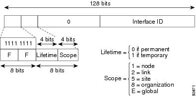
An IPv6 multicast address is an IPv6 address that has a prefix of FF00::/8 (1111 1111). An IPv6 multicast address is an identifier for a set of interfaces that typically belong to different nodes. A packet sent to a multicast address is delivered to all interfaces identified by the multicast address. The second octet following the prefix defines the lifetime and scope of the multicast address. A permanent multicast address has a lifetime parameter equal to 0; a temporary multicast address has a lifetime parameter equal to 1. A multicast address that has the scope of a node, link, site, or organization, or a global scope has a scope parameter of 1, 2, 5, 8, or E, respectively. For example, a multicast address with the prefix FF02::/16 is a permanent multicast address with a link scope. The figure below shows the format of the IPv6 multicast address.
IPv6 nodes (hosts and routers) are required to join (receive packets destined for) the following multicast groups:
- All-nodes multicast group FF02:0:0:0:0:0:0:1 (scope is link-local)
- Solicited-node multicast group FF02:0:0:0:0:1:FF00:0000/104 for each of its assigned unicast and anycast addresses
IPv6 routers must also join the all-routers multicast group FF02:0:0:0:0:0:0:2 (scope is link-local).
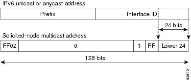
The solicited-node multicast address is a multicast group that corresponds to an IPv6 unicast or anycast address. IPv6 nodes must join the associated solicited-node multicast group for every unicast and anycast address to which it is assigned. The IPv6 solicited-node multicast address has the prefix FF02:0:0:0:0:1:FF00:0000/104 concatenated with the 24 low-order bits of a corresponding IPv6 unicast or anycast address (see the figure below). For example, the solicited-node multicast address corresponding to the IPv6 address 2037::01:800:200E:8C6C is FF02::1:FF0E:8C6C. Solicited-node addresses are used in neighbor solicitation messages.
 Note | There are no broadcast addresses in IPv6. IPv6 multicast addresses are used instead of broadcast addresses. |
IPv6 Multicast Groups
An IPv6 address must be configured on an interface before the interface can forward IPv6 traffic. Configuring a site-local or global IPv6 address on an interface automatically configures a link-local address and activates IPv6 for that interface. Additionally, the configured interface automatically joins the following required multicast groups for that link:
IPv6 Multicast Address Group Range Support
This feature provides an access control mechanism for IPv6 multicast edge routing. The ACL specifies the multicast groups or channels that are to be permitted or denied. For groups or channels that are denied, the device ignores protocol traffic and actions (for example, no MLD states are created, no mroute states are created, no PIM joins are forwarded), and drops data traffic on all interfaces in the system, disabling multicast for groups or channels denied by the ACL.
Scoped Address Architecture
IPv6 includes support for global and nonglobal addresses. This section describes the usage of IPv6 addresses of different scopes.
A scope zone, or a simply a zone, is a connected region of topology of a given scope. For example, the set of links connected by devices within a particular site, and the interfaces attached to those links, comprise a single zone of site-local scope.
A zone is a particular instance of a topological region (for example, Zone1's site or Zone2's site), whereas a scope is the size of a topological region (for example, a site or a link). The zone to which a particular nonglobal address pertains is not encoded in the address itself, but rather is determined by context, such as the interface from which it is sent or received. Therefore, addresses of a given nonglobal scope may be reused in different zones of that scope. For example, Zone1's site and Zone2's site may each contain a node with site-local address FEC0::1.
- Each link, and the interfaces attached to that link, comprises a single zone of link-local scope (for both unicast and multicast).
- There is a single zone of global scope (for both unicast and multicast), comprising all the links and interfaces in the Internet.
- The boundaries of zones of scope other than interface-local, link-local, and global must be defined and configured by network administrators. A site boundary serves as such for both unicast and multicast.
Zone boundaries are relatively static features and do not change in response to short-term changes in topology. Therefore, the requirement that the topology within a zone be "connected" is intended to include links and interfaces that may be connected only occasionally. For example, a residential node or network that obtains Internet access by dialup to an employer's site may be treated as part of the employer's site-local zone even when the dialup link is disconnected. Similarly, a failure of a device, interface, or link that causes a zone to become partitioned does not split that zone into multiple zones; rather, the different partitions are still considered to belong to the same zone.
- Zone boundaries cut through nodes, not links (the global zone has no boundary, and the boundary of an interface-local zone encloses just a single interface.)
- Zones of the same scope cannot overlap; that is, they can have no links or interfaces in common.
- A zone of a given scope (less than global) falls completely within zones of larger scope; that is, a smaller scope zone cannot include more topology than any larger scope zone with which it shares any links or interfaces.
- Each interface belongs to exactly one zone of each possible scope.
MRIB
The Multicast Routing Information Base (MRIB) is a protocol-independent repository of multicast routing entries instantiated by multicast routing protocols (routing clients). Its main function is to provide independence between routing protocols and the Multicast Forwarding Information Base (MFIB). It also acts as a coordination and communication point among its clients.
Routing clients use the services provided by the MRIB to instantiate routing entries and retrieve changes made to routing entries by other clients. Besides routing clients, MRIB also has forwarding clients (MFIB instances) and special clients such as MLD. MFIB retrieves its forwarding entries from MRIB and notifies the MRIB of any events related to packet reception. These notifications can either be explicitly requested by routing clients or spontaneously generated by the MFIB.
Another important function of the MRIB is to allow for the coordination of multiple routing clients in establishing multicast connectivity within the same multicast session. MRIB also allows for the coordination between MLD and routing protocols.
IPv6 Multicast Process Switching and Fast Switching
A unified MFIB is used to provide both fast switching and process switching support for PIM-SM and PIM-SSM in IPv6 multicast. In process switching, the Route Processor must examine, rewrite, and forward each packet. The packet is first received and copied into the system memory. The device then looks up the Layer 3 network address in the routing table. The Layer 2 frame is then rewritten with the next-hop destination address and sent to the outgoing interface. The RP also computes the cyclic redundancy check (CRC). This switching method is the least scalable method for switching IPv6 packets.
IPv6 multicast fast switching allows devices to provide better packet forwarding performance than process switching. Information conventionally stored in a route cache is stored in several data structures for IPv6 multicast switching. The data structures provide optimized lookup for efficient packet forwarding.
In IPv6 multicast forwarding, the first packet is fast-switched if the PIM protocol logic allows it. In IPv6 multicast fast switching, the MAC encapsulation header is precomputed. IPv6 multicast fast switching uses the MFIB to make IPv6 destination prefix-based switching decisions. In addition to the MFIB, IPv6 multicast fast switching uses adjacency tables to prepend Layer 2 addressing information. The adjacency table maintains Layer 2 next-hop addresses for all MFIB entries.
The adjacency table is populated as adjacencies are discovered. Each time an adjacency entry is created (such as through ARP), a link-layer header for that adjacent node is precomputed and stored in the adjacency table. Once a route is determined, it points to a next hop and corresponding adjacency entry. It is subsequently used for encapsulation during switching of packets.
A route might have several paths to a destination prefix, such as when a device is configured for simultaneous load balancing and redundancy. For each resolved path, a pointer is added for the adjacency corresponding to the next-hop interface for that path. This mechanism is used for load balancing across several paths.
IPv6 Anycast RP Solution
PIMv6 Anycast RP Solution Overview
The anycast RP solution in IPv6 PIM allows an IPv6 network to support anycast services for the PIM-SM RP. It allows anycast RP to be used inside a domain that runs PIM only. Anycast RP can be used in IPv4 as well as IPv6, but it does not depend on the Multicast Source Discovery Protocol (MSDP), which runs only on IPv4. This feature is useful when interdomain connection is not required.
Anycast RP is a mechanism that ISP-based backbones use to get fast convergence when a PIM RP device fails. To allow receivers and sources to rendezvous to the closest RP, the packets from a source need to get to all RPs to find joined receivers.
A unicast IP address is chosen as the RP address. This address is either statically configured or distributed using a dynamic protocol to all PIM devices throughout the domain. A set of devices in the domain is chosen to act as RPs for this RP address; these devices are called the anycast RP set. Each device in the anycast RP set is configured with a loopback interface using the RP address. Each device in the anycast RP set also needs a separate physical IP address to be used for communication between the RPs.
The RP address, or a prefix that covers the RP address, is injected into the unicast routing system inside of the domain. Each device in the anycast RP set is configured with the addresses of all other devices in the anycast RP set, and this configuration must be consistent in all RPs in the set.
PIMv6 Anycast RP Normal Operation
- RP1, RP2, RP3, and RP4 are members in the same anycast RP group.
- S11 and S31 are sources that use RP1 and RP3, respectively, based on their unicast routing metric.
- R11, R12, R2, R31, and R32 are receivers. Based on their unicast routing metrics, R11 and R12 join to RP1, R2 joins to RP2 and R31, and R32 joins to RP3, respectively.
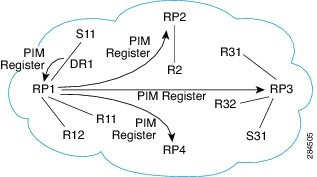
The following sequence of events occurs when S11 starts sending packets:
- DR1 creates (S,G) states and sends a register to RP1. DR1 may also encapsulate the data packet in the register.
- Upon receiving the register, RP1 performs normal PIM-SM RP functionality, and forwards the packets to R11 and R12.
- RP1 also sends the register (which may encapsulate the data packets) to RP2, RP3, and RP4.
- RP2, RP3, and RP4 do not further forward the register to each other.
- RP2, RP3, and RP4 perform normal PIM-SM RP functionality, and if there is a data packet encapsulated, RP2 forwards the data packet to R2 and RP3 forwards the data packet to R31 and R32, respectively.
- The previous five steps repeat for null registers sent by DR1.
IPv6 BSR
- IPv6 BSR
- IPv6 BSR: Configure RP Mapping
- IPv6 BSR: Scoped Zone Support
- IPv6 Multicast: RPF Flooding of BSR Packets
IPv6 BSR
PIM devices in a domain must be able to map each multicast group to the correct RP address. The BSR protocol for PIM-SM provides a dynamic, adaptive mechanism to distribute group-to-RP mapping information rapidly throughout a domain. With the IPv6 BSR feature, if an RP becomes unreachable, it will be detected and the mapping tables will be modified so that the unreachable RP is no longer used, and the new tables will be rapidly distributed throughout the domain.
Every PIM-SM multicast group needs to be associated with the IP or IPv6 address of an RP. When a new multicast sender starts sending, its local DR will encapsulate these data packets in a PIM register message and send them to the RP for that multicast group. When a new multicast receiver joins, its local DR will send a PIM join message to the RP for that multicast group. When any PIM device sends a (*, G) join message, the PIM device needs to know which is the next device toward the RP so that G (Group) can send a message to that device. Also, when a PIM device is forwarding data packets using (*, G) state, the PIM device needs to know which is the correct incoming interface for packets destined for G, because it needs to reject any packets that arrive on other interfaces.
A small set of devices from a domain are configured as candidate bootstrap routers (C-BSRs) and a single BSR is selected for that domain. A set of devices within a domain are also configured as candidate RPs (C-RPs); typically, these devices are the same devices that are configured as C-BSRs. Candidate RPs periodically unicast candidate-RP-advertisement (C-RP-Adv) messages to the BSR of that domain, advertising their willingness to be an RP. A C-RP-Adv message includes the address of the advertising C-RP, and an optional list of group addresses and mask length fields, indicating the group prefixes for which the candidacy is advertised. The BSR then includes a set of these C-RPs, along with their corresponding group prefixes, in bootstrap messages (BSMs) it periodically originates. BSMs are distributed hop-by-hop throughout the domain.
Bidirectional BSR support allows bidirectional RPs to be advertised in C-RP messages and bidirectional ranges in the BSM. All devices in a system must be able to use the bidirectional range in the BSM; otherwise, the bidirectional RP feature will not function.
IPv6 BSR: Configure RP Mapping
The IPv6 BSR ability to configure RP mapping allows IPv6 multicast devices to be statically configured to announce scope-to-RP mappings directly from the BSR instead of learning them from candidate-RP messages. Announcing RP mappings from the BSR is useful in several situations:
- When an RP address never changes because there is only a single RP or the group range uses an anycast RP, it may be less complex to configure the RP address announcement statically on the candidate BSRs.
- When an RP address is a virtual RP address (such as when using bidirectional PIM), it cannot be learned by the BSR from a candidate-RP. Instead, the virtual RP address must be configured as an announced RP on the candidate BSRs.
IPv6 BSR: Scoped Zone Support
BSR provides scoped zone support by distributing group-to-RP mappings in networks using administratively scoped multicast. The user can configure candidate BSRs and a set of candidate RPs for each administratively scoped region in the user's domain.
For BSR to function correctly with administrative scoping, a BSR and at least one C-RP must be within every administratively scoped region. Administratively scoped zone boundaries must be configured at the zone border devices, because they need to filter PIM join messages that might inadvertently cross the border due to error conditions. In addition, at least one C-BSR within the administratively scoped zone must be configured to be a C-BSR for the administratively scoped zone's address range.
A separate BSR election will then take place (using BSMs) for every administratively scoped range, plus one for the global range. Administratively scoped ranges are identified in the BSM because the group range is marked to indicate that this is an administrative scope range, not just a range that a particular set of RPs is configured to handle.
Unless the C-RP is configured with a scope, it discovers the existence of the administratively scoped zone and its group range through reception of a BSM from the scope zone's elected BSR containing the scope zone's group range. A C-RP stores each elected BSR's address and the administratively scoped range contained in its BSM. It separately unicasts C-RP-Adv messages to the appropriate BSR for every administratively scoped range within which it is willing to serve as an RP.
All PIM devices within a PIM bootstrap domain where administratively scoped ranges are in use must be able to receive BSMs and store the winning BSR and RP set for all administratively scoped zones that apply.
IPv6 Multicast: RPF Flooding of BSR Packets
Cisco IPv6 devices provide support for the RPF flooding of BSR packets so that the device will not disrupt the flow of BSMs. The device will recognize and parse enough of the BSM to identify the BSR address. The device performs an RPF check for this BSR address and forwards the packet only if it is received on the RPF interface. The device also creates a BSR entry containing RPF information to use for future BSMs from the same BSR. When BSMs from a given BSR are no longer received, the BSR entry is timed out.
IPv6 Multicast Groups
An IPv6 address must be configured on an interface before the interface can forward IPv6 traffic. Configuring a site-local or global IPv6 address on an interface automatically configures a link-local address and activates IPv6 for that interface. Additionally, the configured interface automatically joins the following required multicast groups for that link:
IPv6 Multicast Address Group Range Support
This feature provides an access control mechanism for IPv6 multicast edge routing. The ACL specifies the multicast groups or channels that are to be permitted or denied. For groups or channels that are denied, the device ignores protocol traffic and actions (for example, no MLD states are created, no mroute states are created, no PIM joins are forwarded), and drops data traffic on all interfaces in the system, disabling multicast for groups or channels denied by the ACL.
How to Configure Basic IP Multicast in IPv6 Networks
- Enabling IPv6 Multicast Routing
- Disabling the Device from Receiving Unauthenticated Multicast Traffic
- Troubleshooting IPv6 Multicast
- Configuring PIMv6 Anycast RP
- Configuring a BSR and Verifying BSR Information
- Sending PIM RP Advertisements to the BSR
- Configuring BSR for Use Within Scoped Zones
- Configuring BSR Devices to Announce Scope-to-RP Mappings
Enabling IPv6 Multicast Routing
IPv6 multicast uses MLD version 2. This version of MLD is fully backward-compatible with MLD version 1 (described in RFC 2710). Hosts that support only MLD version 1 will interoperate with a device running MLD version 2. Mixed LANs with both MLD version 1 and MLD version 2 hosts are likewise supported.
You must first enable IPv6 unicast routing on all interfaces of the device on which you want to enable IPv6 multicast routing .
DETAILED STEPS
Disabling the Device from Receiving Unauthenticated Multicast Traffic
In some situations, access control may be needed to prevent multicast traffic from being received unless the subscriber is authenticated and the channels are authorized as per access control profiles. That is, there should be no traffic at all unless specified otherwise by access control profiles.
Perform this task to disable the device from receiving multicast traffic to be received from unauthenticated groups or unauthorized channels.
DETAILED STEPS
Troubleshooting IPv6 Multicast
DETAILED STEPS
Configuring PIMv6 Anycast RP
This task describes how to configure two PIMv6 anycast RP peers. Steps 3 through 11 show the configuration for RP1, and Steps 12 through 19 show the configuration for RP2.
DETAILED STEPS
Configuring a BSR and Verifying BSR Information
DETAILED STEPS
Sending PIM RP Advertisements to the BSR
DETAILED STEPS
Configuring BSR for Use Within Scoped Zones
A user can configure candidate BSRs and a set of candidate RPs for each administratively scoped region in the domain.
If scope is specified on the candidate RP, then this device will advertise itself as C-RP only to the BSR for the specified scope. If the group list is specified along with the scope, then only prefixes in the access list with the same scope as that configured will be advertised.
If a scope is specified on the bootstrap device, the BSR will originate BSMs including the group range associated with the scope and accept C-RP announcements for groups that belong to the given scope.
DETAILED STEPS
Configuring BSR Devices to Announce Scope-to-RP Mappings
IPv6 BSR devices can be statically configured to announce scope-to-RP mappings directly instead of learning them from candidate-RP messages. A user might want to configure a BSR device to announce scope-to-RP mappings so that an RP that does not support BSR is imported into the BSR. Enabling this feature also allows an RP positioned outside the enterprise's BSR domain to be learned by the known remote RP on the local candidate BSR devices.
DETAILED STEPS
Configuration Examples for Configuring IP Multicast Basic in IPv6 Networks
- Example: Enabling IPv6 Multicast Routing
- Examples: Disabling IPv6 Multicast Address Group Range Support
- Example: Verifying IPv6 MRIB Information
- Example: Configuring PIMv6 Anycast RP
- Example: Configuring a BSR
Examples: Disabling IPv6 Multicast Address Group Range Support
The following example ensures that the device disables multicast for groups or channels denied by an access list named list2:
ipv6 multicast group-range list2
The following example shows that the command in the previous example is overridden on an interface specified by int2. On int2, MLD states are created for groups or channels permitted by int-list2 but are not created for groups or channels denied by int-list2. On all other interfaces, the access-list named list2 is used for access control.
In this example, list2 can be specified to deny all or most multicast groups or channels, and int-list2 can be specified to permit authorized groups or channels only for interface int2.
Device(config)# interface int2
Device(config-if)# ipv6 mld access-group int-list2
Example: Verifying IPv6 MRIB Information
The following example displays information about the IPv6 MRIB client:
Device# show ipv6 mrib client

IP MRIB client-connections
igmp:145        (connection id 0)
pim:146 (connection id 1)
mfib ipv6:3     (connection id 2)
slot 3  mfib ipv6 rp agent:16   (connection id 3)
slot 1  mfib ipv6 rp agent:16   (connection id 4)
slot 0  mfib ipv6 rp agent:16   (connection id 5)
slot 4  mfib ipv6 rp agent:16   (connection id 6)
slot 2  mfib ipv6 rp agent:16   (connection id 7)
The following example displays summary information about the IPv6 MRIB route:
Device# show ipv6 mrib route summary

MRIB Route-DB Summary
  No. of (*,G) routes = 52
  No. of (S,G) routes = 0
  No. of Route x Interfaces (RxI) = 10
Example: Configuring PIMv6 Anycast RP
RP1
Device1(config)# ipv6 pim rp-address 2001:DB8::1:1 acl_sparse1
Device1(config)# interface Loopback4
Device1(config-if)# ipv6 address 2001:DB8::4:4/64
Device1(config-if)# no shut

Device1(config)# interface Loopback5
Device1(config-if)# ipv6 address 2001:DB8:0:ABCD::1/64
Device1(config-if)# no shut
Device1(config-if)# exit
Device1(config)# ipv6 pim anycast-rp 2001:DB8:0:ABCD::1 2001:DB8::3:3

RP2 (Anycast RP Peer)
Device2(config)# ipv6 pim rp-address 2001:DB8::1:1 acl_sparse1
Device2(config)# interface Loopback4
Device2(config-if)# ipv6 address 2001:DB8::3:3/64
Device2(config-if)# no shut

Device2(config)# interface Loopback5
Device2(config-if)# ipv6 address 2001:DB8:0:ABCD::1/64
Device2(config-if)# no shut
Device2(config)# ipv6 pim anycast-rp 2001:DB8::1:1 2001:DB8::4:4
Example: Configuring a BSR
Device# show ipv6 pim bsr election

PIMv2 BSR information
BSR Election Information
Scope Range List: ff00::/8
This system is the Bootstrap Router (BSR)
BSR Address: 60::1:1:4
Uptime: 00:11:55, BSR Priority: 0, Hash mask length: 126
RPF: FE80::A8BB:CCFF:FE03:C400,Ethernet0/0
BS Timer: 00:00:07
This system is candidate BSR
Candidate BSR address: 60::1:1:4, priority: 0, hash mask length: 126
Additional References
Related Documents
MIBs
Technical Assistance
| Description | Link |
|---|---|
|
The Cisco Support and Documentation website provides online resources to download documentation, software, and tools. Use these resources to install and configure the software and to troubleshoot and resolve technical issues with Cisco products and technologies. Access to most tools on the Cisco Support and Documentation website requires a Cisco.com user ID and password. |
Feature Information for Configuring Basic IP Multicast in IPv6 Networks
The following table provides release information about the feature or features described in this module. This table lists only the software release that introduced support for a given feature in a given software release train. Unless noted otherwise, subsequent releases of that software release train also support that feature.
Use Cisco Feature Navigator to find information about platform support and Cisco software image support. To access Cisco Feature Navigator, go to www.cisco.com/go/cfn. An account on Cisco.com is not required.
| Table 1 | Feature Information for Configuring Basic IP Multicast in IPv6 Networks |
| Feature Name | Releases | Feature Information |
|---|---|---|
|
IPv6 Multicast |
12.0(26)S 12.2(25)SG 12.2(33)SRA 12.2(18)SXE 12.3(2)T 12.4 12.4(2)T Cisco IOS XE Release 2.1 |
IPv6 multicast allows a host to send a single data stream to a subset of all hosts simultaneously. The following commands were introduced or modified: clear ipv6 pim topology, debug ipv6 mld, debug ipv6 mrib, debug ipv6 pim, debug ipv6 pim neighbor, ipv6 mld join-group, ipv6 mld static-group, ipv6 mld query-interval, ipv6 mld query-max-response-time, ipv6 mld query-timeout, ipv6 mld router, ipv6 multicast-routing , ipv6 pim, ipv6 pim dr-priority, ipv6 pim hello-interval, ipv6 pim rp-address , ipv6 pim spt-threshold infinity , show ipv6 mld groups, show ipv6 mld groups summary, show ipv6 mld interface, show ipv6 mrib client, show ipv6 mrib route, show ipv6 mroute, show ipv6 pim group-map, show ipv6 pim interface, show ipv6 pim neighbor, show ipv6 pim range-list, show ipv6 pim topology, show ipv6 pim tunnel. |
|
IPv6 Multicast Address Group Range Support |
15.0(1)M 12.2(40)SG 3.2.0SG 15.0(2)SG 12.2(33)SRE 12.2(33)SXI Cisco IOS XE Release 2.6 |
This feature is also known as Disable Group Ranges. This feature provides an access control mechanism for IPv6 multicast edge routing. The following commands were introduced or modified: ipv6 mld access-group, ipv6 multicast boundary scope, ipv6 multicast group-range. |
|
IPv6 Multicast: Scope Boundaries |
12.0(26)S 12.2(18)S 12.2(25)SG 12.2(33)SRA 12.3(2)T 12.4 12.4(2)T 15.0(1)S |
IPv6 includes support for global and nonglobal addresses. This feature describes the usage of IPv6 addresses of different scopes. |
|
PIMv6: Anycast RP Solution |
15.1(3)S Cisco IOS XE Release 3.4S 15.2(3)T |
The anycast RP solution in IPv6 PIM enables an IPv6 network to support anycast services for the PIM-SM RP and allows anycast RP to be used inside a domain that runs PIM only. The following commands were introduced or modified: ipv6 pim anycast-RP, show ipv6 pim anycast-RP. |
|
IPv6 Multicast: Bootstrap Router |
12.0(28)S 12.2(25)S 12.2(25)SG 12.2(33)SRA 12.2(33)SXH 12.3(11)T 12.4 12.4(2)T Cisco IOS XE Release 2.4 15.0(1)S |
If an RP becomes unreachable, this feature allows the RP to be detected and the mapping tables modified so that the unreachable RP is no longer used, and the new tables will be rapidly distributed throughout the domain. The following commands were introduced or modified: debug ipv6 pim bsr, ipv6 pim bsr border, ipv6 pim bsr candidate bsr, ipv6 pim bsr candidate rp, show ipv6 pim bsr, show ipv6 pim group-map. |
|
IPv6 BSR Bi-Dir Support |
12.2(33)SRE 12.3(14)T 15.0(1)S |
Bidirectional BSR support allows bidirectional RPs to be advertised in C-RP messages and bidirectional ranges in the BSM. |
|
IPv6 BSR: Configure RP Mapping |
12.2(33)SRE 12.2(50)SY 12.4(2)T Cisco IOS XE Release 2.4 15.0(1)S |
This feature allows IPv6 multicast devices to be statically configured to announce scope-to-RP mappings directly from the BSR instead of learning them from candidate-RP messages. The following commands were introduced or modified: ipv6 multicast-routing, ipv6 pim bsr announced rp, ipv6 pim bsr candidate bsr. |
|
IPv6 Multicast: RPF Flooding of BSR Packets |
12.0(26)S 12.3(4)T 12.2(25)S 12.2(25)SG 12.2(33)SRA 12.2(33)SXH 12.4 12.4(2)T 15.0(1)S |
The RPF flooding of BSR packets feature enables a Cisco IPv6 device to not disrupt the flow of BSMs. The following command was introduced: show ipv6 pim bsr. |
|
IPv6 BSR Scoped Zone Support |
12.2(18)SXE |
BSR provides scoped zone support by distributing group-to-RP mappings in networks using administratively scoped multicast. The user can configure candidate BSRs and a set of candidate RPs for each administratively scoped region in the user's domain. The following commands were introduced or modified: ipv6 multicast boundary scope, ipv6 pim bsr candidate bsr, ipv6 pim bsr candidate rp. |
| IPv6 Multicast VRF Lite |
15.1(4)M Cisco IOS XE Release 3.4S |
This feature provides IPv6 multicast support for multiple virtual routing/forwarding contexts (VRFs), the scope of which is limited to the device in which the VRFs are defined. |
Cisco and the Cisco logo are trademarks or registered trademarks of Cisco and/or its affiliates in the U.S. and other countries. To view a list of Cisco trademarks, go to this URL: www.cisco.com/go/trademarks. Third-party trademarks mentioned are the property of their respective owners. The use of the word partner does not imply a partnership relationship between Cisco and any other company. (1110R)
Any Internet Protocol (IP) addresses and phone numbers used in this document are not intended to be actual addresses and phone numbers. Any examples, command display output, network topology diagrams, and other figures included in the document are shown for illustrative purposes only. Any use of actual IP addresses or phone numbers in illustrative content is unintentional and coincidental.