
 Feedback
Contents
- MLDP-Based MVPN
- Finding Feature Information
- Prerequisites for MLDP-Based MVPN
- Information About MLDP-Based MVPN
- Overview of MLDP-Based MVPN
- Benefits of MLDP-Based MVPN
- Initial Deployment of an MLDP-Based MVPN
- Default MDT Creation
- LSP Downstream Default MDT Creation
- LSP Upstream Default MDT Creation
- PIM Overlay Signaling of VPN Multicast State
- Data MDT Creation
- Data MDT Scenario
- How to Configure MLDP-Based MVPN
- Configuring Initial MLDP Settings
- Configuring an MLDP-Based MVPN
- Verifying the Configuration of an MLDP-Based MVPN
- Configuration Examples for MLDP-Based MVPN
- Example Initial Deployment of an MLDP-Based MVPN
- Default MDT Configuration
- PIM Adjacencies
- MLDP Database Entry--PE-East
- Label Forwarding Entry--P-Central (Root 1)
- Data MDT Configuration
- VRF mroute Table--PE-West
- LSP-VIF Adjacencies--PE-West
- MLDP Database Entries
- LFIB Entry for the Data MDT
- Example Migration from a PIM with mGRE-Based MVPN to an MLDP-Based MPVN
- Additional References
- Feature Information for MLDP-Based MVPN
MLDP-Based MVPN
The MLDP-based MVPN feature provides extensions to Label Distribution Protocol (LDP) for the setup of point-to-multipoint (P2MP) and multipoint-to-multipoint (MP2MP) label switched paths (LSPs) for transport in the Multicast Virtual Private Network (MVPN) core network.
Finding Feature Information
Your software release may not support all the features documented in this module. For the latest feature information and caveats, see the release notes for your platform and software release. To find information about the features documented in this module, and to see a list of the releases in which each feature is supported, see the Feature Information Table at the end of this document.
Use Cisco Feature Navigator to find information about platform support and Cisco software image support. To access Cisco Feature Navigator, go to www.cisco.com/go/cfn. An account on Cisco.com is not required.
Prerequisites for MLDP-Based MVPN
- You are familiar with IP multicast concepts and configuration tasks.
- You are familiar with MVPN concepts and configuration tasks.
- You are familiar with Multiprotocol Label Switching (MPLS) Layer 3 VPN concepts and configuration tasks.
Information About MLDP-Based MVPN
Overview of MLDP-Based MVPN
MVPN allows a service provider to configure and support multicast traffic in an MPLS VPN environment. This feature supports routing and forwarding of multicast packets for each individual VPN routing and forwarding (VRF) instance, and it also provides a mechanism to transport VPN multicast packets across the service provider backbone.
A VPN is network connectivity across a shared infrastructure, such as an Internet service provider (ISP). Its function is to provide the same policies and performance as a private network, at a reduced cost of ownership, thus creating many opportunities for cost savings through operations and infrastructure.
An MVPN allows an enterprise to transparently interconnect its private network across the network backbone of a service provider. The use of an MVPN to interconnect an enterprise network in this way does not change the way that the enterprise network is administered, nor does it change general enterprise connectivity.
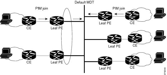
As shown in the figure, in an MLDP-based MVPN, a static default multicast distribution tree (MDT) is established for each multicast domain. The default MDT defines the path used by provider edge (PE) routers to send multicast data and control messages to every other PE router in the multicast domain. A default MDT is created in the core network using a single MP2MP LSP. The default MDT behaves like a virtual LAN.
As shown in the figure, an MLDP-based MVPN also supports the dynamic creation of data MDTs for high-bandwidth transmission. For high-rate data sources, a data MDT is created using P2MP LSPs to off-load traffic from the default MDT to avoid unnecessary waste of bandwidth to PEs that did not join the stream. The creation of the data MDT is signaled dynamically using MDT Join TLV messages. Data MDTs are a feature unique to Cisco IOS software. Data MDTs are intended for high-bandwidth sources such as full-motion video inside the VPN to ensure optimal traffic forwarding in the MPLS VPN core. The threshold at which the data MDT is created can be configured on a per-router or a per-VRF basis. When the multicast transmission exceeds the defined threshold, the sending PE router creates the data MDT and sends a User Datagram Protocol (UDP) message, which contains information about the data MDT to all routers on the default MDT.
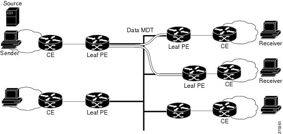
Data MDTs are created only for (S, G) multicast route entries within the VRF multicast routing table. They are not created for (*, G) entries regardless of the value of the individual source data rate.
The only transport mechanism previously available was Protocol Independent Multicast (PIM) with Multipoint Generic Routing Encapsulation (mGRE) over an IP core network. The introduction of Multicast Label Distribution Protocol (MLDP) provides transport by using MLDP with label encapsulation over an MPLS core network.
MLDP creates the MDTs as follows:
All other operations of MVPN remain the same regardless of the tunneling mechanism:
- PIM neighbors in a VRF are seen across a Label Switched Path virtual interface (LSP-VIF).
- The VPN multicast state is signaled by PIM.
The only other difference when using MLDP is that the MDT group address used in the mGRE solution is replaced with a VPN ID.
Benefits of MLDP-Based MVPN
- Enables the use of a single MPLS forwarding plane for both unicast and multicast traffic.
- Enables existing MPLS protection (for example, MPLS Traffic Engineering/Resource Reservation Protocol (TE/RSVP link protection) and MPLS Operations Administration and Maintenance (OAM) mechanisms to be used for multicast traffic.
- Reduces operational complexity due to the elimination of the need for PIM in the MPLS core network.
Initial Deployment of an MLDP-Based MVPN
Initial deployment of an MLDP-based MVPN involves the configuration of a default MDT and one or more data MDTs.
A static default MDT is established for each multicast domain. The default MDT defines the path used by PE routers to send multicast data and control messages to every other PE router in the multicast domain. A default MDT is created in the core network using a single MP2MP LSP.
An MLDP-based MVPN also supports the dynamic creation of data MDTs for high-bandwidth transmission.
Default MDT Creation
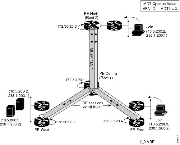
The figure shows the default MDT scenario. The Opaque value used to signal a default MDT consists of two parameters: the VPN ID and the MDT number for the VPN in the format (vpn-id, 0) where vpn-id is a manually configured 7-byte number that uniquely identifies this VPN. The default MDT is set to zero.
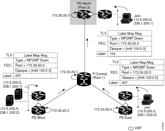
In this scenario, each of the three PE routers belong to the VRF called VRF and they have the same VPN ID. Each PE router with the same VPN ID will join the same MP2MP tree. The PE routers have created a primary MP2MP tree rooted at P-Central (Root 1) and a backup MP2MP tree rooted at PE-North (Root 2). There are two sources at PE-West and interested receivers at both PE-North and PE-East. PE-West will choose one of the MP2MP trees to transmit the customer VPN traffic, but all PE routers can receive traffic on either of the MP2MP trees.
- LSP Downstream Default MDT Creation
- LSP Upstream Default MDT Creation
- PIM Overlay Signaling of VPN Multicast State
LSP Downstream Default MDT Creation
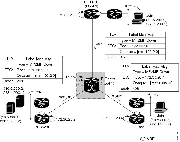
The figures show the downstream tree creation for each of the roots. Each PE router configured with VPN ID 100:2 creates the same Forwarding Equivalence Class (FEC) Type Length Value (TLV), but with a different root and downstream labels per MP2MP tree. The FEC type will be MP2MP Down, which prompts the receiving Label Switched Route (LSR) to respond with an upstream label mapping message to create the upstream path.
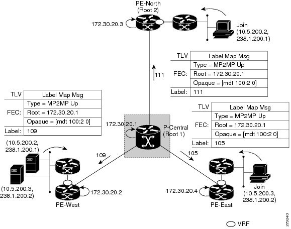
LSP Upstream Default MDT Creation
The figures show the upstream LSP creation for the default MDTs. For each downstream label received, a corresponding upstream label is sent. In the first figure, P-Central sends out three upstream labels (111, 109, and 105) to each downstream directly connected neighbor (downstream is away from the root). The process for PE-North is the same except that it only sends a single upstream label (313) as there is only one directly connected downstream neighbor, as shown in the second figure.

PIM Overlay Signaling of VPN Multicast State
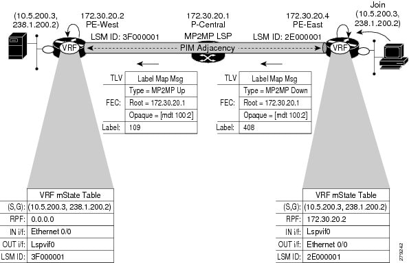
The signaling of the multicast state within a VPN is via PIM. It is called overlay signaling because the PIM session runs over the multipoint LSP and maps the VPN multicast flow to the LSP. In an MVPN, the operation of PIM is independent of the underlying tunnel technology. In the MVPN solution, a PIM adjacency is created between PE routers, and the multicast states within a VRF are populated over the PIM sessions. When using MLDP, the PIM session runs over an LSP-VIF interface. The figure shows PIM signaling running over the default MDT MP2MP LSP. Access to the MP2MP LSP is via the LSP-VIF, which can see all the leaf PE routers at the end of branches, much like a LAN interface. In the figure, PE-East sends a downstream label mapping message to the root, P-Central, which in turn sends an upstream label mapping message to PE-West. These messages result in the creation of the LSP between the two leaf PE routers. A PIM session can then be activated over the top of the LSP allowing the (S, G) states and control messages to be signaled between PE-West and PE-East. In this case, PE-East receives a Join TLV message for (10.5.200.3, 238.1.200.2) within VRF, which it inserts into the mroute table. The Join TLV message is then sent via the PIM session to PE-West (BGP next-hop of 10.5.200.3), which populates its VRF mroute table. This procedure is identical to the procedure using an mGRE tunnel.
Data MDT Creation
In an MVPN, traffic that exceeds a certain threshold can move off the default MDT onto a data MDT. This section discusses how a data MDT is created using MLDP.
Data MDT Scenario
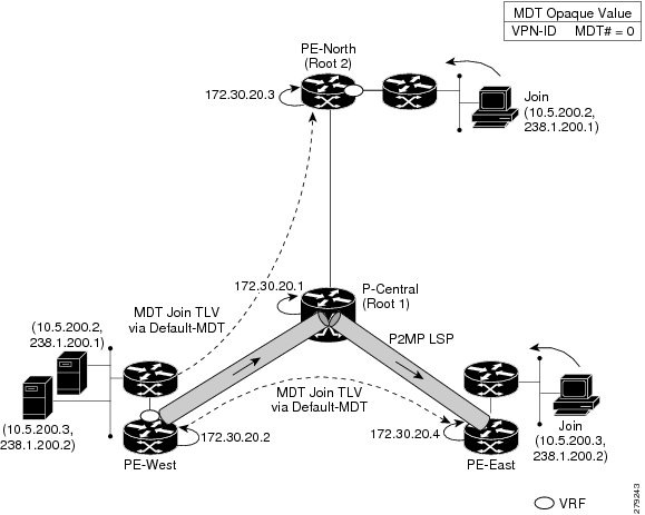
The figure shows the data MDT scenario. The Opaque value used to signal a data MDT consists of two parameters: the VPN ID and the MDT number in the format (vpn-id, MDT# > 0) where vpn-id is a manually configured 7-byte number that uniquely identifies this VPN. The second parameter is the unique data MDT number for this VPN, which is a number greater than zero.
In the scenario, two receivers at PE-North and PE-East are interested in two sources at PE-West. If the source 10.5.200.3 exceeds the threshold on the default MDT, PE-West will issue an MDT Join TLV message over the default MDT MP2MP LSP advising all PE routers that a new data MDT is being created.
Because PE-East has an interested receiver in VRF, it will build a multipoint LSP using P2MP back to PE-West, which will be the root of the tree. PE-North does not have a receiver for 10.5.200.3, therefore it will just cache the Join TLV message.
How to Configure MLDP-Based MVPN
- Configuring Initial MLDP Settings
- Configuring an MLDP-Based MVPN
- Verifying the Configuration of an MLDP-Based MVPN
Configuring Initial MLDP Settings
DETAILED STEPS
Configuring an MLDP-Based MVPN
DETAILED STEPS
Verifying the Configuration of an MLDP-Based MVPN
DETAILED STEPS
| Step 1 |
show mpls mldp database
Enter the show mpls mldp databasecommand to display information in the MLDP database. It shows the FEC, the Opaque value of the FEC decoded, and the replication clients associated with it: Example: Router# show mpls mldp database * Indicates MLDP recursive forwarding is enabled LSM ID : D3000001 (RNR LSM ID: 8A000002) Type: MP2MP Uptime : 00:04:54 FEC Root : 172.30.20.1 Opaque decoded : [mdt 100:2 0] Opaque length : 11 bytes Opaque value : 07 000B 0000010000000100000000 RNR active LSP : (this entry) Upstream client(s) : 172.30.20.1:0 [Active] Expires : Never Path Set ID : 99000001 Out Label (U) : 32 Interface : Ethernet1/0* Local Label (D): 30 Next Hop : 10.0.1.7 Replication client(s): MDT (VRF VRF) Uptime : 00:04:54 Path Set ID : 5000002 Interface : Lspvif0 |
| Step 2 |
show
ip
pim
neighbor
[vrf vrf-name] neighbor [interface-type interface-number] Enter the show ip pim neighborcommand to display PIM adjacencies information: Example: Router# show ip pim vrf VRF neighbor 192.168.10.18 Serial6/0 04:53:19/00:01:18 v2 1 / G 172.30.20.3 Lspvif0 04:52:32/00:01:28 v2 1 / B S P G 172.30.20.2 Lspvif0 04:52:32/00:01:17 v2 1 / B S P G |
| Step 3 |
show
ip
mroute
[vrf vrf-name] [[active [kbps] [interface type number] | bidirectional | count [terse] | dense | interface type number | proxy | pruned | sparse | ssm | static | summary] | [group-address [source-address]] [count [terse] | interface type number | proxy | pruned | summary] | [source-address group-address] [count [terse] | interface type number | proxy | pruned | summary] | [group-address] active [kbps] [interface type number | verbose]] Enter the show ip mroutecommand to display the contents of the multicast routing (mroute) table: Example: Router# show ip mroute vrf VRF 238.1.200.2 10.5.200.3 (10.5.200.3, 238.1.200.2), 04:54:18/00:02:40, flags: sT Incoming interface: Lspvif0, RPF nbr 172.30.20.2 Outgoing interface list: Serial6/0, Forward/Sparse-Dense, 04:54:18/00:02:40 |
| Step 4 |
show
mpls
forwarding-table
[network {mask | length} | labels label [- label] | interface interface | next-hop address | lsp-tunnel [tunnel-id]] [vrf vrf-name] [detail] Enter the show mpls forwarding-tablecommand to display the contents of the MPLS Label Forwarding Information Base (LFIB): Example: Router# show mpls forwarding-table | inc 1F000001 105 307 mLDP:1F000001 38468 Se5/0 point2point 208 mLDP:1F000001 38468 Se4/0 point2point 109 307 mLDP:1F000001 34738 Se5/0 point2point 408 mLDP:1F000001 34738 Se6/0 point2point 111 408 mLDP:1F000001 282 Se6/0 point2point 208 mLDP:1F000001 282 Se4/0 point2point |
| Step 5 |
show
adjacency
[ip-address] [interface-type interface-number | null number | port-channel number | sysclock number | vlan number | ipv6-address | fcpa number | serial number] [connectionid number] [link {ipv4 | ipv6 | mpls}] [detail | encapsulation] Enter the show adjacencycommand to display adjacency information for the specified LSP-VIF interface: Example: Router# show adjacency lspvif0 105 307 mLDP:1F000001 38468 Se5/0 point2point 208 mLDP:1F000001 38468 Se4/0 point2point 109 307 mLDP:1F000001 34738 Se5/0 point2point 408 mLDP:1F000001 34738 Se6/0 point2point 111 408 mLDP:1F000001 282 Se6/0 point2point 208 mLDP:1F000001 282 Se4/0 point2point |
Configuration Examples for MLDP-Based MVPN
- Example Initial Deployment of an MLDP-Based MVPN
- Example Migration from a PIM with mGRE-Based MVPN to an MLDP-Based MPVN
Example Initial Deployment of an MLDP-Based MVPN
Default MDT Configuration
The following example shows how to configure the default MDT for an MLDP-based MVPN. This configuration is based on the sample topology illustrated in the figure.
This configuration is consistent for every PE router participating in the same VPN ID. The vpn id 100:2 command replaces the MDT group address used with the mGRE transport method. To provide redundancy, two default MDT trees are statically configured, rooted at P-Central and PE-North. The selection as to which MP2MP tree the default MDT will use at a particular PE router is determined by Interior Gateway Protocol (IGP) metrics. An MP2MP LSP is implicit for the default MDT.
ip pim mpls source Loopback0
ip multicast-routing
ip multicast-routing vrf VRF
!
ip vrf VRF
 rd 100:2
 vpn id 100:2
 route-target export 200:2
 route-target import 200:2
 mdt default mpls mldp 172.30.20.1 (P-Central)
 mdt default mpls mldp 172.30.20.3 (PE-North)
PIM Adjacencies
PIM operates over the LSP-VIF as if it were a regular tunnel interface. That means PIM hellos are exchanged over the LSP-VIF to establish PIM adjacencies over the default MDT. The sample output in this section displays the three PIM adjacencies in VRF of PE-East. The first is the adjacency to the receiver network over serial interface 6/0, and the next two are the adjacencies to PE-West and PE-North over the MP2MP LSP via LSP-VIF interface 0.
PE-East# show ip pim vrf VRF neighbor
192.168.10.18     Serial6/0            04:53:19/00:01:18 v2 1 / G
172.30.20.3       Lspvif0              04:52:32/00:01:28 v2 1 / B S P G
172.30.20.2       Lspvif0              04:52:32/00:01:17 v2 1 / B S P G
The output from the show ip mroute command also shows the (S, G) entry for VRF. The stream 238.1.200.2 has the Reverse Path Forwarding (RPF) interface of LSP-VIF interface 0 and the neighbor 172.30.20.2, which is PE-West.
PE-East# show ip mroute vrf VRF 238.1.200.2 10.5.200.3
(10.5.200.3, 238.1.200.2), 04:54:18/00:02:40, flags: sT
Incoming interface: Lspvif0, RPF nbr 172.30.20.2
Outgoing interface list:
Serial6/0, Forward/Sparse-Dense, 04:54:18/00:02:40
MLDP Database Entry--PE-East
The sample output in this section displays the database entries for the MP2MP trees supporting the default MDT at PE-East. The database is searched by Opaque value MDT 100:2, which results in information for two MP2MP trees (one for each root) being returned. Both trees have different system IDs (2E000001, F2000005) and use the same Opaque value ([mdt 100:2 0]), but with different roots. The last 0 in the Opaque value indicates this tree is a default MDT. Entry 79000004 shows it is the primary MP2MP tree, therefore PE-East will transmit all source multicast traffic on this LSP, and B2000006 will be the backup root. Note that interface LSP-VIF interface 0 represents both MP2MP LSPs. The Local Label (D) is the downstream label allocated by PE-East for this tree. In other words, traffic from the root will be received with either label 408 (Primary Tree) or 407 (Backup Tree). The Out Label (U) is the label that PE-East will use to send traffic into the tree; upstream towards the root, either 105 for the Primary Tree or 108 for the Backup Tree. Both these labels were received from P-Central.
PE-East# show mpls mldp database opaque_type mdt 100:2
* Indicates MLDP recursive forwarding is enabled
LSM ID : 79000004 (RNR LSM ID: 8A000002)   Type: MP2MP   Uptime : 00:04:54
  FEC Root           : 172.30.20.1
  Opaque decoded     : [mdt 100:2 0]
  Opaque length      : 11 bytes
  Opaque value       : 07 000B 0000010000000100000000
  RNR active LSP     : (this entry)
  Upstream client(s) :
    172.30.20.1:0    [Active]
      Expires        : Never         Path Set ID  : 99000001
      Out Label (U)  : 32            Interface    : Ethernet1/0*
      Local Label (D): 30            Next Hop     : 10.0.1.7
  Replication client(s):
    MDT  (VRF VRF)
      Uptime         : 00:04:54      Path Set ID  : 5000002
      Interface      : Lspvif0
LSM ID : 79000005 (RNR LSM ID: 8A000003)   Type: MP2MP   Uptime : 00:04:54
  FEC Root           : 172.30.20.3
  Opaque decoded     : [mdt 100:2 0]
  Opaque length      : 11 bytes
  Opaque value       : 07 000B 0000010000000100000001
  RNR active LSP     : (this entry)
  Upstream client(s) :
    172.30.20.1:0    [Active]
      Expires        : Never         Path Set ID  : 99000002
      Out Label (U)  : 32            Interface    : Ethernet1/0*
      Local Label (D): 30            Next Hop     : 10.0.1.7
  Replication client(s):
    MDT  (VRF VRF)
      Uptime         : 00:04:54      Path Set ID  : 5000003
      Interface      : Lspvif0
Label Forwarding Entry--P-Central (Root 1)
The sample output shown in this section displays the VRF (MDT 100:2) MLDP database entry 1F000001 for the primary MP2MP LSP, which is P-Central. Because the local router P-Central is the root, there is no upstream peer ID, therefore no labels are allocated locally. However there are three replication clients, representing each of the three PE routers: PE-North, PE-West, and PE-East. These replication clients are the downstream nodes of the MP2MP LSP. These clients receive multipoint replicated traffic.
In the replication entry looking from the perspective of the root, there are two types of labels:
- Out label (D)--These are labels received from remote peers that are downstream to the root (remember traffic flows downstream away from the root).
- Local label (U)--These are labels provided by P-Central to its neighbors to be used as upstream labels (sending traffic to the root). It is easy to identify these labels as they all start in the 100 range, which we have configured for P-Central to use. P-Central sends these labels out when it receives a FEC with the type as MP2MP Down.
From the labels received and sent in the replication entries, the Label Forwarding Information Base (LFIB) is created. The LFIB has one entry per upstream path and one entry per downstream path. In this case because P-Central is the root, there are only upstream entries in the LFIB that have been merged with the corresponding downstream labels. For example, label 105 is the label P-Central sent to PE-East to send source traffic upstream. Traffic received from PE-East will then be replicated using the downstream labels 307 to PE-West and 208 to PE-North.
P-Central# show mpls mldp database opaque_type mdt 100:2
LSM ID : 79000006 (RNR LSM ID: 1F000001)   Type: MP2MP   Uptime : 00:04:54
  FEC Root           : 172.30.20.1
  Opaque decoded     : [mdt 100:2 0]
  Opaque length      : 11 bytes
  Opaque value       : 07 000B 0000010000000100000000
  RNR active LSP     : (this entry)
  Upstream client(s) : None
  Replication client(s):
    172.3.20.2:0
      Uptime         : 01:46:43      Path Set ID  : AC000008
      Out label (D)  : 208 	   		     Interface    : Serial4/0
      Local label (U): 109           Next Hop     : 172.30.10.2
    172.3.20.3:0
      Uptime         : 01:42:43      Path Set ID  : E00000C
      Out label (D)  : 307 	   		     Interface    : Serial5/0
      Local label (U): 111           Next Hop     : 172.30.10.6
    172.3.20.4:0
      Uptime         : 01:40:43      Path Set ID  : 3D000010
      Out label (D)  : 408 	   		     Interface    : Serial6/0
      Local label (U): 105           Next Hop     : 172.30.10.10
P-Central# show mpls forwarding-table | inc 1F000001
105    307           mLDP:1F000001     38468         Se5/0      point2point
       208           mLDP:1F000001     38468         Se4/0      point2point
109    307           mLDP:1F000001     34738         Se5/0      point2point
       408           mLDP:1F000001     34738         Se6/0      point2point
111    408           mLDP:1F000001     282           Se6/0      point2point
       208           mLDP:1F000001     282           Se4/0      point2point
The sample output shown in this section displays the entry on P-Central for the MP2MP LSP rooted at PE-North (backup root). In this tree P-Central is a branch of the tree, not a root, therefore there are some minor differences to note:
- The upstream peer ID is PE-North, therefore P-Central has allocated label 104 in the downstream direction towards PE-North and subsequently PE-North has responded with an upstream label of 313.
- Two replication entries representing PE-East and PE-West are displayed.
-
The merged LFIB shows three entries:
- One downstream entry label 104 receiving traffic from Root 2 (PE-North), which is then directed further downstream using labels 207 PE-West and 407 PE-East.
- Two upstream entries 108 and 115 receiving traffic from the leaves and directing it either downstream 207, 407 or upstream using label 313.
Central_P# show mpls mldp database opaque_type mdt 100:2
LSM ID             : E6000004
 Uptime             : 00:42:03
 Tree type          : MP2MP
 FEC Root           : 172.30.20.3
 Opaque length      : 14 bytes
 Opaque value       : 07000B00 01000000 00020000 00009C
 Opaque decoded     : [mdt 100:2 0]
 Upstream peer ID   : 172.30.20.3:0, Label local (D): 104  remote (U): 313 active
 Path Set ID        : 48000003
 Replication client(s):
 172.30.20.2:0   uptime: 00:42:03    Path Set ID: CF000004
                 remote label (D): 207  local label (U): 115
                 nhop: 172.30.10.2 intrf: Serial4/0
 172.30.20.4:0   uptime: 00:41:44    Path Set ID: 5800000E
                 remote label (D): 407  local label (U): 108
                 nhop: 172.30.10.10 intrf: Serial6/0
Central_P# show mpls forwarding-table | inc E6000004
104    207           mLDP:E6000004     251228        Se4/0      point2point
       407           mLDP:E6000004     251334        Se6/0      point2point
108    207           mLDP:E6000004     0             Se4/0      point2point
       313           mLDP:E6000004     0             Se5/0      point2point
115    313           mLDP:E6000004     0             Se5/0      point2point
       407           mLDP:E6000004     0             Se6/0      point2point
Data MDT Configuration
The following example shows how to configure the data MDT for an MLDP-based MVPN. This configuration is based on the sample topology illustrated in the figure.
The sample output in this section displays the data MDT configuration for all the PE routers. The mdt data commands are the only additional commands necessary. The first mdt datacommand allows a maximum of 60 data MDTs to be created, and the second mdt datacommand sets the threshold. If the number of data MDTs exceeds 60, then the data MDTs will be reused in the same way as they are for the mGRE tunnel method (the one with the lowest reference count).
ip pim vrf VRF mpls source Loopback0
!
ip vrf VRF
 rd 100:2
 vpn id 100:2
 route-target export 200:2
 route-target import 200:2
 mdt default mpls mldp 172.30.20.1 (P-Central)
 mdt default mpls mldp 172.30.20.3 (PE-North)
 mdt data mpls mldp 60
 mdt data threshold 1
- VRF mroute Table--PE-West
- LSP-VIF Adjacencies--PE-West
- MLDP Database Entries
- LFIB Entry for the Data MDT
VRF mroute Table--PE-West
The sample output in this section displays the VRF mroute table on PE-West before the high-bandwidth source exceeds the threshold. At this point there are two streams, representing each of the two VPN sources at PE-West, on a single MP2MP LSP (System ID D8000000). The LSP represents the default MDT accessed via LSP-VIF interface 0.
PE-West# show ip mroute vrf VRF verbose
.
.
.
(10.5.200.2, 238.1.200.1), 00:00:25/00:03:29, flags: sT
  Incoming interface: Serial6/0, RPF nbr 192.168.10.6
  Outgoing interface list:
    Lspvif0, LSM MDT: D8000000 (default),Forward/Sparse-Dense,
.
.
.
(10.5.200.3, 238.1.200.2), 00:11:14/00:02:48, flags: sT
  Incoming interface: Serial6/0, RPF nbr 192.168.10.6
  Outgoing interface list:
    Lspvif0, LSM MDT: D8000000 (default),Forward/Sparse-Dense,
.
.
.
The sample output in this section displays the output after the source transmission exceeds the threshold. PE-West sends an MDT Join TLV message to signal the creation of a data MDT. In this case, the data MDT number is 1, therefore PE-East will send a label mapping message back to PE-West with a FEC TLV containing root=PE-West, Opaque value=(mdt vpn-id 1). The System ID is now changed to 4E000003 signaling a different LSP; however, the LSP-VIF is still LSP-VIF interface 0. The (S, G) entry also has the âyâ flag set indicating this stream has switched to a data MDT.
PE-West# show ip mroute vrf VRF 10.5.200.3 238.1.200.2 verbose
.
.
.
(10.5.200.3, 238.1.200.2), 00:00:08/00:03:27, flags: sTy
  Incoming interface: Serial6/0, RPF nbr 192.168.10.6
    MDT TX nr: 1 LSM-ID 4E000003
  Outgoing interface list:
    Lspvif0, LSM MDT: 4E000003 (data) Forward/Sparse-Dense,
LSP-VIF Adjacencies--PE-West
For the interface LSP-VIF, each virtual circuit represents a unique multipoint LSP forwarding instance. The correct adjacency is selected when sending the multicast packet. The sample output in this section displays the application of that concept on PE-West. There is a single LSP-VIF interface 0 interface, but it has three adjacencies as follows:
- 4E000003 is the single data MDT created for (10.5.200.3, 238.1.200.2)
- 58000000 is the default MDT (backup root)
- D8000000 is the default MDT (primary root)
PE-West# show adjacency lspvif 0

Protocol Interface                 Address
IP       Lspvif0                   4E000003(5)
IP       Lspvif0                   58000000(4)
IP       Lspvif0                   D8000000(3)
MLDP Database Entries
The sample output in this section displays the MLDP entry for the data MDT (4E000003) on the ingress router PE-West. The following points about this entry should be noted:
- The tree type is P2MP with PE-West (172.30.20.2) as the root.
- The Opaque value is [mdt 100:2 1] denoting the first data MDT.
- There are no labels allocated as it is the root.
- There are two replication client entries on this tree.
- Label 112 will be used to send the traffic downstream towards PE-East (via P-Central).
- The MDT entry is an internal construct.
PE-West# show mpls mldp database id 4E000003

LSM ID : 4E000003 (RNR LSM ID: 8A000002)   Type: P2MP   Uptime : 00:04:54
  FEC Root           : 172.30.20.2
  Opaque decoded     : [mdt 100:2 1]
  Opaque length      : 11 bytes
  Opaque value       : 07 000B 0000010000000100000000
  RNR active LSP     : (this entry)
  Upstream client(s) : None
  Replication client(s):
    MDT  (VRF VRF)
      Uptime         : 00:04:54      Path Set ID  : 5000002
      Interface      : Lspvif0
  172.30.20.1:0
      Uptime         : 01:41:43      Path Set ID  : D9000007
      Out label (D)  : 27            Interface    : Serial4/0
      Local label (U): 112           Next Hop     : 172.30.10.1
The sample output in this section displays the database entry for the data MDT on PE-East, the egress router. Also shown is the MDT Join TLV message that was sent from PE-West over the default MDT. The MDT Join TLV message contains all the necessary information to allow PE-East to create a label mapping message P2MP LSP back to the root of PE-West. Label 414 will be used by P-Central to send traffic to PE-East.
*Feb 19 04:43:24.039: PIM(1): MDT join TLV received for (10.5.200.3,238.1.200.2)
*Feb 19 04:43:24.039: MLDP: LDP root 172.30.20.2 added
*Feb 19 04:43:24.039: MLDP: [mdt 100:2 1] label mapping msg sent to 172.30.20.1:0
PE-East# show mpls mldp database opaque_type mdt 100:2 1
LSM ID : 4E000003 (RNR LSM ID: 8A000002)   Type: P2MP   Uptime : 00:04:54
  FEC Root           : 172.30.20.2
  Opaque decoded     : [mdt 100:2 1]
  Opaque length      : 11 bytes
  Opaque value       : 07 000B 0000010000000100000000
  RNR active LSP     : (this entry)
  Upstream client(s) : None
  Replication client(s):
    MDT  (VRF VRF)
      Uptime         : 00:04:54      Path Set ID  : 5000002
      Interface      : Lspvif0
LFIB Entry for the Data MDT
The sample output in this section displays the LFIB entry for the data MDT as it passes through P-Central and PE-East. The Tunnel ID used for the LSP is the Opaque value [mdt 100:2 1].
P-Central# show mpls for label 112
Local      Outgoing   Prefix           Bytes Label   Outgoing   Next Hop
Label      Label      or Tunnel Id     Switched      interface
111        414        [mdt 100:2 1]    2993584       Se6/0      point2point
PE-East# show mpls for label 400

Local      Outgoing   Prefix           Bytes Label   Outgoing   Next Hop
Label      Label      or Tunnel Id     Switched      interface
414   [T]  No Label   [mdt 100:2 1][V] 3297312       aggregate/green
Example Migration from a PIM with mGRE-Based MVPN to an MLDP-Based MPVN
The following example shows an MLDP-based MVPN configuration that has been migrated from a PIM with mGRE based MVPN. The differences in the CLI from the PIM with mGRE-based MVPN are highlighted via comments below. In this example, MLDP derives the FEC from the import route target configured in the VRF.
ip vrf VRF
 rd 50:1111
 vpn id 50:10 ! MLDP-based MVPN configuration
 route-target export 100:100
 route-target import 100:100
 mdt preference mldp pim
 mdt default mpls mldp 1.1.1.1 ! MLDP-based MVPN configuration
 mdt default mpls mldp 2.2.2.2 ! MLDP-based MVPN configuration
 mdt data mpls mldp 255 ! MLDP-based MVPN configuration
 mdt data threshold 40 list 1 ! MLDP-based MVPN configuration
!
ip multicast-routing
ip multicast-routing vrf VRF
!
interface Loopback0
 ip address 205.1.0.1 255.255.255.0
 ip router isis
 ip pim sparse-dense-mode
!
interface Ethernet1/0
 ip vrf forwarding green
 ip address 220.0.2.1 255.255.255.0
 ip pim sparse-dense-mode
!
interface Ethernet2/0
 ip address 200.0.0.1 255.255.255.0
 ip pim sparse-dense-mode
 ip router isis
 mpls ip ! MLDP-based MVPN configuration
!
router isis
 net 49.0000.0000.0000.00
Additional References
Related Documents
|
Related Topic |
Document Title |
|---|---|
|
Cisco IOS commands |
|
|
Overview of the IP multicast technology area |
â IP Multicast Technology Overview â module |
|
Concepts, tasks, and examples for configuring an IP multicast network using PIM |
â Configuring a Basic IP Multicast Network â module |
|
IP multicast commands: complete command syntax, command mode, defaults, command history, usage guidelines, and examples |
Cisco IOS IP Multicast Command Reference |
MIBs
Technical Assistance
|
Description |
Link |
|---|---|
|
The Cisco Support and Documentation website provides online resources to download documentation, software, and tools. Use these resources to install and configure the software and to troubleshoot and resolve technical issues with Cisco products and technologies. Access to most tools on the Cisco Support and Documentation website requires a Cisco.com user ID and password. |
Feature Information for MLDP-Based MVPN
The following table provides release information about the feature or features described in this module. This table lists only the software release that introduced support for a given feature in a given software release train. Unless noted otherwise, subsequent releases of that software release train also support that feature.
Use Cisco Feature Navigator to find information about platform support and Cisco software image support. To access Cisco Feature Navigator, go to www.cisco.com/go/cfn. An account on Cisco.com is not required.
| Table 1 | Feature Information for MLDP-Based MVPN |
|
Feature Name |
Releases |
Feature Information |
|---|---|---|
|
MLDP-Based MVPN |
15.0(1)S |
The MLDP-based MVPN feature provides extensions to Label Distribution Protocol (LDP) for the setup of point-to-multipoint (P2MP) and multipoint-to-multipoint (MP2MP) label switched paths (LSPs) for transport in the Multicast Virtual Private Network (MVPN) core network. The following commands were introduced or modified: debug mpls mldp all, debug mpls mldp filter opaque type, debug mpls mldp generic, debug mpls mldp gr, debug mpls mldp mfi, debug mpls mldp mrib, debug mpls mldp neighbor, debug mpls mldp packet, mdt data, mdt default, mdt preference, mpls mldp forwarding recursive, mpls logging notifications, mpls mldp path, show mpls mldp bindings, show mpls mldp count, show mpls mldp database, show mpls mldp label release, show mpls mldp neighbors, show mpls mldp root. |
Cisco and the Cisco Logo are trademarks of Cisco Systems, Inc. and/or its affiliates in the U.S. and other countries. A listing of Cisco's trademarks can be found at www.cisco.com/go/trademarks. Third party trademarks mentioned are the property of their respective owners. The use of the word partner does not imply a partnership relationship between Cisco and any other company. (1005R)
Any Internet Protocol (IP) addresses and phone numbers used in this document are not intended to be actual addresses and phone numbers. Any examples, command display output, network topology diagrams, and other figures included in the document are shown for illustrative purposes only. Any use of actual IP addresses or phone numbers in illustrative content is unintentional and coincidental.