- Using Ethernet Operations Administration and Maintenance
- Configuring IEEE Standard-Compliant Ethernet CFM in a Service Provider Network
- Configuring ITU-T Y.1731 Fault Management Functions in IEEE CFM
- Configuring Ethernet Connectivity Fault Management in a Service Provider Network
- Syslog Support for Ethernet Connectivity Fault Management
- Configuring ITU-T Y.1731 Fault Management Functions
- Layer 2 Access Control Lists on EVCs
- IEEE 802.1s on Bridge Domains
- Configuring MAC Address Limiting on Service Instances Bridge Domains and EVC Port Channels
- Static MAC Address Support on Service Instances and Pseudowires
- IEEE 802.1ah on Provider Backbone Bridges
- Enabling Ethernet Local Management Interface
- Configuring Remote Port Shutdown
- Configuring Ethernet Local Management Interface at a Provider Edge
- Configuring IEEE 802.3ad Link Bundling and Load Balancing
- Multichassis LACP
Carrier Ethernet Configuration Guide, Cisco IOS Release 12.2SR
Bias-Free Language
The documentation set for this product strives to use bias-free language. For the purposes of this documentation set, bias-free is defined as language that does not imply discrimination based on age, disability, gender, racial identity, ethnic identity, sexual orientation, socioeconomic status, and intersectionality. Exceptions may be present in the documentation due to language that is hardcoded in the user interfaces of the product software, language used based on RFP documentation, or language that is used by a referenced third-party product. Learn more about how Cisco is using Inclusive Language.
- Updated:
- March 19, 2015
Chapter: Configuring ITU-T Y.1731 Fault Management Functions
- Finding Feature Information
- Prerequisites for Configuring ITU-T Y.1731 Fault Management Functions
- Restrictions for Configuring ITU-T Y.1731 Fault Management Functions
- Information About Configuring ITU-T Y.1731 Fault Management Functions
- How to Configure ITU-T Y.1731 Fault Management Functions
- How to Configure ITU-T Y.1731 Fault Management Functions
- Configuration Examples for Configuring ITU-T Y.1731 Fault Management Functions
- Additional References
- Feature Information for Configuring ITU-T Y.1731 Fault Management Functions
Configuring ITU-T Y.1731 Fault Management Functions
The ITU-Y.1731 Fault Management Functions feature provides new functions for fault and performance management to serve the needs of service providers in large networks. These new functions extend Ethernet Alarm Indication Signal (ETH-AIS) and Ethernet Remote Defect Indication (ETH-RDI) to include fault detection, fault verification, and fault isolation for large Ethernet Metropolitan-Area Networks (MANs) and Wide-Area Networks (WANs).
- Finding Feature Information
- Prerequisites for Configuring ITU-T Y.1731 Fault Management Functions
- Restrictions for Configuring ITU-T Y.1731 Fault Management Functions
- Information About Configuring ITU-T Y.1731 Fault Management Functions
- How to Configure ITU-T Y.1731 Fault Management Functions
- How to Configure ITU-T Y.1731 Fault Management Functions
- Configuration Examples for Configuring ITU-T Y.1731 Fault Management Functions
- Additional References
- Feature Information for Configuring ITU-T Y.1731 Fault Management Functions
Finding Feature Information
Your software release may not support all the features documented in this module. For the latest feature information and caveats, see the release notes for your platform and software release. To find information about the features documented in this module, and to see a list of the releases in which each feature is supported, see the Feature Information Table at the end of this document.
Use Cisco Feature Navigator to find information about platform support and Cisco software image support. To access Cisco Feature Navigator, go to www.cisco.com/go/cfn. An account on Cisco.com is not required.
Prerequisites for Configuring ITU-T Y.1731 Fault Management Functions
Business Requirements
- Network topology and network administration have been evaluated.
- Business and service policies have been established.
- A Server Maintenance End Point (SMEP) needs to support ETH-AIS function.
- Connectivity Fault Management (CFM) needs to be configured and enabled for Y.1731 Fault Management support.
- Maintenance Intermediate Point (MIP) configuration is required as AIS messages are only generated on the interface which has MIP configured.
Restrictions for Configuring ITU-T Y.1731 Fault Management Functions
- Because of a port-ASIC hardware limitation, CFM cannot coexist with the Per VLAN Spanning Tree (PVST) protocol, and CFM cannot operate with the following line cards on the same system:
- FI_WS_X6196_RJ45
- FI_WS_X6196_RJ21
- FI_WS_X6548_RJ45
- FI_WS_X6548_RJ21
- CFM loopback messages are not confined within a maintenance domain according to their maintenance level. The impact of not having CFM loopback messages confined to their maintenance levels occurs at these levels:
- Architecture--CFM layering is violated for loopback messages.
- Deployment--A user may potentially misconfigure a network and have loopback messages succeed.
- Security--A malicious device that recognizes devices' MAC addresses and levels may potentially explore a network topology that should be transparent.
- Routed interfaces are supported only in Cisco IOS Release 12.4(11)T.
- CFM is not fully supported on a Multiprotocol Label Switching (MPLS) Provider Edge (PE) device. There is no interaction between CFM and an Ethernet over MPLS (EoMPLS) pseudowire. A CFM packet can be transparently passed like regular data packets only via pseudowire, with the following restriction:
- For Policy Feature Card (PFC) based EoMPLS, which uses a Cisco Catalyst LAN card as the MPLS uplink port, a CFM packet can be transparently passed via an EoMPLS pseudowire like regular data packets. The EoMPLS endpoint interface, however, cannot be a Maintenance End Point (MEP) or an MIP, although a CFM MEP or MIP can be supported on regular Layer 2 switchport interfaces.
- CFM configuration is not supported on an EtherChannel in FastEthernet Channel (FEC) mode.
- The High Availability features, Non-Stop Forwarding and Stateful Switchover (NSF/SSO) Support, in CFM 802.1ag/1.0d and In Service Software Upgrade (ISSU) Support in CFM 802.1ag/1.0d are not supported on a Customer Edge (CE) device.
- The NSF/SSO Support in CFM 802.1ag/1.0d feature is not supported for the trace route and error databases because the Y.1731 Fault Management HA error database is synchronized between active and standby as both CFM HA and Y.1731 Fault Management were released in Cisco IOS Software Release 12.2SRD.
Information About Configuring ITU-T Y.1731 Fault Management Functions
- ETH-AIS General Overview
- ETH-AIS Transmission Reception and Processing Overview
- AIS Transmission
- AIS Reception
- ETH-RDI
- CCM Information
- CCM with ETH-RDI Reception
ETH-AIS General Overview
- When a MEP detects a connectivity fault at a specific level, it will multicast AIS in the direction away from the detected failure at the immediate client Maintenance Association (MA) level.
- AIS is generated by a MEP for each VLAN or server on the network because MEPs monitor the whole physical link. A MEP could be monitoring a VLAN, Ethernet Virtual Connection (EVC), or a SMEP where link up or link down and 802.3ah interworking are supported.
- AIS causes the receiving MEPs to suppress the traps so the Network Management System (NMS) does not receive an excessive number of redundant traps for a particular fault and also so that clients are asynchronously informed regarding faults.
- As AIS cannot determine which remote peer has lost connectivity in a multipoint scenario all peer MEPs enter AIS state and suppress alarms.
 Note |
Use of AIS is not recommended in networks that have independent restoration capability. |
ETH-AIS Transmission Reception and Processing Overview
ETH-AIS is used to suppress alarms following detection of defect conditions at the server layer or server sublayer. Transmission of frames with ETH-AIS information can be enabled or disabled on a MEP. Frames with ETH-AIS information can be issued at the client maintenance level by a MEP or SMEP upon detecting defect conditions. For example, the defect conditions may include those in the following sections:
Note |
Due to independent restoration capabilities provided within Spanning Tree Protocol (STP) environments, ETH-AIS is not expected to be applied in STP environments but ETH-AIS transmission can be configured in STP environments. |
For multipoint Ethernet connectivity, a MEP cannot determine the specific server layer or server sublayer that has encountered the defect conditions upon receiving a frame with ETH-AIS information, it also cannot determine the associated subset of its peer MEPs for which it should suppress alarms because the received ETH-AIS information does not contain that information. Therefore, upon reception of a frame with ETH-AIS information, the MEP will suppress alarms for all peer MEPs whether there is still connectivity or not. However, for a point-to-point Ethernet connection, a MEP has only a single peer MEP, so there is no ambiguity regarding the peer MEP for which it should suppress alarms when it receives the ETH-AIS information.
Only a MEP or an SMEP can be configured to issue frames with ETH-AIS information. Upon detecting a defect condition, the MEP can immediately start transmitting periodic frames with ETH-AIS information at a configured client maintenance level, which in Cisco IOS software is sent at the Maintenance Intermediate Point (MIP) level configured on the interface. A MEP continues to transmit frames with ETH-AIS information until the defect condition is removed. Upon receiving a frame with ETH-AIS information a MEP detects AIS condition and suppresses loss-of-continuity alarms associated with all its peer MEPs. A MEP can only resume loss-of-continuity alarm generation when the MEP exits the AIS condition.
- Signal Fail Conditions When Ethernet Continuity Check Is Enabled
- AIS Condition When ETH-CC Is Disabled
Signal Fail Conditions When Ethernet Continuity Check Is Enabled
Mismerge Condition
A MEP detects mismerge when it receives a Continuity Check Message (CCM) frame with a correct maintenance level but incorrect maintenance ID that indicates that frames from a different service instance are merged with the service instance represented by the MEP's own maintenance ID.
Note |
In Cisco IOS Software mismerge condition will be a cross-connect error. |
Unexpected MEP Conditions
A MEP detects unexpected MEP conditions when it receives a CCM frame with a correct maintenance level, a correct maintenance ID, and an unexpected MEP ID that includes the MEP's own MEP ID. Determination of unexpected MEP ID is possible when the MEP maintains a list of its peer MEP IDs. A list of peer MEP IDs must be configured on each MEP during provisioning. This defect condition is most likely caused by misconfiguration.
Note |
In Cisco IOS Software unexpected MEP conditions will be cross-check or configuration errors. A configuration error occurs when the Maintenance Point ID (MPID) received through CCM is the same as the MPID configured on the MEP. |
- Unexpected maintenance level condition--A MEP detects unexpected maintenance level when it receives a CCM frame with the incorrect maintenance level.
- Unexpected period condition--A MEP detects unexpected period when it receives a CCM frame with a correct maintenance level, a correct MPID, and a correct MEP ID, but with a period field value different from the MEP's own CCM transmission period.
- Signal fail condition--Signal fail condition may be declared by the server layer termination function to notify the SMEP about a defect condition in the server layer. Signal fail conditions in Cisco IOS Software due to CCM are as follows:
- Cross-connect error
- Configuration error
- Loop error
- MEP unknown
- MEP missing
AIS Condition When ETH-CC Is Disabled
Signal fail conditions will cause AIS defect conditions for the MEP, resulting in the MEPs receiving an AIS frame.
AIS Transmission
Upon detecting a defect condition a MEP will transmit frames to its peer MEPs in the opposite direction to the fault. The frequency of transmission of AIS frames is based on the AIS transmission period. The first AIS frame must always be transmitted immediately following the detection of a defect condition.
Note |
An AIS transmission period of 1 second is recommended. |
The client layer or client sublayer may consist of multiple MAs that should be notified to suppress alarms resulting from defect conditions detected by the server layer or server sublayer MEP. Upon detecting the signal fail condition the MEP will send AIS frames to each of the client layer or sublayer MAs. The first AIS frame for all client layer or sublayer MAs must be transmitted within 1 second of detection of the defect condition.
Note |
To support ETH-AIS across all 4094 VLANs that CFM supports another AIS transmission period of 1 minute is also supported. |
AIS Reception
Upon receiving an AIS frame, a MEP examines it to ensure that the MA level corresponds to its own MA level. The period field indicates the period at which the AIS frames can be expected. Following detection of AIS defect condition, if no AIS frames are received within an interval of 3.5 times the transmission period, the MEP clears the AIS defect condition.
Dying Gasp Generation
Dying Gasp is an unrecoverable condition. This type of condition is vendor specific. A notification about the condition may be sent immediately and continuously.
Dying Gasp is generated in following conditions:
- Link down caused by administration down.
- Power failure.
- Reload.
- Administratively disabling 802.3ah.
Note |
Administratively disabling 802.3ah is not traffic disrupting and should not generate AIS. But in the absence of a reason field when interworking with routers other than Cisco routers, disabling will always generate AIS. |
AIS Interworking
The following conditions impact SMEP AIS conditions:
- Link down events cause the SMEP to enter AIS condition and generate AIS frames for all services by default at the immediate client MA level.
- Link up events cause the SMEP to exit AIS condition and stop generating AIS frames.
- Local fault detection due to Dying gasp, link fault and critical 802.3ah Remote Fault Indication (RFI). When 802.3ah is reestablished the SMEP exits AIS condition and stops generating AIS frames.
- Local fault detection due to crossing of high threshold whose configurable action is error disabling the interface.
- RFI received from Dying gasp, link fault or critical event.
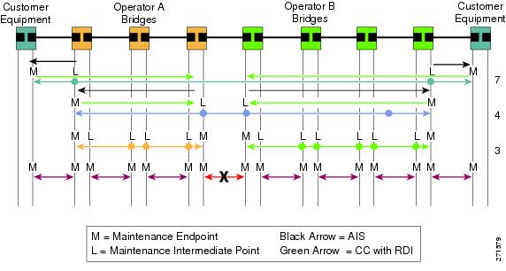
If the detected fault is due to Dying gasp, the link will go down in both directions creating AIS and RDI frame flow as shown in the figure below.
ETH-RDI
ETH-RDI can be used by a MEP to communicate to its peer MEPs that a defect condition has been encountered. ETH-RDI is used only when Ethernet OAM Continuity Check (ETH-CC) transmission is enabled.
ETH-RDI has the following two applications:
- Single-ended fault management--The receiving MEP detects a RDI defect condition, which gets correlated with other defect conditions in this MEP and may become a fault cause. The absence of received ETH-RDI information in a single MEP indicates the absence of defects in the entire MA.
- Contribution to far-end performance monitoring--It reflects that there was a defect condition in the far end, which is used as an input to the performance monitoring process.
A MEP that is in a defect condition transmits frames with ETH-RDI information. Upon receiving frames with ETH-RDI information, a MEP determines that its peer MEP has encountered a defect condition. However, for multipoint Ethernet connectivity, a MEP, upon receiving frames with ETH-RDI information, cannot determine the associated subset of its peer MEPs with which the MEP transmitting RDI information encounters defect conditions, as the transmitting MEP itself does not always have that information.
CCM Information
CFM continuity check messages (CCMs) are messages exchanged among MEPs. They allow MEPs to discover other MEPs within a domain and allow MIPs to discover MEPs.
CFM CCMs have the following characteristics:
- Transmitted at a configurable periodic interval by MEPs. The interval can be from 10 seconds to 65535 seconds, the default is 30.
- Contain a configurable hold time value to indicate to the receiver the validity of the message. The default hold time value is 3.5 times the transmit interval.
- Catalogued by MIPs at the same maintenance level.
- Terminated by remote MEPs at the same maintenance level.
- Unidirectional and do not solicit a response.
- Carries the status of the port on which the MEP is configured.
CCM with ETH-RDI Reception
Upon receiving a CCM frame, a MEP examines it to ensure that its MA Level corresponds to its configured MA Level and detects RDI condition if the RDI field is set. For a point-to-point Ethernet connection, a MEP can clear the RDI condition when it receives the first CCM frame from its peer MEP with the RDI field cleared. For multipoint Ethernet connectivity, a MEP can clear the RDI condition when it receives the CCM frames from its entire list of peer MEPs with the RDI fields cleared.
How to Configure ITU-T Y.1731 Fault Management Functions
Y.1731 fault management enhancements consist of ETH-AIS and ETH-RDI. Both enhancements are enabled by default when CFM is configured but each is enabled by a separate command during CFM configuration.
- ETH-AIS is enabled by default by the ethernet cfm enablecommand.
- ETH-RDI is enabled by default by the ethernet cfm cc enable level command.
Perform this task to change the default configuration.
- level level-id
- disable
- ethernet cfm ais domain domain-id [vlan vlan-id | evc evc-name]
DETAILED STEPS
How to Configure ITU-T Y.1731 Fault Management Functions
DETAILED STEPS
Configuration Examples for Configuring ITU-T Y.1731 Fault Management Functions
- Example Enabling Ethernet CFM on an Interface
- Examples show ethernet cfm Command Output
- Example Syslog AIS Message with Interface Name
Example Enabling Ethernet CFM on an Interface
!
ethernet cfm domain ServiceProvider level 4
mep archive-hold-time 60
service MetroCustomer1 vlan 100
!
ethernet cfm domain OperatorA level 1
mep archive-hold-time 65
service MetroCustomer1OpA vlan 100
!
ethernet cfm enable
ethernet cfm traceroute cache
ethernet cfm traceroute cache size 200
ethernet cfm traceroute cache hold-time 60
!
interface gigabitethernet3/0
ethernet cfm mip level 1
!
interface gigabitethernet4/0
ethernet cfm mip level 4
ethernet cfm mep level 1 mpid 102 vlan 100
!
ethernet cfm cc enable level 1 vlan 100
ethernet cfm cc level any vlan any interval 20 loss-threshold 3
Examples show ethernet cfm Command Output
Router# show ethernet cfm maintenance-points local detail

MEP Settings:
-------------
MPID: 2101
DomainName: PROVIDER_DOMAIN
Level: 4
Direction: I
Vlan: 101
Interface: Et0/1
CC-Status: Enabled
MAC: aabb.cc03.8410
Defect Condition: AIS
presentRDI: TRUE
AIS-Status: Enabled
AIS Period: 1000(ms)
AIS Expiry Threshold: 3.5
Level to transmit AIS: Default
Suppress Alarm configuration: Enabled
Suppressing Alarms: Yes
Router# show ethernet cfm smep interface
  Ethernet  IEEE 802.3
Router# show ethernet cfm smep
SMEP Settings:
--------------
Interface: Ethernet0/0
AIS-Status: Enabled
AIS Period: 60000 (ms)
Level to transmit AIS: 4
Defect Condition: No Defect
Router# show ethernet cfm error
Level Vlan      MPID   Remote MAC         Reason            Service ID
5     102       -      aabb.cc00.ca10     Receive AIS       service test
Router# show ethernet cfm maintenance-points remote detail mpid 66
MAC Address: aabb.cc00.ca10
Domain/Level: PROVIDER_DOMAIN/4
EVC: test
MPID: 66 (Can ping/traceroute)
Incoming Port(s): Ethernet0/2
CC Lifetime(sec): 75
Age of Last CC Message(sec): 8
Receive RDI: TRUE
Frame Loss: 0%
CC Packet Statistics: 2/0 (Received/Error)
R1#MAC Address: aabb.cc00.ca10
Domain/Level: PROVIDER_DOMAIN/4
EVC: test
MPID: 66 (Can ping/traceroute)
Incoming Port(s): Ethernet0/2
CC Lifetime(sec): 75
Age of Last CC Message(sec): 8
Receive RDI: TRUE
Frame Loss: 0%
CC Packet Statistics: 2/0 (Received/Error)
Example Syslog AIS Message with Interface Name
00:05:39: %ETHER_CFM-6-ENTER_AIS: local mep with mpid 101 level 4 id 7 dir I Interface Ethernet0/0 enters AIS defect condition
00:05:39: %ETHER_CFM-6-EXIT_AIS: local mep with mpid 101 level 4 id 7 dir I Interface Ethernet0/0 exitec AIS defect condition
00:05:39: %ETHER_CFM-6-ENTER_AIS_INT: Interface Ethernet0/0 enters AIS defect condition for outward direction
00:05:39: %ETHER_CFM-6-EXIT_AIS_INT: Interface Ethernet0/0 exited AIS defect condition for outward direction
Additional References
Related Documents
| Related Topic |
Document Title |
|---|---|
| Ethernet CFM |
Configuring Ethernet Connectivity Fault Management in a Service Provider Network |
| Using OAM |
Using Ethernet Operations, Administration, and Maintenance |
| Carrier Ethernet commands: complete command syntax, command mode, command history, defaults, usage guidelines, and examples |
Cisco IOS Carrier Ethernet Command Reference |
| Cisco IOS commands: master list of commands with complete command syntax, command mode, command history, defaults, usage guidelines, and examples |
Standards
| Standard |
Title |
|---|---|
| ITU-T |
ITU-T Y.1731 OAM Mechanisms for Ethernet-Based Networks |
MIBs
| MIB |
MIBs Link |
|---|---|
| No new or modified MIBs are supported by this feature, and support for existing MIBs has not been modified by this feature. |
To locate and download MIBs for selected platforms, Cisco software releases, and feature sets, use Cisco MIB Locator found at the following URL: |
RFCs
| RFC |
Title |
|---|---|
| No new or modified RFCs are supported by this feature, and support for existing RFCs has not been modified. |
-- |
Technical Assistance
| Description |
Link |
|---|---|
| The Cisco Support and Documentation website provides online resources to download documentation, software, and tools. Use these resources to install and configure the software and to troubleshoot and resolve technical issues with Cisco products and technologies. Access to most tools on the Cisco Support and Documentation website requires a Cisco.com user ID and password. |
Feature Information for Configuring ITU-T Y.1731 Fault Management Functions
The following table provides release information about the feature or features described in this module. This table lists only the software release that introduced support for a given feature in a given software release train. Unless noted otherwise, subsequent releases of that software release train also support that feature.
Use Cisco Feature Navigator to find information about platform support and Cisco software image support. To access Cisco Feature Navigator, go to www.cisco.com/go/cfn. An account on Cisco.com is not required.
| Table 1 | Feature Information for Configuring ITU-T Y.1731 Fault Management Functions |
| Feature Name |
Releases |
Feature Information |
|---|---|---|
| Configuring ITU-T Y.1731 Fault Management Functions |
12.2(33)SRD 12.2(50)SY |
The ITU-Y.1731 Fault Management Functions feature provides new functions for fault and performance management to serve the needs of service providers in large networks. These new functions extend Ethernet Alarm Indication Signal (ETH-AIS) and Ethernet Remote Defect Indication (ETH-RDI) to include fault detection, fault verification, and fault isolation for large Ethernet MANs and WANs. The following sections provide information about this feature: The following commands were introduced or modified: clear ethernet cfm ais , ethernet cfm ais link-status global, show ethernet cfm error, show ethernet cfm maintenance-points remote detail, show ethernet cfm smep interface. |
Cisco and the Cisco Logo are trademarks of Cisco Systems, Inc. and/or its affiliates in the U.S. and other countries. A listing of Cisco's trademarks can be found at www.cisco.com/go/trademarks. Third party trademarks mentioned are the property of their respective owners. The use of the word partner does not imply a partnership relationship between Cisco and any other company. (1005R)
Any Internet Protocol (IP) addresses and phone numbers used in this document are not intended to be actual addresses and phone numbers. Any examples, command display output, network topology diagrams, and other figures included in the document are shown for illustrative purposes only. Any use of actual IP addresses or phone numbers in illustrative content is unintentional and coincidental.
 Feedback