Feedback
Table Of Contents
Cisco IPICS Component Considerations
Allocation of RMS DS0 Resources
DSP Channel Optimization and Allocation
Examples of Hardware Configuration and Supported Voice Streams
Channel Mixing in the RMS using the Cisco Hoot `n' Holler Feature
Cisco IPICS Endpoint Scenarios
Cisco Unified CallManager Configuration Overview
Cisco CallManager Express Configuration Overview
Cisco IPICS Component Considerations
This chapter provides information about various components that can be part of a Cisco IPICS solution. This information will help you to understand how these components interoperate in a Cisco IPICS deployment.
This chapter includes these topics:
Router Media Service
The Cisco IPICS solution uses one or more of the supported IOS routers to provide the router media service (RMS) functionality.
The following sections provide additional information about the RMS:
•
Allocation of RMS DS0 Resources
For detailed information about configuring an RMS for Cisco IPICS, refer to the "RMS Configuration" appendix in Cisco IPICS Server Administration Guide.
For a list of IOS versions that Cisco IPICS supports for use as an RMS, refer to Cisco IPICS Compatibility Matrix. Each supported IOS version includes the Cisco Hoot `n' Holler feature.
RMS Overview
The primary role of an RMS is to provide media stream mixing by looping back DS0 resources. When an RMS is installed, it must have one or more pairs of T1 or E1 interfaces that are connected back to back with a T1 loopback cable. These loopback interface pairs are manually configured in the RMS by adding the DS0-Group to timeslot mapping. (For related information, refer to Cisco IPICS Server Administration Guide.) When you use the Cisco IPICS Administration Console to add an RMS, the loopback pairs are available for assignment. A properly configured RMS makes a list of DS0 loopback channels available for dynamic allocation by the Cisco IPICS server.
The RMS can be installed as a standalone component (RMS router) or as an additional feature that is installed in the LMR gateway.
The Cisco IPICS server dynamically allocates a DS0 loopback pair (two DS0 channels) in the following scenarios:
•
•
Supporting Locations
An RMS supports one Cisco IPICS location, which is defined as a multicast domain. If a Cisco IPICS deployment requires RMS functionality in more than one location, there must be an RMS for each of those locations. The multicast address pool contains a list of multicast addresses and their respective port assignments. The addresses in the pool are allocated as needed by the Cisco IPICS server when it configures an RMS. The Cisco IPICS server keeps track of the in-use and the available addresses.
The multicast address pool is a global resource. It is shared across each RMS that is configured in that Cisco IPICS server. Therefore, the network configuration must be able to support all of the configured addresses in each configured RMS. The Cisco IPICS server attempts to load balance across all RMS components that are in the same location.
The following information applies to locations:
•
•
•
Multiple Location Example
As an example of how Cisco IPICS and RMS components functions in multiple locations, consider the following scenario:
•
•
•
•
•
•
•
When the Cisco IPICS dispatcher activates VTG Emergency, the Cisco IPICS server assigns to the VTG a multicast address from the multicast address pool. It also configures DS0 loopback resources in RMS 1 and RMS 2.
In this way, users in both locations can communicate using the VTG. Be aware that this scenario requires that there must be multicast connectivity between both locations. If both locations are isolated multicast domains, there must be a way to route the multicast traffic between locations. For related information, see the "Multiple Site Model" section.
RMS Configuration Example
The following example shows what the Cisco IPICS server configures in an RMS when a VTG that contains two channels is activated. This example allows the RMS to receive voice on the Police channel and to transmit it to the VTG multicast address, and to receive voice on the VTG multicast address and to transmit it to the Police channel. In this example,
•
•
•
•
•
The following IOS configuration output shows what the Cisco IPICS server configured in the RMS to support putting the Police channel in the Combined VTG:
dial-peer voice 90929093 voipdescription #0/2/0:3#1164200525742# INUSE 284destination-pattern 90929093voice-class permanent 1session protocol multicastsession target ipv4:239.192.21.79:21000codec g711ulawno vadvoice-port 0/2/0:3voice-class permanent 1auto-cut-throughlmr m-lead audio-gate-inlmr e-lead voiceno echo-cancel enableplayout-delay maximum 100no comfort-noisetimeouts call-disconnect 3timeouts teardown lmr infinitytiming hookflash-in 0timing hangover 40connection trunk 90929093description #0/2/0:3#1164200525742# INUSE 284voice-port 0/2/1:3voice-class permanent 1auto-cut-throughlmr m-lead audio-gate-inlmr e-lead voiceno echo-cancel enableplayout-delay maximum 100no comfort-noisetimeouts call-disconnect 3timeouts teardown lmr infinitytiming hookflash-in 0timing hangover 40connection trunk 90929193description #0/2/1:3#1164200525742# INUSE 284dial-peer voice 90929193 voipdescription #0/2/1:3#1164200525742# INUSE 284destination-pattern 90929193voice-class permanent 1session protocol multicastsession target ipv4:239.192.21.64:21000codec g711ulawThe following IOS configuration output shows what the Cisco IPICS server configured in the RMS to support putting the Fire channel in the Combined VTG.
dial-peer voice 90929094 voipdescription #0/2/0:4#1164200525776# INUSE 285destination-pattern 90929094voice-class permanent 1session protocol multicastsession target ipv4:239.192.21.79:21000codec g711ulawno vadvoice-port 0/2/0:4voice-class permanent 1auto-cut-throughlmr m-lead audio-gate-inlmr e-lead voiceno echo-cancel enableplayout-delay maximum 100no comfort-noisetimeouts call-disconnect 3timeouts teardown lmr infinitytiming hookflash-in 0timing hangover 40connection trunk 90929094description #0/2/0:4#1164200525776# INUSE 285voice-port 0/2/1:4voice-class permanent 1auto-cut-throughlmr m-lead audio-gate-inlmr e-lead voiceno echo-cancel enableplayout-delay maximum 100no comfort-noisetimeouts call-disconnect 3timeouts teardown lmr infinitytiming hookflash-in 0timing hangover 40connection trunk 90929194description #0/2/1:4#1164200525776# INUSE 285dial-peer voice 90929194 voipdescription #0/2/1:4#1164200525776# INUSE 285destination-pattern 90929194voice-class permanent 1session protocol multicastsession target ipv4:239.192.21.65:21000codec g711ulawno vadThe following IOS configuration output examples show what the Cisco IPICS server configures in the RMS when a PMC user who is assigned both the Police and Fire channels connects using the remote location. This configuration allows the PMC to communicate with RMS using unicast. The RMS forwards the unicast stream, which is received from the PMC, through a DS0 loopback to the multicast address. Packets that the RMS receives for a multicast address are forwarded through a DS0 loopback to the receiving PMC device as unicast.
This IOS configuration output is for the Police channel:
dial-peer voice 909290914 voipdescription #0/2/0:14#1164659525783# INUSE 295destination-pattern 909290914voice-class permanent 1session protocol multicastsession target ipv4:239.192.21.64:21000codec g711ulawno vadvoice-port 0/2/0:14voice-class permanent 1auto-cut-throughlmr m-lead audio-gate-inlmr e-lead voiceno echo-cancel enableplayout-delay maximum 100no comfort-noisetimeouts call-disconnect 3timeouts teardown lmr infinitytiming hookflash-in 0timing hangover 40connection trunk 909290914voice-port 0/2/1:14voice-class permanent 1auto-cut-throughlmr m-lead audio-gate-inlmr e-lead voiceno echo-cancel enableplayout-delay maximum 100no comfort-noisetimeouts call-disconnect 3timeouts teardown lmr infinitytiming hookflash-in 0timing hangover 40description #0/2/1:14#1164659525783# INUSE 295dial-peer voice 909291914 potsdescription #0/2/1:14#1164659525783# INUSE 295destination-pattern 1990000275909291914port 0/2/1:14This IOS configuration output is for the Fire channel:dial-peer voice 909290915 voipdescription #0/2/0:15#1164659525833# INUSE 296destination-pattern 909290915voice-class permanent 1session protocol multicastsession target ipv4:239.192.21.65:21000codec g711ulawno vadvoice-port 0/2/0:15voice-class permanent 1auto-cut-throughlmr m-lead audio-gate-inlmr e-lead voiceno echo-cancel enableplayout-delay maximum 100no comfort-noisetimeouts call-disconnect 3timeouts teardown lmr infinitytiming hookflash-in 0timing hangover 40connection trunk 909290915description #0/2/0:15#1164659525833# INUSE 296voice-port 0/2/1:15voice-class permanent 1auto-cut-throughlmr m-lead audio-gate-inlmr e-lead voiceno echo-cancel enableplayout-delay maximum 100no comfort-noisetimeouts call-disconnect 3timeouts teardown lmr infinitytiming hookflash-in 0timing hangover 40description #0/2/1:15#1164659525833# INUSE 296dial-peer voice 909291915 potsdescription #0/2/1:15#1164659525833# INUSE 296destination-pattern 1990000275909291915port 0/2/1:15When is an RMS Required?
Cisco IPICS requires an RMS to establish connectivity between unicast and multicast endpoints (remote PMC to channel, remote PMC to VTG), and to establish connectivity between multicast endpoints that are on different channels (channel to VTG, VTG to VTG).
However, there are some communication scenarios that do not require RMS DS0 resources. For example, two multicast users can communicate on a single Cisco IPICS channel without consuming RMS DS0 resources, as illustrated in Figure 2-1. In this example, after the users log in to the Cisco IPICS server, they receive their channel information, which is Metro Police using the multicast group 239.192.21.64. If the users activate the Metro Police channel, they will be able to communicate without using RMS DS0 resources.
Figure 2-1 Single Cisco IPICS Channel
Adding an LMR gateway and an LMR user to this scenario does not necessarily require RMS DS0 resources. If the LMR user is statically configured to use the same channel as the other users, all users can communicate without consuming RMS DS0 resources, as shown in Figure 2-2.
Figure 2-2 Single Cisco IPICS Channel with LMR Gateway
As another example, a scenario with two sets of users on two separate channels does not consume RMS DS0 resources if communication between the channels is not required. In the scenario shown in Figure 2-3, Metro Police users can communicate with each other, and Metro Fire users can communicate with each other, without consuming RMS DS0 resources. In this scenario, no RMS resources are required because there is no communication between Metro Police and Metro Fire users.
Figure 2-3 Several Cisco IPICS Channels
Allocation of RMS DS0 Resources
You can create a VTG that allows only specific users to communicate by using that VTG. In this case, the VTG does not include channels and it does not use RMS DS0 resources (unless there are PMC users on the remote location), but it will use a multicast address from the multicast pool.
If a VTG needs to include LMR endpoints, each of the LMR channels must be added to the VTG, in addition to the channels for the PMC or phone users. If a user is not added to the VTG but has a channel that is in the VTG, the user will still be able to send to and receive from the VTG.
When a PMC successfully authenticates using the remote location, the RMS allocates a DS0 pair to each channel or VTG that is assigned to that authenticated PMC user. (See the "Remote PMC Users" section for related information.)
Table 2-1 describes when RMS resources are allocated in various scenarios.
DSP Channel Optimization and Allocation
Follow these recommendations for optimizing DS0 channels and DSP channels:
•
•
•
•
To help calculate the DSPs that you need for your configuration, refer to High-Density Packet Voice Digital Signal Processor Modules, which is available at the following URL:
http://www.cisco.com/en/US/products/hw/modules/ps3115/products_qanda_item0900aecd8016c6ad
.shtmlExamples of Hardware Configuration and Supported Voice Streams
This section provides examples of various hardware configurations and the number of voice streams that can be supported for use with Cisco IPICS.
When you use the Cisco 2811 with one T1/E1 Multiflex Trunk Voice/WAN Interface (VWIC-2MFT-T1/E1) card installed on the motherboard, up to 24 pairs of DS0 (bearer) channels are available for use if the card is configured for T1 mode. If the card is configured for E1 mode, up to 30 DS0 channels are available. The number of supported voice streams varies based on the configuration that you use. For example, with one 64-channel high-density Packet Voice/Fax DSP Module (PVDM2-64) installed, support is provided for up to 32 pairs of voice streams when using the G.711 u-law codec. If you use the G.729 u-law codec, the PVDM2-64 provides support for 16 pairs of voice streams. In this situation, one PVDM2-64 does not support full utilization of all pairs of DS0 channels on a T1 line.
The following options are also available for use with the Cisco 2811:
•
•
Note
For more information about Cisco interfaces and modules, go to the following URL:
http://www.cisco.com/en/US/products/hw/modules/prod_module_category_home.html
Virtual Talk Groups
A virtual talk group (VTG) enables participants on various channels to communicate by using a single multicast address. A VTG contains, in a temporary channel, any combination of the following members:
•
•
•
•
•
A Cisco IPICS administrator creates Cisco IPICS channels and assigns a multicast address to each one. A Cisco IPICS dispatcher creates VTGs as needed. When a dispatcher creates a VTG, the Cisco IPICS server automatically allocates to the VTG an available address from the multicast pool. So while VTGs are dynamically assigned addresses from the multicast pool, channels are configured as static addresses that are outside the range of the addresses that are used by VTGs.
A VTG allows communication between endpoints that are assigned different multicast addresses, such as two endpoints that have activated different channels. When a VTG is enabled to facilitate communications between two or more endpoints with different multicast addresses, an RMS must bridge, or mix, the multicast streams of each channel. In this VTG scenario, the Cisco IPICS sever allocates a loopback voice port for each channel in the VTG.
For example, assume that a dispatcher creates a VTG named "Combined" and that this VTG includes the Police channel and Fire channel as members. Also assume that each LMR voice port is statically configured with a multicast address, so that LMR police users always send to the Police channel, and LMR fire users always send to the Fire channel. To provide communication between the Police channel and the Fire channel, an RMS must bridge the multicast streams from these channels.
In this example, when a user talks on the Police channel (channel 1), the RMS router must bridge that multicast stream to the Fire channel (channel 2) and to the VTG channel. The RMS must perform similar operations when a user talks on channel 2 or on the VTG channel. See Figure 2-4.
Figure 2-4 VTG Channel Mixing
The RMS accomplishes this media mixing by using T1 or E1 interfaces, which are connected back to back with a T1 Loopback cable, as illustrated in Figure 2-5
Figure 2-5 RMS
In this scenario, the Cisco IPICS server automatically selects two DS0 pairs from the RMS router to use for mixing the channels. The Cisco IPICS server also configures associated voice ports and dial peers.
To continue this example, assume that Cisco IPICS selects timeslots 10 and 14 as shown:
T1 0/0:10 --------------T1 0/1:10VTG Combined San Jose Police239.192.21.79 239.192.21.64T1 0/0:14 --------------T1 0/1:14VTG Combined San Jose Fire239.192.21.79 239.192.21.65Also assume that the Cisco IPICS dispatcher places the following users and channels into the Combined VTG channel:
•
–
–
•
–
–
–
–
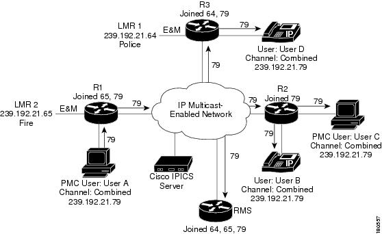
When the dispatcher activates this VTG, Cisco IPICS uses the Cisco router to configure on the RMS the voice ports and dial peers that are associated with the selected T1 DS0s. See Figure 2-6 and the configuration example that follows this figure.
Figure 2-6 RMS Configuration and Management
The following example shows configurations for this scenario:
dial-peer voice 90929090 voip
 description #0/0:10#1152296144646# INUSE 16
 destination-pattern 90929090
 voice class permanent 1
session protocol multicastsession target ipv4:239.192.21.79:21000codec g711ulawno vad ! dial-peer voice 90929190 voip description #0/1:10#1152296144646# INUSE 16 destination-pattern 90929190 voice class permanent 1session protocol multicast session target ipv4:239.192.21.65:21000 codec g711ulaw no vad ! dial-peer voice 90929092 voip description #0/0:14#1152296144696# INUSE 18 destination-pattern 90929092 voice class permanent 1session protocol multicast session target ipv4:239.192.21.79:21000 codec g711ulaw no vad ! dial-peer voice 90929192 voip description #0/1:14#1152296144696# INUSE 18 destination-pattern 90929192 voice class permanent 1session protocol multicast session target ipv4:239.192.21.64:21000 codec g711ulaw no vad!voice-port 0/0:10 voice class permanent 1auto-cut-through lmr m-lead audio-gate-in lmr e-lead voice no echo-cancel enable playout-delay maximum 100 no comfort-noise timeouts call-disconnect 3 timing hookflash-in 0 timing hangover 40 connection trunk 90929090 description #0/0:10#1152296144646# INUSE 16 ! voice-port 0/0:14 voice class permanent 1auto-cut-through lmr m-lead audio-gate-in lmr e-lead voice no echo-cancel enable playout-delay maximum 100 no comfort-noise timeouts call-disconnect 3 timeouts teardown lmr infinity timing hookflash-in 0 timing hangover 40 connection trunk 90929092 description #0/0:14#1152296144696# INUSE 18! voice-port 0/1:10 voice class permanent 1auto-cut-through lmr m-lead audio-gate-in lmr e-lead voice no echo-cancel enable playout-delay maximum 100 no comfort-noise timeouts call-disconnect 3 timing hookflash-in 0 timing hangover 40 connection trunk 90929190 description #0/1:10#1152296144646# INUSE 16voice-port 0/1:14 !voice class permanent 1auto-cut-through lmr m-lead audio-gate-in lmr e-lead voice no echo-cancel enable playout-delay maximum 100 no comfort-noise timeouts call-disconnect 3 timeouts teardown lmr infinity timing hookflash-in 0 timing hangover 40 connection trunk 90929192 description #0/1:14#1152296144696# INUSE 18Channel Mixing in the RMS using the Cisco Hoot `n' Holler Feature
The RMS uses the Cisco Hoot `n' Holler feature to mix channels. Cisco Hoot 'n' Holler is a communications system in which the three most recent talkers are mixed into one multicast output stream. Also known as hootie, these networks provide "always on" multi-user conferences without requiring that users dial in to a conference.
For additional information about Cisco Hoot `n' Holler, refer to the documentation at the following URLs:
•
http://www.cisco.com/en/US/products/ps6552/products_ios_technology_home.html
•
http://www.cisco.com/en/US/tech/tk828/tsd_technology_support_protocol_home.html
•
http://www.cisco.com/warp/public/cc/so/neso/vvda/hthllr/hhoip_wp.pdf
A virtual interface (VIF) is used to associate an IP address with the voice ports on the RMS. In the example shown in Figure 2-4, the RMS joins channels Police (239.192.21.64), Fire (239.192.21.65), and the Combined VTG (239.192.21.79).
In the Cisco Hoot `n' Holler over IP implementation, all participants in a VTG can speak simultaneously, However, when voice packets from various sources arrive at the router, the IOS arbitration algorithm selects only the three most active voice streams and presents them to the router DSP for mixing. If other voice streams are present, the router drops the longest talker in by using a round-robin arbitration algorithm. See Figure 2-7.
Figure 2-7 Mixing Voice Streams
Table 2-2 shows an example of how mixing works in a VTG that has four active users on a channel.
Cisco IPICS Endpoint Scenarios
When a Cisco IPICS dispatcher activates the Combined VTG (as shown in Figure 2-3), Cisco IPICS configures the RMS router to mix the Police, Fire, and Combined VTG channels. Users that have been added to the VTG see the new Combined VTG channel on their PMCs or Cisco Unified IP Phones. LMR endpoints do not have associated users. An LMR channel is statically configured, so an LMR user can send and receive only from the Cisco IPICS channel that is configured with the same multicast address as the LMR channel. An LMR user can communicate only with endpoints that are not using the same channel if the channel of the LMR user is in a VTG with other channels or users.
Figure 2-8 illustrates a scenario in which four users have deactivated their police or fire channels and have activated the Combined VTG channel.
Figure 2-8 Multicast Group Membership
When a user deactivates the Police and or Fire channel and activates the Combined VTG channel, the endpoint sends an Internet Group Management Protocol (IGMP) leave message for the Police and or Fire Channel and an IGMP join message for the Combined VTG channel. The LMR voice port channels are statically configured and the VIF will have already joined the configured multicast group. As shown in Figure 2-9, when user A transmits, the system sends the multicast packets via the multicast distribution tree to each endpoint that has joined the combined group, and to the RMS, which mixes the audio and sends it to the channels in the VTG.
Figure 2-9 Transmitting to the VTG Channel
When the RMS router receives the traffic over the Combined VTG channel, it mixes this channel with the Police and Fire channels and forwards the mixed stream to the LMR endpoints, as shown in Figure 2-10.
Figure 2-10 Transmitting VTG Channel to Police and Fire Channels
When the LMR Police user transmits, the only other endpoint that has joined this multicast channel is the RMS router. The Multicast Distribution tree forwards the multicast voice traffic to the RMS, where it is mixed with the Fire channel and the Combined VTG channel and then forwarded to the other endpoints in the VTG. See Figure 2-11.
Figure 2-11 LMR Multicast Traffic Flow
Figure 2-12 shows User C with two active channels: the Fire channel and the Combined VTG channel.
Figure 2-12 Traffic Flow with Two Active Channels
Because User C activated two channels (Fire and the Combined VTG), two multicast groups are joined through IGMP. As a result, when an endpoint in the Combined VTG transmits, User C will receive the transmitted packets twice. (In the case, the duplicate packets can cause audio quality issues. Take care to avoid this scenario.)
If there are no LMR endpoints in a VTG, RMS DS0 resources may not be required for the VTG. For example, consider a financial institution with one Cisco IPICS channel called Stocks and one channel called Bonds. The users that are associated with the Stocks channel can communicate with each other and the users that are associated with the Bonds channel can communicate with each other. Figure 2-13 illustrates this scenario.
Figure 2-13 Cisco IPICS Scenario with no LMR Endpoints
If a VTG is created that contains users but no channels, RMS DS0 resources are not required. The only resource that is required in this case is a multicast channel from the multicast pool. RMS DS0 resources are not needed because PMC and Cisco Unified IP Phone users, unlike LMR users, are not statically configured for one channel. If users only are placed in the VTG, users see the VTG on their PMCs or phones. When the VTG is activated, these endpoints will simply join the VTG multicast channel that is allocated by the Cisco IPICS server. See Figure 2-14.
Figure 2-14 VTG with Users Only
You can also avoid consuming RMS DS0 resources by creating a new channel and associating all users with that channel, instead of creating a VTG. In the example shown in Figure 2-14, there is a channel called Combined. Users see two channels on their PMCs or phones: the Combined VTG channel, and either the Stocks channel or the Bonds channel.
If you do not want a user (for example, User C) to participate in such a combined VTG channel, you can take either of these actions:
•
•
See Figure 2-15.
Figure 2-15 Restricting VTG Access
If you create a VTG that includes the Stocks channel, the Bonds channel, and all users except User C, all of the users except User C will see the Combined VTG channel on their PMCs or phones. However, because the Stocks channel and the Bonds channel are in the VTG, User C will be able to receive from and transmit to the VTG. See Figure 2-16.
Figure 2-16 Combined VTG with a User Omitted
Remote PMC Users
PMC users who are not connected to the Cisco IPICS multicast domain must choose the remote location when they log in to Cisco IPICS, as shown in Figure 2-17. A PMC user that is logged into Cisco IPICS in this way is sometimes called a remote PMC user. Examples of such users include those using a satellite connection or those connecting the network through a VPN.
Figure 2-17 Remote PMC User
A remote PMC user cannot connect to the Cisco IPICS domain using multicast. Instead, the remote PMC user connects to the RMS by using a SIP-based (unicast) connection. The RMS then mixes the unicast stream to a multicast stream for the channel that the remote PMC user activated. After the remote PMC user logs into Cisco IPICS, the Cisco IPICS server allocates a DS0 pair on the RMS for every channel that is associated with the user. See Figure 2-18.
Figure 2-18 Timeslot Allocation
Assume that the Cisco IPICS server allocates timeslot 20 for the remote PMC user. In this case, the Cisco IPICS server configures the voice ports and dial peers as follows:
Multicast Side—239.192.21.64
voice-port 0/0/0:20voice class permanent 1auto-cut-throughlmr m-lead audio-gate-inlmr e-lead voiceno echo-cancel enableplayout-delay maximum 100no comfort-noisetimeouts call-disconnect 3timing hookflash-in 0timing hangover 40connection trunk 909090920description #0/0/0:20#1123534375842# INUSE 92dial-peer voice 909090920 voipdescription #0/0/0:20#1123534375842# INUSE 92destination-pattern 909090920voice class permanent 1session protocol multicastsession target ipv4:239.192.21.64:21000codec g711ulawno vadUnicast Side—239.192.21.64
voice-port 0/0/1:20voice class permanent 1auto-cut-throughlmr m-lead audio-gate-inlmr e-lead voiceno echo-cancel enableplayout-delay maximum 100no comfort-noisetimeouts call-disconnect 3timing hookflash-in 0timing hangover 40description #0/0/1:20#1123534375842# INUSE 92dial-peer voice 909091920 potsdescription #0/0/1:20#1123534375842# INUSE 92destination-pattern 8880000081909091920port 0/0/1:20After the Cisco IPICS server configures the voice ports and the dial peers, it sends to the remote PMC user the IP address of the RMS and the Plain Old Telephone Service (POTS) number for the unicast connection. See Figure 2-19.
Figure 2-19 Providing RMS and POTS Number to Remote User
When a channel is activated by a remote PMC user, the remote PMC uses the SIP to set up the unicast call. After the SIP call is established, the remote PMC user can send to and receive from the Police channel.
For an example of this process, see the following figures:
•
•
•
•
Figure 2-20 Unicast Connection Set Up
Figure 2-21 SIP Signaling Flow
Figure 2-22 Unicast to Multicast Call Flow
Figure 2-23 Multicast to Unicast Call Flow
When you add an RMS on the Cisco IPICS server, use the loopback address of the RMS router. If there are several paths to the RMS router and a physical interface is used, the RMS will be unreachable if the physical interface goes down or becomes unreachable. If the loopback address is used as the IP address when adding the RMS on the Cisco IPICS server, that server will push this IP address to the PMCs as the SIP proxy address.
Land Mobile Radio Gateway
The Cisco Hoot `n' Holler feature is used to enable land mobile radios (LMRs) in a Cisco IPICS solution. An LMR is integrated by providing an ear and mouth (E&M) interface to an LMR or to other PTT devices, such as Sprint and Nextel phones. This interface is in the form of a voice port that is configured to provide an appropriate electrical interface to the radio. The voice port is configured with a connection trunk entry that corresponds to a VoIP dial peer, which in turn associates the connection to a multicast address. You can configure a corresponding channel in Cisco IPICS, using the same multicast address, which enables Cisco IPICS to provide communication paths between the desired endpoints.
For additional information about LMRs, refer to the documentation at this URL:
Cisco Unified IP Phones
If your Cisco IPICS deployment includes Cisco Unified CallManager or Cisco CallManager Express, you can use the Cisco Unified IP Phone services application programming interface (API) to provide PTT capabilities to certain Cisco Unified IP Phone models. A phone with the PTT capability enabled can function similarly to a PMC, providing an easy-to-use GUI that allows users to monitor or participate in a PTT channels or VTG over a VoIP network. However, unlike a PMC, a phone can participate in only one channel or VTG at a time. To participate in a channel or VTG, a phone user chooses the desired channel or VTG from a list that is displayed on the phone.
A phone that is configured to work as a PTT device uses a stand-alone LMR PTT audio client. This Extensible Markup Language (XML) application enables the display of interactive content with text and graphics on the phone.
To enable this feature, Cisco Unified CallManager or Cisco CallManager Express must be deployed in your IP telephony (IPT) network, and either of these applications must be configured with the IP address of the Cisco IPICS server. A Cisco Unified IP Phone use this IP address to locate the server and download the PTT XML application.
For related information about configuring this feature, refer to the "Setting Up the Cisco IP Phone for use with Cisco IPICS" appendix in Cisco IPICS Server Administration Guide. For a list of Cisco Unified IP Phones that Cisco IPICS supports as PTT devices, refer to Cisco IPICS Compatibility Matrix. These documents are available at the following URL:
http://www.cisco.com/univercd/cc/td/doc/product/cis/c_ipics/index.htm
Cisco Unified CallManager Configuration Overview
You use the Cisco IP Phone Services Configuration page in the Cisco Unified CallManager Administration application to define and maintain the list of Cisco Unified IP Phone services to which users can subscribe. These services are XML applications that enable the display of interactive content on supported models of a Cisco Unified IP Phone.
Figure 2-24 shows the Cisco IP Phone Services page.
Figure 2-24 Cisco IP Phone Services Configuration Page
After you configure a list of IP phone services, Cisco Unified IP Phone users can access the Cisco Unified CallManager User Options menu and subscribe to the services, or an administrator can add services to Cisco Unified IP Phones and device profiles. Administrators can assign services to speed-dial buttons so that users have one-button access to the services.
For detailed information about configuring phone services, refer to the "Cisco IP Phone Services" chapter in Cisco Unified CallManager System Guide, which is available at this URL:
http://www.cisco.com/univercd/cc/td/doc/product/voice/c_callmg/
Cisco CallManager Express Configuration Overview
The following is a sample IOS router configuration that enables Cisco CallManager Express to support a Cisco Unified IP Phone as a Cisco IPICS PTT device:
ip dhcp excluded-address 10.1.1.1
!
ip dhcp pool pool1
network 10.1.1.0 255.255.255.248
domain-name yourdomainname
dns-server dns1 dns2
default-router 10.1.1.1
option 150 ip 10.1.1.1
tftp-server flash:filename1
tftp-server flash:filename2
telephony-service
load 7960-7940 filename1
load 7970 filename2
max-ephones n
max-dn m
ip source-address 10.1.1.1 port 2000
auto assign 1 to n
url services http://10.1.2.1/ipics_server/servlet/IPPhoneManager
create cnf-files
max-conferences 8 gain -6
ephone-dn 1 dual-line
number abcd
!
ephone-dn 2 dual-line
number efgh