Feedback Feedback
|
Table Of Contents
Troubleshooting ATM LAN Emulation Networks
Troubleshooting a LAN Emulation Network
Troubleshooting LECs Not Coming Up
LANE Client Connection Example, with debug lane client all Enabled
ATM Addresses Used in This debug Output
Connecting to LECS (Configure Direct)
Connecting to LES (Control Direct) and Back from LES (Control Distribute)
Understanding the show lane client Output
Understanding the LE_ARP Process
Before Calling Cisco Systems' TAC Team
Additional Sources of Information
Troubleshooting ATM LAN Emulation Networks
This chapter introduces general troubleshooting techniques related to LAN Emulation (LANE) networks.
We will first briefly introduce LANE as it was conceived: a LAN technology aimed at emulating a legacy Ethernet network over ATM. We will then cover troubleshooting of the most common problems using this technology:
•
Troubleshooting LANE Clients not coming up
•
Introduction
LANE is a standard defined by the ATM Forum that provides ATM-attached stations the same capabilities that they normally obtain from legacy Ethernet LANs. As the name suggests, the function of the LANE protocol is to emulate a LAN on top of an ATM network. By making an ATM interface look like one or more separate Ethernet interfaces, LANE enables LAN users to take advantage of ATM's benefits without requiring modifications to end-station hardware or software.
ATM is a connection-oriented service that establishes connections between source and destination devices. LAN-based protocols, on the other hand, are connectionless and use broadcasts so that source devices can find one or more destination devices. The primary purpose of LANE, then, is to provide the same services that a broadcast medium such as Ethernet does.
The LANE protocol resolves MAC addresses to ATM addresses so that LANE end systems can set up direct connections between themselves and then can forward data. The LANE protocol can be deployed in two types of ATM-attached equipment:
•
•
The LANE specification defines several components that enable the protocol to provide the broadcast and address resolution services required to emulate traditional LANs:
•
•
•
Note
•
Troubleshooting a LAN Emulation Network
Though not very complex in theory, the different configurations necessary to implement a LANE network include a lot of long ATM addresses. It becomes easy to insert a typo that will cause the whole setup to fail. Very often, then, troubleshooting a LANE network simply means to have it work! For this reason, this part is split in two sections:
•
•
Troubleshooting LECs Not Coming Up
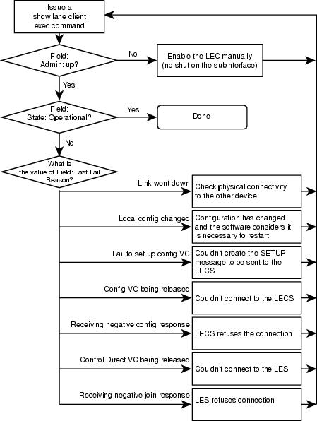
The flowchart shown in Figure 21-1 explains which section to use in this section. Issue a show lane client exec command on the device hosting the LEC. Use the field Last Fail Reason, and jump to the corresponding section in next table (the show lane client command is fully described in the section "Understanding the show lane client Output," later in this chapter). If you could not solve your issue by simply following the flowchart, refer to the entry "If None of This Works," in Table 21-1.
Figure 21-1 Flowchart Explaining How to Troubleshoot a LEC Not Coming Up
Annex: Commands and Examples
In this section, we'll give examples of the most common ebug and show commands used when troubleshooting LANE.
LANE Client Connection Example, with debug lane client all Enabled
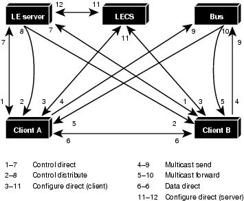
Figure 21-2 shows VCs required for LANE to work.
Figure 21-2 Example of VCs Required for LANE to Work
This is the sequence of events that needs to happen for LEC to come up from LEC's perspective, which is shown in debug lane client all:
1.
2.
3.
4.
5.
6.
ATM Addresses Used in This debug Output
The ATM addresses of the LECS/LES/BUS/LEC used in this example are shown below.
LECS 47.00918100000000603E899601.00E01E2EE8B3.00LES 47.00918100000000603E899601.00E01E2EE8B1.01BUS 47.00918100000000603E899601.00E01E2EE8B2.01LEC 47.00918100000000603E899601.00E01E2EE8B0.01ELAN Name Elan1Address Registration via ILMI
The LEC first registers its ATM address with the ATM network.
LEC ATM0.1: action A_REGISTER_ADDRLEC ATM0.1: predicate PRED_LEC_NSAP TRUELEC ATM0.1: state IDLE event LEC_LOCAL_ACTIVATE => REGISTER_ADDRLEC ATM0.1: action A_POST_LISTENLEC ATM0.1: sending LISTENLEC ATM0.1: listen on 47.00918100000000603E899601.00E01E2EE8B0.01LEC ATM0.1: state REGISTER_ADDR event LEC_CTL_ILMI_SET_RSP_POS => POSTING_LISTENLEC ATM0.1: received LISTENLEC ATM0.1: action A_ACTIVATE_LECLEC ATM0.1: predicate PRED_CTL_DIRECT_NSAP FALSELEC ATM0.1: predicate PRED_LECS_NSAP FALSELEC ATM0.1: state POSTING_LISTEN event LEC_SIG_LISTEN_POS => GET_LECS_ADDRLEC ATM0.1: action A_ALLOC_LECS_ADDRLEC ATM0.1: state GET_LECS_ADDR event LEC_CTL_ILMI_SET_RSP_POS => GET_LECS_ADDRConnecting to LECS (Configure Direct)
The LEC sets up a connection to LECS (bidirectional point-to-point VC) to find the ATM address of the LES for its ELAN. When this is done, this VC to the LECS is released.
The LEC finds the LECS ATM address by using three methods, in this order:
1.
2.
3.
Using the same VCC, the LECS returns the ATM address of the LES for the LEC ELAN.
In this debug output, the LEC is getting LECS address via ILMI:
LEC ATM0.1: action A_SEND_LECS_SETUPLEC ATM0.1: sending SETUPLEC ATM0.1: callid 0x40518C04LEC ATM0.1: called party 47.00918100000000603E899601.00E01E2EE8B3.00 LECS addressLEC ATM0.1: calling_party 47.00918100000000603E899601.00E01E2EE8B0.01 LEC addressLEC ATM0.1: state GET_LECS_ADDR event LEC_CTL_ILMI_SET_RSP_NEG => LECS_CONNECTLEC ATM0.1: received CONNECTLEC ATM0.1: callid 0x40518C04LEC ATM0.1: vcd 884LEC ATM0.1: action A_SEND_CFG_REQLEC ATM0.1: sending LANE_CONFIG_REQ on VCD 884LEC ATM0.1: SRC MAC address 00e0.1e2e.e8b0 LEC's MAC addressLEC ATM0.1: SRC ATM address 47.00918100000000603E899601.00E01E2EE8B0.01LEC ATM0.1: LAN Type 1LEC ATM0.1: Frame size 1LEC ATM0.1: LAN Name elan1 elan LEC is trying to joinLEC ATM0.1: LAN Name size 5LEC ATM0.1: state LECS_CONNECT event LEC_SIG_CONNECT => GET_LES_ADDRLEC ATM0.1: received LANE_CONFIG_RSP on VCD 884LEC ATM0.1: SRC MAC address 00e0.1e2e.e8b0LEC ATM0.1: SRC ATM address 47.00918100000000603E899601.00E01E2EE8B0.01LEC ATM0.1: LAN Type 1LEC ATM0.1: Frame size 1LEC ATM0.1: LAN Name elan1LEC ATM0.1: LAN Name size 5LEC ATM0.1: action A_PROCESS_CFG_RSPLEC ATM0.1: sending RELEASELEC ATM0.1: callid 0x40518C04LEC ATM0.1: cause code 31LEC ATM0.1: state GET_LES_ADDR event LEC_CTL_CONFIG_RSP_POS => LECS_RELEASELEC ATM0.1: received RELEASE_COMPLETELEC ATM0.1: callid 0x40518C04LEC ATM0.1: cause code 16Connecting to LES (Control Direct) and Back from LES (Control Distribute)
In the next step, the LEC establishes a VC to the LES (called the control direct). It then waits for the LES to add itself to the multipoint VC between the LES and all LECs (called the control distribute).
•
•
•
LEC ATM0.1: action A_SEND_LES_SETUPLEC ATM0.1: sending SETUP Control Direct (LEC to LES)LEC ATM0.1: callid 0x40518E74LEC ATM0.1: called party 47.00918100000000603E899601.00E01E2EE8B1.01 LES addressLEC ATM0.1: calling_party 47.00918100000000603E899601.00E01E2EE8B0.01 LEC addressLEC ATM0.1: state LECS_RELEASE event LEC_SIG_RELEASE_COMP => CTL_DIRECT_CONNLEC ATM0.1: received CONNECTLEC ATM0.1: callid 0x40518E74LEC ATM0.1: vcd 889LEC ATM0.1: action A_SEND_JOIN_REQLEC ATM0.1: sending LANE_JOIN_REQ on VCD 889LEC ATM0.1: Status 0LEC ATM0.1: LECID 0LEC ATM0.1: SRC MAC address 00e0.1e2e.e8b0LEC ATM0.1: SRC ATM address 47.00918100000000603E899601.00E01E2EE8B0.01LEC ATM0.1: LAN Type 1LEC ATM0.1: Frame size 1LEC ATM0.1: LAN Name elan1LEC ATM0.1: LAN Name size 5LEC ATM0.1: state CTL_DIRECT_CONN event LEC_SIG_CONNECT => JOIN_CTL_DIST_CONNLEC ATM0.1: received SETUP Control Distribute (LES to LEC)LEC ATM0.1: callid 0x404DC0A8LEC ATM0.1: called party 47.00918100000000603E899601.00E01E2EE8B0.01LEC ATM0.1: calling_party 47.00918100000000603E899601.00E01E2EE8B1.01LEC ATM0.1: action A_PROCESS_CTL_DIST_SETUPLEC ATM0.1: sending CONNECTLEC ATM0.1: callid 0x404DC0A8LEC ATM0.1: vcd 890LEC ATM0.1: state JOIN_CTL_DIST_CONN event LEC_SIG_SETUP => JOINLEC ATM0.1: received CONNECT_ACKLEC ATM0.1: state JOIN event LEC_SIG_CONNECT_ACK => JOINLEC ATM0.1: received LANE_JOIN_RSP on VCD 889LEC ATM0.1: Status 0LEC ATM0.1: LECID 1LEC ATM0.1: SRC MAC address 00e0.1e2e.e8b0LEC ATM0.1: SRC ATM address 47.00918100000000603E899601.00E01E2EE8B0.01LEC ATM0.1: LAN Type 1LEC ATM0.1: Frame size 1LEC ATM0.1: LAN Name elan1LEC ATM0.1: LAN Name size 5Obtaining BUS Address
In the next step, the LEC establishes a VC to the BUS (called the multicast send). It then waits for the BUS to add itself to the multipoint VC between the BUS and all LECs (called the multicast forward).
•
•
•
•
LEC ATM0.1: action A_PROCESS_JOIN_RSP_SEND_REQLEC ATM0.1: sending LANE_ARP_REQ on VCD 889LEC ATM0.1: SRC MAC address 00e0.1e2e.e8b0LEC ATM0.1: SRC ATM address 47.00918100000000603E899601.00E01E2EE8B0.01 LES addressLEC ATM0.1: TARGET MAC address ffff.ffff.ffff Broadcast addressLEC ATM0.1: TARGET ATM address 00.000000000000000000000000.000000000000.00 NSAP address is emptyLEC ATM0.1: state JOIN event LEC_CTL_JOIN_RSP_POS => GET_BUS_ADDRLEC ATM0.1: received LANE_ARP_RSP on VCD 890LEC ATM0.1: SRC MAC address 00e0.1e2e.e8b0LEC ATM0.1: SRC ATM address 47.00918100000000603E899601.00E01E2EE8B0.01LEC ATM0.1: TARGET MAC address ffff.ffff.ffffLEC ATM0.1: TARGET ATM address 47.00918100000000603E899601.00E01E2EE8B2.01 BUS address is filled inLEC ATM0.1: action A_SEND_BUS_SETUPLEC ATM0.1: predicate PRED_MCAST_SEND_NSAP FALSELEC ATM0.1: sending SETUP Mulitcast Send (LEC to BUS)LEC ATM0.1: callid 0x40506F14LEC ATM0.1: called party 47.00918100000000603E899601.00E01E2EE8B2.01LEC ATM0.1: calling_party 47.00918100000000603E899601.00E01E2EE8B0.01LEC ATM0.1: state GET_BUS_ADDR event LEC_CTL_ARP_RSP => MCAST_SEND_FORWARD_CONNLEC ATM0.1: received CONNECTLEC ATM0.1: callid 0x40506F14LEC ATM0.1: vcd 893LEC ATM0.1: action A_PROCESS_BUS_CONNECTLEC ATM0.1: state MCAST_SEND_FORWARD_CONN event LEC_SIG_CONNECT => MCAST_FORWARD_CONNLEC ATM0.1: received SETUP Mulitcast Forward (BUS to LEC)LEC ATM0.1: callid 0x4051B580LEC ATM0.1: called party 47.00918100000000603E899601.00E01E2EE8B0.01LEC ATM0.1: calling_party 47.00918100000000603E899601.00E01E2EE8B2.01LEC ATM0.1: action A_SEND_BUS_CONNECTLEC ATM0.1: sending CONNECTLEC ATM0.1: callid 0x4051B580LEC ATM0.1: vcd 894LEC ATM0.1: state MCAST_FORWARD_CONN event LEC_SIG_SETUP => ACTIVELEC ATM0.1: received CONNECT_ACKLEC ATM0.1: action A_PROCESS_CONNECT_ACKLEC ATM0.1: state ACTIVE event LEC_SIG_CONNECT_ACK => ACTIVELANE Client Is Operational
After all these steps have been completed, the LEC is UP and Operational. We can see this using the following command:
Cat5000_LANE>#show lane clientLE Client ATM0.1 ELAN name: elan1 Admin: up State: operationalClient ID: 1 LEC up for 10 minutes 0 secondJoin Attempt: 759HW Address: 00e0.1e2e.e8b0 Type: ethernet Max Frame Size: 1516VLANID: 100ATM Address: 47.00918100000000603E899601.00E01E2EE8B0.01VCD rxFrames txFrames Type ATM Address0 0 0 configure 47.00918100000000603E899601.00E01E2EE8B3.00889 1 2 direct 47.00918100000000603E899601.00E01E2EE8B1.01890 4 0 distribute47.00918100000000603E899601.00E01E2EE8B1.01893 0 317 send 47.00918100000000603E899601.00E01E2EE8B2.01894 9 0 forward 47.00918100000000603E899601.00E01E2EE8B2.01Understanding the show lane client Output
This command is by far the most important when it comes to LANE troubleshooting. On the TAC page, the Output Interpreter will decode the output for you. We will describe the most important fields here.
Let's focus on the following output:
Gambrinus#sh lane clientLE Client ATM2/0/0 ELAN name: default Admin: up State: operationalClient ID: 2 LEC up for 15 minutes 39 secondsELAN ID: 1Join Attempt: 691Last Fail Reason: Control Direct VC being releasedHW Address: 0060.4750.8402 Type: ethernet Max Frame Size: 1516ATM Address: 47.009181000000006047508401.006047508402.00VCD rxFrames txFrames Type ATM Address0 0 0 configure 47.009181000000006047508401.006047508405.00256 1 10 direct 47.009181000000006047508401.000000000002.01257 476 0 distribute 47.009181000000006047508401.000000000002.01258 0 56 send 47.009181000000006047508401.000000000003.01259 2 0 forward 47.009181000000006047508401.000000000003.01263 1 18 data 47.009181000000006047508401.006047508402.001.
We can see that the client is administratively up and is operational. As we've seen earlier in this chapter, this is the right state; it is up and running.
2.
The only thing to keep in mind here is that the LEC is up for only 15 minutes. Is this normal? Did a maintenance action happen 15 minutes ago?
3.
Although scary, this does not necessarily indicate that the LEC went down 691 times. The LECS/LES was perhaps unreachable for a long amount of time.
4.
This precious field indicates that the last reason for which the LEC could not reach the "UP/Operational" state was because it could not reach the LES
5.
This is interesting only when we check other LECs' sh lane client to find that the remote side of a data direct is this station.
6.
This line gives detail on the connection to the LECS; this VCC is called the configure direct, as the Type field suggests. The VCD number is 0 because the connection is torn down, per the spec.
7.
This line gives details on the connection to the LES; this VCC is called the control direct, as suggested by the Type field.
8.
This line gives details on the connection from the LES to all LECs. It is called the control distribute. We can see that the LES address is the same for the control direct and control distribute, as it should be.
9.
This line gives details on the connection to the BUS. It is called multicast send, as the Type field suggests.
10.
This line gives details on the connection from the BUS to all LECs. It is called multicast forward. We can see that the BUS address is the same for the multicast send and multicast forward.
11.
The remaining lines give details on each data direct VCC. Refer to the section "Understanding the LE_ARP Process" for more details.
Understanding the LE_ARP Process
The LAN Emulation Address Resolution Protocol is one of the most important in LANE. When a LEC must forward a unicast frame (that is, a frame with the destination MAC address set to the real MAC address), it should not forward it to the BUS.
Practically, it will try to create a mapping between this destination MAC address and the ATM address of the LEC to be contacted to reach this station. The LEC can be a LANE module, a router, or a directly attached station. This process is called LE_ARP. Waiting for this process to complete, the source LEC will forward the traffic to the BUS as unknown traffic.
Let's examine this in details. Say that we have the following topology:
IP station-----(ethernet connection)-----catalyst----(ATM lane module)------ls1010
10.200.10.61
As you can see, the LANE Client is up and operational:
Gambrinus#sh lane clientLE Client ATM2/0/0 ELAN name: default Admin: up State: operationalClient ID: 2 LEC up for 12 minutes 26 secondsELAN ID: 1Join Attempt: 10Last Fail Reason: Control Direct VC being releasedHW Address: 0060.4750.8402 Type: ethernet Max Frame Size: 1516ATM Address: 47.009181000000006047508401.006047508402.00VCD rxFrames txFrames Type ATM Address0 0 0 configure 47.009181000000006047508401.006047508405.0094 15 109 direct 47.009181000000006047508401.000000000002.0195 1015 0 distribute 47.009181000000006047508401.000000000002.0196 0 202 send 47.009181000000006047508401.000000000003.0197 105 0 forward 47.009181000000006047508401.000000000003.01Say that we want to contact the station 10.200.10.62:
Gambrinus#ping 10.200.10.62
From the user point of view, it works, and nothing special can be seen:
Type escape sequence to abort.Sending 5, 100-byte ICMP Echos to 10.200.10.62, timeout is 2 seconds:!!!!!Success rate is 100 percent (5/5), round-trip min/avg/max = 4/5/8 msIf we enabled debug lane client packet, we would have seen the details of the process. That is, the LEC sends an LE_ARP request to the LES and waits for the response with the ATM address to be used.
<snip>*Mar 22 02:32:46.499: LEC ATM2/0/0: sending LANE_ARP_REQ on VCD 94*Mar 22 02:32:46.499: LEC ATM2/0/0: LECID 2*Mar 22 02:32:46.499: LEC ATM2/0/0: SRC MAC address 0060.4750.8402*Mar 22 02:32:46.499: LEC ATM2/0/0: SRC ATM address 47.0091810000000060470*Mar 22 02:32:46.499: LEC ATM2/0/0: TARGET MAC address 00e0.b012.17ff*Mar 22 02:32:46.499: LEC ATM2/0/0: TARGET ATM address 00.0000000000000000000*Mar 22 02:32:46.499: LEC ATM2/0/0: Flags 0x0*Mar 22 02:32:46.499: LEC ATM2/0/0: num of TLVs 0<snip>*Mar 22 02:32:46.515: LEC ATM2/0/0: received LANE_ARP_RSP on VCD 95*Mar 22 02:32:46.515: LEC ATM2/0/0: LECID 2*Mar 22 02:32:46.515: LEC ATM2/0/0: SRC MAC address 00e0.b012.17ff*Mar 22 02:32:46.515: LEC ATM2/0/0: SRC ATM address 47.0091810000000060471*Mar 22 02:32:46.515: LEC ATM2/0/0: TARGET MAC address 0060.4750.8402*Mar 22 02:32:46.515: LEC ATM2/0/0: TARGET ATM address 47.0091810000000060470*Mar 22 02:32:46.515: LEC ATM2/0/0: Flags 0x0*Mar 22 02:32:46.515: LEC ATM2/0/0: num of TLVs 0<snip>When the LEC receives the reply, it sets up a virtual channel connection (VCC) directly to this ATM address. This VCC is called data direct VCC. Any frame that needs to be sent to this destination MAC address will be forwarded on this VCC.
To ensure that no frame is left on the delivery path through the BUS when the data direct VCC becomes active, a mechanism called FLUSH is used. Still with debug lane client packet, we can see more details of the FLUSH process.
*Mar 22 02:32:46.627: LEC ATM2/0/0: sending LANE_FLUSH_REQ on VCD 96<snip>*Mar 22 02:32:46.633: LEC ATM2/0/0: received LANE_FLUSH_RSP on VCD 95The result of the LE_ARP process is saved and can be checked:
Gambrinus#sh lane le-arpActive le-arp entries: 1Hardware Addr ATM Address VCD Interface00e0.b012.17ff 47.009181000000006047508401.000000000001.01 100 ATM2/0/0If we check the ARP table on the source IP station, we can see that the right MAC address was taken in account.
<snip>Gambrinus#sh arpProtocol Address Age (min) Hardware Addr Type InterfaceInternet 10.200.10.62 20 00e0.b012.17ff ARPA ATM2/0/0<snip>And, most interesting, the output of show lane client has changed. You can see that there is a new VCC and that traffic is flowing on it. It remains up as long as there is traffic over it. The default timeout is 300 seconds without activity.
Gambrinus#sh lane clientLE Client ATM2/0/0 ELAN name: default Admin: up State: operationalClient ID: 2 LEC up for 13 minutes 15 secondsELAN ID: 1Join Attempt: 10Last Fail Reason: Control Direct VC being releasedHW Address: 0060.4750.8402 Type: ethernet Max Frame Size: 1516ATM Address: 47.009181000000006047508401.006047508402.00VCD rxFrames txFrames Type ATM Address0 0 0 configure 47.009181000000006047508401.006047508405.0094 15 115 direct 47.009181000000006047508401.000000000002.0195 1384 0 distribute 47.009181000000006047508401.000000000002.0196 0 232 send 47.009181000000006047508401.000000000003.0197 112 0 forward 47.009181000000006047508401.000000000003.0199 1 2 data 47.009181000000006047508401.000000000001.01Additional Commands
The following show commands are the most useful for troubleshooting LANE.
•
•
•
•
•
•
Before Calling Cisco Systems' TAC Team
Before calling the Cisco Systems Technical Assistance Center (TAC), make sure that you have read through this chapter and completed the actions suggested for your system's problem.
Additionally, do the following and document the results so that we can better assist you:
•
•
•
•
Additional Sources of Information
•
•
•
•
•
•
•