Downloads |
 Feedback Feedback
|
Table Of Contents
Troubleshooting Dialup Connections
Using the modem autoconfigure Command
Establishing a Reverse Telnet Session to a Modem
Gathering Modem Performance Information
modem call-record terse (11.3AA/12.0T)
Gathering Client-Side Performance Data
Problems with Particular Server Modems
A Few of the More Common Trends Seen by Cisco's TAC
Interpreting show isdn status Output
Dial-on-Demand Routing: Dialer Interface Operations
Annotated Example of PPP Negotiation
Before Calling Cisco Systems's TAC Team
Troubleshooting Dialup Connections
This chapter introduces and explains some of the technologies used in dialup networks. Configuration tips and interpretations of some of the show commands, which are useful for verifying correct operation of the network, are found in this chapter as well. Actual troubleshooting will be found in Chapter 17, "Troubleshooting ISDN Connections."
This chapter focuses on four principal areas:
1.
Modem Operations
–
–
–
–
–
2.
–
–
–
3.
–
–
4.
–
–
–
Modem Operations
This section discusses issues related specifically to the setup, verification, and use of modems with Cisco routers.
Using the modem autoconfigure Command
If you are using Cisco Internetwork Operating System (Cisco IOS) Release 11.1 or later, you can configure your Cisco router to communicate with and configure your modem automatically.
Use the following procedure to configure a Cisco router to automatically attempt to discover what kind of modem is connected to the line and then to configure the modem:
1.
2.
If you want to display the list of modems for which the router has entries, use the show modemcap modem-name. If you want to change a modem value that was returned from the show modemcap command, use the modemcap edit modem-name attribute value line configuration command.
For complete information on the use of these commands, refer to the Cisco IOS documentation Dial Solutions Configuration Guide and Dial Solutions Command Reference.
Note
Establishing a Reverse Telnet Session to a Modem
For diagnostic purposes, or to initially configure the modem if you are running Cisco IOS Release 11.0 or earlier, you must establish a reverse Telnet session to configure a modem to communicate with a Cisco device. As long as you lock the speed of the data terminal equipment (DTE) of the modem (see Table 16-5 for information on locking the modem speed), the modem will always communicate with the access server or router at the desired speed. Be certain that the speed of the Cisco device is configured before issuing commands to the modem via a reverse Telnet session. (See Table 16-5 for information on configuring the speed of the access server or router.)
To configure the modem for a reverse Telnet session, use the line configuration command transport input telnet. To set up a rotary group (in this case on port 1), enter the line configuration command rotary 1. Placing these commands under the line configuration causes the IOS to allocate IP listeners for incoming connections at port ranges starting with the following base numbers:
2000 Telnet protocol
3000 Telnet protocol with rotary
4000 Raw TCP protocol
5000 Raw TCP protocol with rotary
6000 Telnet protocol, Binary Mode
7000 Telnet protocol, Binary Mode with rotary
9000 XRemote Protocol
10000 XRemote Protocol with rotary
To initiate a reverse Telnet session to your modem, perform the following steps:
Step 1
Note
Step 2
Step 3
Step 4
Table 16-1 outlines the problems that might cause a modem to router connectivity problem symptom and describes solutions to those problems.
Using Rotary Groups
For some applications, the modems on a given router need to be shared by a group of users. The Cisco Dialout Utility would be a good example of this application. The general idea is to have one port for users to connect into that will connect them to whichever modem happens to be available. To add an async line to a rotary group, simply enter rotary n, where n is the number of the rotary group in the configuration for the async line. For example, the following line configuration would allow users to connect to the rotary group by (referencing the previous example) telnet 192.169.53.52 3001 for normal Telnet:
line 1 16modem InOuttransport input allrotary 1speed 115200flowcontrol hardwareAlternatives include ports 5001 for Raw TCP, 7001 for binary Telnet (which Cisco Dialout Utility uses), and 10001 for Xremote connections.
Note
Interpreting show line Output
The output from the show line line-number exec command is useful when troubleshooting a modem-to-access server or router connection. Figure 16-1 shows the output from the show line command.
Figure 16-1 show line Command Output
When connectivity problems occur, important output appears in the Modem State and the Modem Hardware State fields.
Note
Table 16-2 shows typical Modem State and Modem Hardware State strings from the output of the show line command, and explains the meaning of each state.
Table 16-2 Modem and Modem Hardware States in show line Output
Idle
CTS noDSR DTR RTS
These are the proper modem states for connections between an access server or router and a modem (when there is no incoming call). Output of any other kind generally indicates a problem.
Ready
—
If the modem state is ready instead of idle, there are three possibilities:
•
•
•
–
–
Ready (continued)
—
If your software does not support modem control, you must configure the access server line to which the modem is connected with the no exec line configuration command. Clear the line with the clear line privileged exec command, initiate a reverse Telnet session with the modem, and reconfigure the modem so that DCD is high only on CD.
End the Telnet session by entering disconnect, and reconfigure the access server line with the exec line configuration command.
Ready
noCTS noDSR DTR RTS
There are four possibilities for the noCTS string appearing in the Modem Hardware State field:
•
•
•
•
Re-enable hardware flow control on the access server with the flowcontrol hardware line configuration command.
Ready
CTS DSR DTR RTS
There are two possibilities for the presence of the DSR string instead of the noDSR string in the Modem hardware state field:
•
•
Configure the access server line to which the modem is connected with the no exec line configuration command. Clear the line with the clear line privileged exec command, initiate a reverse Telnet session with the modem, and reconfigure the modem so that DCD is high only on CD.
End the Telnet session by entering disconnect. Reconfigure the access server line with the exec line configuration command.
Ready
CTS* DSR* DTR RTS2
If this string appears in the Modem Hardware State field, modem control is probably not enabled on the access server. Use the modem inout line configuration command to enable modem control on the line.
See Table 16-1 for more information on configuring modem control on an access server or router line.
1 CD = carrier detect.
2 An * next to a signal indicates one of two things: The signal has changed within the past few seconds, or the signal is not being used by the modem control method selected.
Gathering Modem Performance Information
This section explains ways to gather performance data on MICA digital modems found in the Cisco AS5x00 family of access servers. The data can be used for trend analysis and is useful in troubleshooting performance problems that might be encountered. When looking at the numbers presented here, bear in mind that perfection is not possible in the real world. The modem call success rate (CSR) possible will be a function of the quality of the circuits, the client modem user base, and the set of modulations being used. A typical CSR percentage for V.34 calls is 95 percent. V.90 calls can be expected to connect successfully 92 percent of the time. Premature drops are likely to happen 10 percent of the time.
The tools used to gain an overall view of modem behavior on the access server are:
•
•
•
•
If troubleshooting an individual modem connection or gathering data for trend analysis, the following information will be useful:
debug modem csmmodem call-record terseshow modem op (MICA) / AT@E1 (Microcom) while connectedshow modem log - for the session of interest after disconnect.ANI (caller's number)Time of dayClient modem hardware / firmware revisionInteresting info from client (after disconnect)-ATI6, ATI11, AT&V, AT&V1, etc.An audio record (.wav file) of the trainup attempt from the client modemThe commands will be explained further in the following sections, and some common trends will be discussed.
show modem/show modem summary
The show modem command gives a view of individual modems. From these numbers, the health of individual modems can be viewed.
router# show modemCodes:* - Modem has an active callC - Call in setupT - Back-to-Back test in progressR - Modem is being Resetp - Download request is pending and modem cannot be used for taking callsD - Download in progressB - Modem is marked bad and cannot be used for taking callsb - Modem is either busied out or shut-downd - DSP software download is required for achieving K56flex connections! - Upgrade request is pendingInc calls Out calls Busied Failed No SuccMdm Usage Succ Fail Succ Fail Out Dial Answer Pct.* 1/0 17% 74 3 0 0 0 0 0 96%* 1/1 15% 80 4 0 0 0 1 1 95%* 1/2 15% 82 0 0 0 0 0 0 100%1/3 21% 62 1 0 0 0 0 0 98%1/4 21% 49 5 0 0 0 0 0 90%* 1/5 18% 65 3 0 0 0 0 0 95%To see the aggregate numbers for all the modems on the router, use the show modem summary command.
router#show modem summaryIncoming calls Outgoing calls Busied Failed No SuccUsage Succ Fail Avail Succ Fail Avail Out Dial Ans Pct.0% 6297 185 64 0 0 0 0 0 0 97%Table 16-3 provides descriptions of the various show modem fields.
show modem call-stats
The show modem call-stats command offers a view of past performance for the modems. This is useful in trend analysis and can help the administrator to identify possible problems.
compress retrain lostCarr rmtLink trainup hostDrop wdogTimr inacTout
Mdm # % # % # % # % # % # % # % # %
Total 9 41 271 3277 7 2114 0 0
Table 16-4 provides descriptions of the most common show modem call-stats fields.
show modem connect-speeds
As a way for an access server's administrator to maintain a watch on the user community's connection speeds, the show modem connect command allows the admin to see how many people are getting each rate of speed. This is useful in trend analysis.
router>show modem connect 33600 0Mdm 26400 28000 28800 29333 30667 31200 32000 33333 33600 TotCntTot 614 0 1053 0 0 1682 0 0 822 6304router>show modem connect 56000 0Mdm 48000 49333 50000 50666 52000 53333 54000 54666 56000 TotCntTot 178 308 68 97 86 16 0 0 0 6304Expect to see a healthy distribution of V.34 speeds. There should be a peak at 26.4 if the T1s use channel associated signaling (CAS). For ISDN (PRI) T1s, the peak should be at 31.2. Also, look for a smattering of K56Flex, V.90 speeds. If there are no V.90 connections, there may be a network topology problem.
modem call-record terse (11.3AA/12.0T)
Rather than an exec command, this is a configuration command placed at the system level of the access server in question. When a user disconnects, a message similar to the following will be displayed:
*May 31 18:11:09.558: %CALLRECORD-3-MICA_TERSE_CALL_REC: DS0 slot/contr/chan=2/0/18,
slot/port=1/29, call_id=378, userid=cisco, ip=0.0.0.0, calling=5205554099,
called=4085553932, std=V.90, prot=LAP-M, comp=V.42bis both, init-rx/tx b-rate=26400/41333, finl-rx/tx brate=28800/41333, rbs=0, d-pad=6.0 dB, retr=1, sq=4, snr=29, rx/tx chars=93501/94046,bad=5, rx/tx ec=1612/732, bad=0, time=337, finl-state=Steady, disc(radius)=Lost Carrier/Lost Carrier, disc(modem)=A220 Rx (line to host) data flushing - not OK/EC condition - locally detected/receivedDISC frame -- normal LAPM terminationshow modem operational-status
The exec command show modem operational-status shows the current (or last) parameters pertaining to the modem's connection.
The documentation entry for this command is found in the Cisco IOS Release 12.0 Dial Solutions Command Reference. show modem operational-status is only for MICA modems. The equivalent command for Microcom modems is modem at-mode / AT@E1. Use the modem at-mode <slot>/<port> command to connect to the modem, and issue the AT@E1 command. Complete documentation for the modem at-mode command can be found in the Cisco AS5300 Software Configuration Guide, and documentation for the AT@E1 command is in the AT Command Set and Register Summary for Microcom Modem Modules Command Reference.
Use these two steps to find out what modems a user is coming in on.
Step 1
Step 2
Gathering Client-Side Performance Data
For trend analysis, it's very important to gather client-side performance data. Good information to get includes this:
•
•
•
Analyze the Performance Data
When you have collected and understood the performance data for your modem system, it's time to look at any remaining patterns/components that may have room for improvement.
Problems with Particular Server Modems
Use show modem or show modem call-stats, and look for any modems with abnormally high rates of trainup failure or bad disconnect rates. If adjacent pairs of modems are having problems, the problem is likely a hung or dead DSP. Use copy flash modem to the affected HMM to recover. Make sure that the modems are running the latest version of portware.
Verify that all modems are correctly configured. To make sure that the modems are correctly configured, use the configuration command modem autoconfigure type <mica/microcom_server> in the line configuration. To make sure that the modems are being autoconfigured whenever a call is hung up, use the exec command debug confmodem. In some cases, it may require a reverse Telnet to fix modems that are badly misconfigured.
Problems with Particular DS0s
Bad DS0s are rare but possible. To find out if one is present, use the command show controller t1 call-counters. Look for any DS0s with abnormally high TotalCalls and abnormally low TotalDuration. To target suspected DS0s, it is sometimes necessary to take out of service other DS0s with the configuration command isdn service dsl, ds0 busyout under the serial interface for the T1. The output from show controller t1 call-counters look like this:
TimeSlot Type TotalCalls TotalDuration1 pri 873 1w6d2 pri 753 2w2d3 pri 4444 00:05:22Obviously, time slot 3 is the suspect channel in this case.
A Few of the More Common Trends Seen by Cisco's TAC
The following are some of the more commonly seen problems. Each problem's telltale signs are listed.
1.
If . . .
–
–
–
Then . . .
You might be getting bad circuit paths through the Public Switched Telephone Network.
2.
If . . .
Long distance calls are bad but local calls are good.
Then . . .
–
–
3.
If . . .
Calls from specific geographical regions/exchanges tend to have problems
Then . . .
Learn the network topology from the telco. If multiple analog-to-digital conversions (caused by nonintegrated SLCs or analog switches) are used to serve an area, V.90/K56flex modem connects will be impossible, and V.34 may be somewhat degraded.
ISDN Operations
Integrated Services Digital Network (ISDN) refers to a set of digital services that is available to end users. ISDN involves the digitization of the telephone network so that voice, data, text, graphics, music, video, and other source material can be provided to end users from a single end-user terminal over existing telephone wiring. Proponents of ISDN imagine a worldwide network much like the present telephone network, but with digital transmission and a variety of new services.
ISDN is an effort to standardize subscriber services, user/network interfaces, and network and internetwork capabilities. Standardizing subscriber services attempts to ensure a level of international compatibility. Standardizing the user/network interface stimulates development and marketing of these interfaces by third-party manufacturers. Standardizing network and internetwork capabilities helps achieve the goal of worldwide connectivity by ensuring that ISDN networks easily communicate with one another.
ISDN applications include high-speed image applications (such as Group IV facsimile), additional telephone lines in homes to serve the telecommuting industry, high-speed file transfer, and videoconferencing. Voice, of course, will also be a popular application for ISDN.
Many carriers are beginning to offer ISDN under tariff. In North America, large local exchange carriers (LECs) are beginning to provide ISDN service as an alternative to the T1 connections (digital carrier facilities provided by telephone companies) that currently carry bulk wide-area telephone service (WATS) services.
ISDN Components
ISDN components include terminals, terminal adapters (TAs), network-termination devices, line-termination equipment, and exchange-termination equipment. ISDN terminals come in two types. Specialized ISDN terminals are referred to as terminal equipment type 1 (TE1). Non-ISDN terminals such as DTE that predate the ISDN standards are referred to as terminal equipment type 2 (TE2). TE1s connect to the ISDN network through a four-wire, twisted-pair digital link. TE2s connect to the ISDN network through a terminal adapter. The ISDN TA can be either a standalone device or a board inside the TE2. If the TE2 is implemented as a standalone device, it connects to the TA via a standard physical layer interface. Examples include EIA/TIA-232-C (formerly RS-232-C), V.24, and V.35.
Beyond the TE1 and TE2 devices, the next connection point in the ISDN network is the network termination type 1 (NT1) or network termination type 2 (NT2) device. These are network-termination devices that connect the four-wire subscriber wiring to the conventional two-wire local loop. In North America, the NT1 is a customer premises equipment (CPE) device. In most other parts of the world, the NT1 is part of the network provided by the carrier. The NT2 is a more complicated device, typically found in digital private branch exchanges (PBXs), that performs Layer 2 and 3 protocol functions and concentration services. An NT1/2 device also exists; it is a single device that combines the functions of an NT1 and an NT2.
A number of reference points are specified in ISDN. These reference points define logical interfaces between functional groupings such as TAs and NT1s. ISDN reference points include the following:
•
•
•
•
A sample ISDN configuration is shown in Example 16-1. This example shows three devices attached to an ISDN switch at the central office. Two of these devices are ISDN-compatible, so they can be attached through an S reference point to NT2 devices. The third device (a standard, non-ISDN telephone) attaches through the R reference point to a TA. Any of these devices could also attach to an NT1/2 device, which would replace both the NT1 and the NT2. And, although they are not shown, similar user stations are attached to the far-right ISDN switch.
ISDN Services
The ISDN Basic Rate Interface (BRI) service offers two B channels and one D channel (2B+D). BRI B-channel service operates at 64 kbps and is meant to carry user data; BRI D-channel service operates at 16 kbps and is meant to carry control and signaling information, although it can support user data transmission under certain circumstances. The D-channel signaling protocol comprises Layers 1 through 3 of the OSI reference model. BRI also provides for framing control and other overhead, bringing its total bit rate to 192 kbps. The BRI physical layer specification is International Telecommunication Union-Telecommunications Standards Sector (ITU-T; formerly the Consultative Committee for International Telegraph and Telephone [CCITT]) I.430.
ISDN Primary Rate Interface (PRI) service offers 23 B channels and one D channel in North America and Japan, yielding a total bit rate of 1.544 Mbps (the PRI D channel runs at 64 kbps). ISDN PRI in Europe, Australia, and other parts of the world provides 30 B plus one 64-kbps D channel and a total interface rate of 2.048 Mbps. The PRI physical layer specification is ITU-T I.431.
Layer 1
ISDN physical layer (Layer 1) frame formats differ depending on whether the frame is outbound (from terminal to network) or inbound (from network to terminal). Both physical layer interfaces are shown in Figure 16-2.
Figure 16-2 ISDN Physical Layer Frame Formats
The frames are 48 bits long, of which 36 bits represent data. The bits of an ISDN physical layer frame are used as follows:
•
•
•
•
•
•
Multiple ISDN user devices can be physically attached to one circuit. In this configuration, collisions can result if two terminals transmit simultaneously. ISDN, therefore, provides features to determine link contention. When an NT receives a D bit from the TE, it echoes back the bit in the next E-bit position. The TE expects the next E bit to be the same as its last transmitted D bit.
Terminals cannot transmit into the D channel unless they first detect a specific number of ones (indicating "no signal") corresponding to a pre-established priority. If the TE detects a bit in the echo channel that is different from its D bits, it must stop transmitting immediately. This simple technique ensures that only one terminal can transmit its D message at one time. After successful D message transmission, the terminal has its priority reduced by being required to detect more continuous ones before transmitting. Terminals cannot raise their priority until all other devices on the same line have had an opportunity to send a D message. Telephone connections have higher priority than all other services, and signaling information has a higher priority than nonsignaling information.
Layer 2
Layer 2 of the ISDN signaling protocol is Link Access Procedure on the D channel, also known as LAPD. LAPD is similar to High-Level Data Link Control (HDLC) and Link Access Procedure, Balanced (LAPB). As the expansion of the LAPD abbreviation indicates, it is used across the D channel to ensure that control and signaling information flows and is received properly. The LAPD frame format (see Figure 16-3) is very similar to that of HDLC; like HDLC, LAPD uses supervisory, information, and unnumbered frames. The LAPD protocol is formally specified in ITU-T Q.920 and ITU-T Q.921.
Figure 16-3 LAPD Frame Format
The LAPD Flag and Control fields are identical to those of HDLC. The LAPD Address field can be either 1 or 2 bytes long. If the extended address bit of the first byte is set, the address is 1 byte; if it is not set, the address is 2 bytes. The first Address field byte contains the service access point identifier (SAPI), which identifies the portal at which LAPD services are provided to Layer 3. The C/R bit indicates whether the frame contains a command or a response. The Terminal Endpoint Identifier (TEI) field identifies either a single terminal or multiple terminals. A TEI of all ones indicates a broadcast.
Layer 3
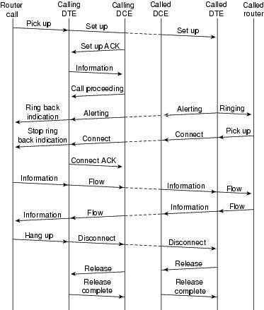
Two Layer 3 specifications are used for ISDN signaling: ITU-T (formerly CCITT) I.450 (also known as ITU-T Q.930) and ITU-T I.451 (also known as ITU-T Q.931). Together, these protocols support user-to-user, circuit-switched, and packet-switched connections. A variety of call establishment, call termination, information, and miscellaneous messages are specified, including SETUP, CONNECT, RELEASE, USER INFORMATION, CANCEL, STATUS, and DISCONNECT. These messages are functionally similar to those provided by the X.25 protocol (see Chapter 19, "Troubleshooting X.25 Connections," for more information). Figure 16-4, from ITU-T I.451, shows the typical stages of an ISDN circuit-switched call.
Figure 16-4 ISDN Circuit-Switched Call Stages
Interpreting show isdn status Output
To find out what the current condition of the ISDN connection is between the router and the telco switch, use the command show isdn status. The two kinds of interfaces that are supported by this command are the Basic Rate Interface (BRI) and the Primary Rate Interface (PRI) (Tables 16-5 and 16-6).
3620-2#show isdn statusGlobal ISDN Switchtype = basic-niISDN BRI0/0 interfacedsl 0, interface ISDN Switchtype = basic-niLayer 1 Status:ACTIVELayer 2 Status:TEI = 88, Ces = 1, SAPI = 0, State = MULTIPLE_FRAME_ESTABLISHEDTEI = 97, Ces = 2, SAPI = 0, State = MULTIPLE_FRAME_ESTABLISHEDSpid Status:TEI 88, ces = 1, state = 5(init)spid1 configured, no LDN, spid1 sent, spid1 validEndpoint ID Info: epsf = 0, usid = 0, tid = 1TEI 97, ces = 2, state = 5(init)spid2 configured, no LDN, spid2 sent, spid2 validEndpoint ID Info: epsf = 0, usid = 1, tid = 1Layer 3 Status:0 Active Layer 3 Call(s)Activated dsl 0 CCBs = 0The Free Channel Mask: 0x800000035200-1# show isdn statusGlobal ISDN Switchtype = primary-5essISDN Serial0:23 interfacedsl 0, interface ISDN Switchtype = primary-5essLayer 1 Status:ACTIVELayer 2 Status:TEI = 0, Ces = 1, SAPI = 0, State = MULTIPLE_FRAME_ESTABLISHEDLayer 3 Status:0 Active Layer 3 Call(s)Activated dsl 0 CCBs = 0The Free Channel Mask: 0x807FFFFFTotal Allocated ISDN CCBs = 05200-1#If the show isdn status command does not work or does not show the PRI, try using the show isdn service command. Make sure that the pri-group command appears in the configuration under the T1/E1 controller in the configuration. If the command is not present, configure the controller with the pri-group command.
Following is an example of a configuration for a Cisco router with a channelized T1 card:
controller t1 0framing esfline code b8zspri-group timeslots 1-24Table 16-6 details the fields for the show isdn status command.
Dial-on-Demand Routing: Dialer Interface Operations
Dial-on-demand routing (DDR) is a method of providing WAN connectivity on an economical as-needed basis, either as a primary link or as backup for a nondial serial link.
A dialer interface is defined as any router interface capable of placing or receiving a call. This generic term should be distinguished from the term Dialer interface (with a capital D), which refers to a logical interface configured to control one or more physical interfaces of a router and which is seen in a router configuration as interface Dialer X. From this point forward, unless otherwise stated, we will be using the term dialer in its generic sense.
Dialer interface configuration comes in two flavors: dialer map-based (sometimes referred to as legacy DDR) and dialer profiles. Which method you use depends on the circumstances under which you need dial connectivity. Dialer map-based DDR was first introduced in IOS version 9.0, and dialer profiles were introduced in IOS version 11.2.
Triggering a Dial
At its heart, DDR is just an extension of routing wherein interesting packets are routed to a dialer interface, triggering a dial attempt. We will attempt here to explain the concepts involved in defining interesting traffic, and to explain the routing used for DDR connections.
Interesting Packets
Interesting is the term used to describe packets or traffic that either will trigger a dial attempt or, if a dial link is already active, will reset the idle timer on the dialer interface. For a packet to be considered interesting, it must have these characteristics:
•
•
•
By default, no packets are considered to be interesting. Interesting packet definitions must be explicitly declared in a router or access server configuration.
Dialer Group
In the configuration of each dialer interface on the router or access server, there must be a dialer-group command. If the dialer-group command is not present, there is no logical link between the interesting packet definitions and the interface. The command syntax is as follows:
dialer-group [group number]
The group-number is the number of the dialer access group to which the specific interface belongs. This access group is defined with the dialer-list command. Acceptable values are nonzero, positive integers between 1 and 10.
An interface can be associated with a single dialer access group only; multiple dialer-group assignment is not allowed. A second dialer access group assignment will override the first. A dialer access group is defined with the dialer-group command. The dialer-list command associates an access list with a dialer access group.
Packets that match the dialer group specified trigger a connection request.
The destination address of the packet is evaluated against the access list specified in the associated dialer-list command. If it passes, either a call is initiated (if no connection has already been established) or the idle timer is reset (if a call is currently connected).
Dialer List
The dialer-list global configuration command is used to define a DDR dialer list to control dialing by protocol, or by a combination of protocol and access list. Interesting packets are those that match the protocol level permit or which are permitted by the list in the dialer-list command:
dialer-list dialer-group protocol protocol-name {permit | deny | list access-list-number | access-group}
•
•
•
•
•
•
•
Access List
For each networking protocol that is to be sent across the dial connection, an access list may be configured. For purposes of cost control, it is usually desirable to configure an access list to prevent certain traffic—such as routing updates—from bringing up or keeping up a connection. Note that when we create access lists for the purpose of defining interesting and uninteresting traffic, we are not declaring that uninteresting packets cannot cross the dial link—only that they will not reset the idle timer, nor will they bring up a connection on their own. As long as the dial connection is up, uninteresting packets will still be allowed to flow across the link.
For example, a router running EIGRP as its routing protocol can have an access list configured to declare EIGRP packets uninteresting and all other IP traffic interesting:
access-list 101 deny eigrp any any
access-list 101 permit ip any any
Access lists can be configured for all protocols that might cross the dial link. Remember that for any protocol, the default behavior in the absence of an access list permit statement is to deny all traffic. If there is no access list and if there is no dialer-list command permitting the protocol, then that protocol will be uninteresting. In actual practice, if there is no dialer list for a protocol, those packets will not flow across the link at all.
Example: Putting It All Together
With all the elements in place, it is possible to examine the complete process by which the "interesting" status of a packet is determined. In this example, IP and IPX are the protocols that may cross the dial link, but the user wants to prevent broadcasts and routing updates from initiating a call or keeping the link up.
!interface async 1dialer-group 7!access-list 121 deny eigrp any anyaccess-list 121 deny ip any host 255.255.255.255access-list 121 permit ip any anyaccess-list 903 deny -1 FFFFFFFF 0 FFFFFFFF 452access-list 903 deny -1 FFFFFFFF 0 FFFFFFFF 453access-list 903 deny -1 FFFFFFFF 0 FFFFFFFF 457access-list 903 permit -1!dialer-list 7 protocol ip list 121dialer-list 7 protocol ipx list 903!If a packet to be considered interesting when sent across interface async 1, it must first be permitted by the access-list 121 statements. In this case, EIGRP packets are denied, as are any other broadcast packets, while all other IP traffic is permitted. Remember that this does not prevent EIGRP packets from transiting the link—only that they will not reset the idle timer or initiate a dial attempt.
Similarly, access-list 903 declares IPX RIP, SAPs, and GNS requests to be uninteresting, while all other IPX traffic is interesting. Without these deny statements, the dial connection would likely never come down and a very large phone bill would result because packets of these types constantly flow across an IPX network.
With dialer-group 7 configured on the async interface, we know that dialer-list 7 is needed to tie the interesting traffic filters (that is, access lists) to the interface. One dialer-list statement is required (and only one can be configured) for each protocol, making sure that the dialer list number is the same as the dialer group number on the interface.
Again, it is important to remember that deny statements in the access lists configured for defining interesting traffic will not prevent the denied packets from crossing the link.
Using the command debug dialer, you can see the activity that triggers a dial attempt:
Dialing cause: Async1: ip (s=172.16.1.111 d=172.16.2.22)
Here we see that IP traffic with a source address of 172.16.1.111 and a destination address of 172.16.2.22 has triggered a dial attempt on interface Async1.
Routing
Now that interesting packets have been defined, they must be routed properly for a call to be initiated. The routing process depends on two things: routing table entries, and an "up" interface to which to route packets.
Interfaces—up/up (Spoofing)
For packets to be routed to and through and interface, that interface must be up/up, as seen in a show interfaces output:
Montecito# show interfaces ethernet 0
Ethernet0 is up, line protocol is up
Hardware is Lance, address is . . .
What about a dialer interface that is not connected? If the protocol is not up and running on the interface, the implication is that the interface itself will not be up; routes that rely on that interface will be flushed from the routing table, and traffic will not be routed to that interface. The result would be that no calls would be initiated by the interface.
To counter this possibility, any interface that is configured as a dialer interface (for example, a Serial or Async interface with the command dialer in-band or dialer dtr) or that, by its nature, is a dialer interface (BRIs and PRIs), will be in a state of up/up (spoofing):
Montecito# show interfaces bri 0
BRI0 is up, line protocol is up (spoofing)
Hardware is BRI
Internet address is . . .
In other words, the interface pretends to be up/up so that associated routes will remain in force and so that packets can be routed to the interface.
In some circumstances, a dialer interface will not be up/up (spoofing). The show interface output may show it as being administratively down:
Montecito# show interfaces bri 0BRI0 is administratively down, line protocol is downHardware is BRIInternet address is . . .Administratively down merely means that the interface has been configured with the command shutdown. This is the default state of any router interface when the router is booted for the very first time. To remedy this, use the interface configuration command no shutdown.
The interface may also be seen to be in standby mode:
Montecito# show interfaces bri 0
BRI0 is standby mode, line protocol is down
Hardware is BRI
Internet address is . . .
This state indicates that the interface has been configured as the backup for another interface. When a connection requires redundancy in case of failure, a dialer interface can be set up as the backup. This is accomplished by adding the following commands to the primary connection's interface:
backup interface [interface]
backup delay [enable-delay] [disable-delay]
After the backup interface command has been configured, the interface used as the backup will be put into standby mode until the primary interface goes to a state of down/down. At that time, the dialer interface configured as a backup will go to a state of up/up (spoofing) pending a dial event.
Static Routes and Floating Static Routes
The surest way to route packets to a dialer interface is with static routing. These routes are manually entered into the configuration of the router or access server with this command:
ip route prefix mask {address | interface} [distance]
•
•
•
•
•
Static routes are used in situations in which the dial link is the only connection to the remote site. A static route has an administrative distance value of 1, which makes it preferred over dynamic routes to the same destination.
On the other hand, floating static routes—that is, static routes with a predefined administrative distance—are typically used in backup DDR scenarios, in which a dynamic routing protocol such as RIP or EIGRP is used to route packets across the primary link. If a normal static route were to be used, its administrative distance of 1 would make it preferable to either EIGRP (75) or RIP (120), causing packets to be routed across the dial line even if the primary were up and capable of passing traffic. However, if the static route is configured with an administrative distance higher than that of any of the dynamic routing protocols in use on the router, the floating static route will be used only in the absence of a better route—one with a lower administrative distance.
If backup DDR is being invoked by use of the backup interface command, the situation is somewhat different. Because the dialer interface remains in standby mode while the primary is up, either a static route or a floating static route may be configured, and the dialer interface will not attempt to connect until after the primary interface goes down/down.
For a given connection, the number of static (or floating static) routes necessary is a function of the addressing on the dialer interfaces. In cases in which the two dialer interfaces (one on each of the two routers) share a common network or subnet, typically only one static route is required, pointing to the remote local-area network using the address of the remote router's dialer interface as the next-hop address.
Examples
Example 1:
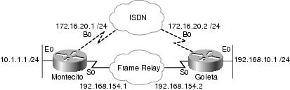
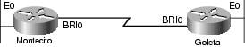
Dial is the only connection, with numbered interfaces, as shown in Figure 16-5. One route is sufficient.
Figure 16-5 Dial Using Numbered Interfaces
Montecito:
ip route 192.168.10.0 255.255.255.0 172.16.20.2
Goleta:
ip route 10.1.1.0 255.255.255.0 172.16.20.1
Example 2:
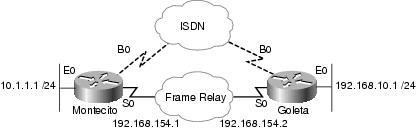
Dial is the only connection, with unnumbered interfaces, as shown in Figure 16-6. This can be configured with just one route, but it is common to configure two routes: a host route to the LAN interface on the remote router, and a route to the remote LAN via the remote LAN interface. This is done to prevent mapping problems from Layer 3 to Layer 2, which can result in encapsulation failures.
This method is also used if the dialer interfaces on the two devices are numbered, but not in the same network or subnet.
Figure 16-6 Dial Using Unnumbered Interfaces
Montecito:
ip route 192.168.10.0 255.255.255.0 192.168.10.1
ip route 192.168.10.1 255.255.255.255 BRI0
Goleta:
ip route 10.1.1.0 255.255.255.0 10.1.1.1
ip route 10.1.1.1 255.255.255.255 BRI0
Example 3:
Dial is a backup connection, using numbered interfaces, as shown in Figure 16-7. One floating static route is required.
Figure 16-7 Backup Using Numbered Interfaces
Montecito:
ip route 192.168.10.0 255.255.255.0 172.16.20.2 200
Goleta:
ip route 10.1.1.0 255.255.255.0 172.16.20.1 200
Example 4:
Dial is a backup connection using unnumbered interfaces, as shown in Figure 16-8. As in Example 2, this method is also used if the dialer interfaces on the two devices are numbered, but not in the same network or subnet.
Figure 16-8 Backup Using Unnumbered Interfaces
Montecito:
ip route 192.168.10.0 255.255.255.0 192.168.10.1 200
ip route 192.168.10.1 255.255.255.255 BRI0 200
Goleta:
ip route 10.1.1.0 255.255.255.0 10.1.1.1 200
ip route 10.1.1.1 255.255.255.255 BRI0 200
Dialer Maps
Dialer map-based (or legacy) DDR is powerful and comprehensive, but its limitations affect scaling and extensibility. Dialer map-based DDR is based on a static binding between the per-destination call specification and the physical interface configuration.
However, dialer map-based DDR also has many strengths. It supports Frame Relay, ISO CLNS, LAPB, snapshot routing, and all routed protocols that are supported on Cisco routers. By default, dialer map-based DDR supports fast switching.
When configuring an interface for outbound calling, one dialer map must be configured for each remote destination and for each different called number at the remote destination. For instance, if a multilink PPP connection is the goal when dialing from an ISDN BRI into another ISDN BRI interface that has a different local directory number for each of its B channels, one dialer map is needed for each of the remote numbers:
!interface bri 0dialer map ip 172.16.20.1 name Montecito broadcast 5551234dialer map ip 172.16.20.1 name Montecito broadcast 5554321!The order in which dialer maps are configured can be important. If two or more dialer map commands refer to the same remote address, the router or access server will try them one after another, in order, until a successful connection is established.
Note
Command Syntax
To configure a serial interface or an ISDN interface to call one or multiple sites, or to receive calls from multiple sites, use a form of the dialer map interface configuration command; all options are shown in the first form of the command. Table 16-8 lists the dialer map syntax descriptions. To delete a particular dialer map entry, use a no form of this command:
dialer map protocol next-hop-address [name hostname] [spc] [speed 56 | 64] [broadcast] [modem-script modem-regexp] [system-script system-regexp] [dial-string[:isdn-subaddress]]
To configure a serial interface or ISDN interface to place a call to multiple sites and to authenticate calls from multiple sites, use the second form of the dialer map command:
dialer map protocol next-hop-address [name hostname] [spc] [speed 56 | 64] [broadcast] [dial-string[:isdn-subaddress]]
To configure a serial interface or ISDN interface to support bridging, use the third form of the command:
dialer map bridge [name hostname] [spc] [broadcast] [dial-string[:isdn-subaddress]]
To configure an asynchronous interface to place a call to a single site that requires a system script or that has no assigned modem script, or to multiple sites on a single line, on multiple lines, or on a dialer rotary group, use the fourth form of the dialer map command:
dialer map protocol next-hop-address [name hostname] [broadcast] [modem-script modem-regexp] [system-script system-regexp] [dial-string]
Dialer Profiles
Note
The dialer profiles implementation of DDR, introduced in IOS version 11.2, is based on a separation between logical and physical interface configuration. Dialer profiles also enable the logical and physical configurations to be bound together dynamically on a per-call basis.
The dialer profiles methodology is advantageous when you want to share an interface (ISDN, asynchronous, or synchronous serial) to place or receive calls, when you want to change any configuration on a per-user basis (except encapsulation in the first phase of dialer profiles), when you want to bridge to many destinations, and for avoiding split horizon problems.
Dialer profiles allow the configuration of physical interfaces to be separated from the logical configuration required for a call, and they also allow the logical and physical configurations to be bound together dynamically on a per-call basis.
A dialer profile consists of the following elements:
•
•
•
All calls going to or from the same destination subnetwork use the same dialer profile.
A dialer interface configuration includes all settings needed to reach a specific destination subnetwork (and any networks reached through it). Multiple dial strings can be specified for the same dialer interface, each dial string being associated with a different dialer map-class. The dialer map class defines all the characteristics for any call to the specified dial string. For example, the map class for one destination might specify a 56-kbps ISDN speed; the map class for a different destination might specify a 64-kbps ISDN speed.
Each dialer interface uses a dialer pool, a pool of physical interfaces ordered on the basis of the priority assigned to each physical interface. A physical interface can belong to multiple dialer pools, with contention being resolved by priority. ISDN BRI and PRI interfaces can set a limit on the minimum and maximum number of B channels reserved by any dialer pools. A channel reserved by a dialer pool remains idle until traffic is directed to the pool.
When dialer profiles are used to configure DDR, a physical interface has no configuration settings except encapsulation and the dialer pools to which the interface belongs.
Note
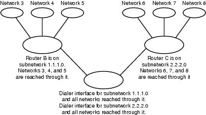
Figure 16-9 shows a typical application of dialer profiles. Router A has dialer interface 1 for dial-on-demand routing with subnetwork 1.1.1.0, and dialer interface 2 for dial-on-demand routing with subnetwork 2.2.2.0. The IP address for dialer interface 1 is its address as a node in network 1.1.1.0; at the same time, that IP address serves as the IP address of the physical interfaces used by the dialer interface 1. Similarly, the IP address for dialer interface 2 is its address as a node in network 2.2.2.0.
Figure 16-9 Typical Dialer Profiles Application
A dialer interface uses only one dialer pool. A physical interface, however, can be a member of one or many dialer pools, and a dialer pool can have several physical interfaces as members.
Figure 16-10 illustrates the relationships among the concepts of dialer interface, dialer pool, and physical interfaces. Dialer interface 0 uses dialer pool 2. Physical interface BRI 1 belongs to dialer pool 2 and has a specific priority in the pool. Physical interface BRI 2 also belongs to dialer pool 2. Because contention is resolved on the basis of priority levels of the physical interfaces in the pool, BRI 1 and BRI 2 must be assigned different priorities in the pool. Perhaps BRI 1 is assigned priority 100, and BRI 2 is assigned priority 50 in dialer pool 2 (a priority of 50 is higher than a priority of 100). BRI 2 has a higher priority in the pool, and its calls will be placed first.
Figure 16-10 Relationships Among Dialer Interfaces, Dialer Pools, and Physical Interfaces
Dialer profile configuration steps:
PPP Operations
The Point-to-Point Protocol (PPP) is by far the most common link-layer transport protocol, having completely usurped SLIP as the protocol of choice for dial (and, in many cases, nondial) synchronous and asynchronous serial connections. PPP was originally defined in 1989 by Request For Comments 1134 (RFC 1134), which has since been made obsolete by a series of RFCs culminating (as of this writing) in RFC 1661. Numerous RFCs also define elements of the protocol, such as RFC 1990 ("The PPP Multilink Protocol"), RFC 2125 ("The PPP Bandwidth Allocation Protocol"), and many others. An online repository of RFCs can be found at ftp://ftp.cisco.com/pub/rfc/RFC/.
Perhaps the best definition of just what PPP is can be found in RFC 1661, which states:
•
1.
2.
3.
Phases of PPP Negotiation
PPP negotiation consists of three phases: Link Control Protocol (LCP), authentication, and Network Control Protocol (NCP). Each proceeds in order following the establishment of the async or ISDN connection.
Link Control Protocol
PPP does not follow a client/server model—all connections are peer-to-peer so that, although there is a caller and a receiver, both ends of the point-to-point connection must agree on the negotiated protocols and parameters.
When negotiation begins, each of the peers that want to establish a PPP connection must send a configure request (seen in debug ppp negotiation and referred to hereafter as CONFREQ). Included in the CONFREQ are any options that are not the link default; these often include Maximum Receive Unit, Async Control Character Map, Authentication Protocol, and the Magic Number. Also seen often are the options that deal with multilink PPP.
There are three possible responses to any CONFREQ:
•
•
•
The two peers will continue to exchange CONFREQs, CONFREJs, and CONFNAKs until each sends a CONFACK, until the dial connection is broken, or until one or both of the peers deems the negotiation to be not completable.
Authentication
With LCP negotiation successfully completed, and an AUTHTYPE agreed upon, the next step is authentication. Authentication, while not mandatory per RFC 1661, is highly recommended on all dial connections; in some instances, it is a requirement for proper operation, with dialer profiles being a case in point.
The two principal types of authentication in PPP are the Password Authentication Protocol (PAP) and the Challenge Handshake Authentication Protocol (CHAP), defined by RFC 1334 and updated by RFC 1994. PAP is the simpler of the two, but it is less secure because the plain-text password is sent across the dial connection. CHAP, on the other hand, is more secure because the plain-text password is not ever sent across the dial connection.
This leads to a good question: Why should PAP ever be used? Two reasons frequently seen by Cisco TAC engineers are these:
•
•
When discussing authentication, it is helpful to use the terms requester and authenticator to distinguish the roles played by the devices at either end of the connection, although either peer can act in either role. Requester describes the device that requests network access and supplies authentication information; the authenticator verifies the validity of the authentication information and either allows or disallows the connection. It is common for both peers to act in both roles when a DDR connection is being made between routers.
PAP
PAP is fairly simple. After successful completion of the LCP negotiation, the requester repeatedly sends its username/password combination across the link until the authenticator responds with an acknowledgment or until the link is broken. The authenticator may disconnect the link if it determines that the username/password combination is not valid.
CHAP
CHAP is somewhat more complicated. The authenticator sends a challenge to the requester, which then responds with a value. This value is calculated by using a "one-way hash" function to hash the challenge and the CHAP password together. The resulting value is sent to the authenticator along with the requester's CHAP host name (which may be different from its actual host name) in a response message.
The authenticator reads the host name in the response message, looks up the expected password for that host name, and then calculates the value that it ought to expect the requester to have sent in its response by performing the same hash function that the requester performed. If the resulting values match, the authentication is successful. Failure should lead to a disconnect.
AAA
As part of authentication, use may be made of an authentication, authorization, and accounting (AAA, or triple-A) service such as TACACS+ or RADIUS. AAA is not a replacement for PAP or CHAP, but it is a mechanism for accomplishing them.
Network Control Protocol
Assuming successful authentication, the NCP phase begins. As in LCP, the peers exchange CONFREQs, CONFREJs, CONFNAKs, and CONFACKs, although in this phase of negotiation, the elements being negotiated have to do with higher-layer protocols—IP, IPX, bridging, CDP, and so on. One or more of these protocols may be negotiated. Because it is the most commonly used, and because other protocols operate in much the same fashion, Internet Protocol Control Protocol (IPCP), defined in RFC 1332, will be the focus of this discussion. Other pertinent RFCs include (but are not limited to) the following:
•
•
•
•
•
In addition, Cisco Discovery Protocol Control Protocol (CDPCP) may be negotiated during NCP, although this is not common—many Cisco TAC engineers advise that the command no cdp enable be configured on any and all dialer interfaces to prevent CDP packets from keeping a call up indefinitely.
The key element negotiated in IPCP is each peer's address. Each of the peers is in one of two possible states: either it has an IP address, or it does not.2 If the peer already has an address, it will send that address in a CONFREQ to the other peer. If the address is acceptable to the other peer, a CONFACK will be returned. If the address is not acceptable, the reply will be a CONFNAK containing an address for the peer to use.
If the peer has no address, it will send a CONFREQ with the address 0.0.0.0—this tells the other peer to assign an address, which is accomplished by sending a CONFNAK with the proper address.
Other options may be negotiated in IPCP. Commonly seen are the primary and secondary addresses for Domain Name Server and NetBIOS Name Server, as described in informational RFC 1877. Also commonly seen is the IP Compression Protocol (RFC 1332).
Alternate PPP Methodologies
PPP offers great flexibility in the manner in which it can be used. The following methodologies describe how to connect multiple links between two or more devices, and how to scale PPP for large numbers of inbound connections.
Multilink PPP
The Multilink Point-to-Point Protocol (MLP) feature provides load-balancing functionality over multiple WAN links, while providing multivendor interoperability, packet fragmentation and proper sequencing, and load calculation on both inbound and outbound traffic. Cisco's implementation of multilink PPP supports the fragmentation and packet sequencing specifications in RFC 1717.
Multilink PPP allows packets to be fragmented and for the fragments to be sent at the same time over multiple point-to-point links to the same remote address. The multiple links come up in response to a dialer load threshold that you define. The load can be calculated on inbound traffic, outbound traffic, or either, as needed for the traffic between the specific sites. MLP provides bandwidth on demand and reduces transmission latency across WAN links.
Multilink PPP is designed to work over single or multiple interfaces of the following types that are configured to support both dial-on-demand rotary groups and PPP encapsulation:
•
•
•
Configuration
To configure multilink PPP on asynchronous interfaces, you configure the asynchronous interfaces to support DDR and PPP encapsulation, and then you configure a dialer interface to support PPP encapsulation, bandwidth on demand, and multilink PPP. At some point, however, adding more asynchronous interfaces does not improve performance, With the default MTU size, multilink PPP should support three asynchronous interfaces using V.34 modems. However, packets might be dropped occasionally if the MTU is small or large bursts of short frames occur.
To enable multilink PPP on a single ISDN BRI or PRI interface, you are not required to define a dialer rotary group separately because ISDN interfaces are dialer rotary groups, by default. If you do not use PPP authentication procedures, your telephone service must pass caller ID information.
A load threshold number is required. For an example of configuring multilink PPP on a single ISDN BRI interface, see the next section, "Example of Multilink PPP on One ISDN Interface."
When multilink PPP is configured, and if you want a multilink bundle to be connected indefinitely, use the dialer idle-timeout command to set a very high idle timer. (The dialer-load threshold 1 command does not keep a multilink bundle of n links connected indefinitely, and the dialer-load threshold 2 command does not keep a multilink bundle of two links connected indefinitely.)
To enable multilink PPP on multiple ISDN BRI or PRI interfaces, you set up a dialer rotary interface and configure it for multilink PPP. Then you configure the BRIs separately and add them each to the same rotary group. See the "Example of Multilink PPP on Multiple ISDN Interfaces," next.
Example of Multilink PPP on One ISDN Interface
The following example enables multilink PPP on the BRI interface 0. Because an ISDN interface is a rotary group by default, when one BRI is configured, no dialer rotary group configuration is required.
interface bri 0ip address 171.1.1.7 255.255.255.0encapsulation pppdialer idle-timeout 30dialer load-threshold 40 eitherdialer map ip 172.16.20.2 name Goleta 5551212dialer-group 1ppp authentication papppp multilinkExample of Multilink PPP on Multiple ISDN Interfaces
The following example configures multiple ISDN BRIs to belong to the same dialer rotary group for multilink PPP. The dialer rotary-group command is used to assign each of the ISDN BRIs to that dialer rotary group—number 0, in this case—which must match the number of the dialer interface.
interface BRI0no ip addressencapsulation pppdialer rotary-group 0!interface BRI1no ip addressencapsulation pppdialer rotary-group 0!interface Dialer0ip address 172.16.20.1 255.255.255.0encapsulation pppdialer in-banddialer idle-timeout 500dialer map ip 172.16.20.2 name Goleta broadcast 5551212dialer load-threshold 30 eitherdialer-group 1ppp authentication chapppp multilinkMultichassis Multilink PPP
Multilink PPP provides the capability of splitting and recombining packets to a single end system across a logical pipe (also called a bundle) formed by multiple links. Multilink PPP provides bandwidth on demand and reduces transmission latency across WAN links.
Multichassis multilink PPP (MMP), on the other hand, provides the additional capability for links to terminate at multiple routers with different remote addresses. MMP can also handle both analog and digital traffic.
This functionality is intended for situations in which there are large pools of dial-in users, where a single access server cannot provide enough dial-in ports. MMP allows companies to provide a single dialup number to its users and to apply the same solution to analog and digital calls. This feature enables Internet service providers, for example, to allocate a single ISDN rotary number to several ISDN PRIs across several routers.
For a complete description of the MMP commands referenced herein, refer to the Cisco Dial Solutions Command Reference. To locate documentation of other commands that appear in this chapter, use the command reference master index or search online.
MMP is supported on the Cisco 7500, 4500, and 2500 series platforms, and on synchronous serial, asynchronous serial, ISDN BRI, ISDN PRI, and dialer interfaces.
MMP does not require reconfiguration of telephone company switches.
Configuration
Routers or access servers are configured to belong to groups of peers, called stack groups. All members of the stack group are peers; stack groups do not need a permanent lead router. Any stack group member can answer calls coming from a single access number, which is usually an ISDN PRI hunt group. Calls can come in from remote user devices, such as routers, modems, ISDN terminal adapters, or PC cards.
When a connection is established with one member of a stack group, that member owns the call. If a second call comes in from the same client and a different router answers the call, the router establishes a tunnel and forwards all packets belonging to the call to the router that owns the call. Establishing a tunnel and forwarding calls through it to the router that owns the call is sometimes called projecting the PPP link to the call master.
If a more powerful router is available, it can be configured as a member of the stack group, and the other stack group members can establish tunnels and forward all calls to it. In such a case, the other stack group members are just answering calls and forwarding traffic to the more powerful offload router.
Note
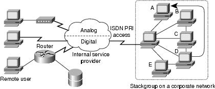
MMP call handling, bidding, and Layer 2 forwarding operations in the stack group proceed as follows, as shown in Figure 16-11:
1.
2.
3.
4.
5.
6.
7.
8.
9.
Figure 16-11 Typical Multichassis Multilink PPP Scenario
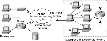
In contrast to the previous figure, Figure 16-12 features an offload router. Access servers that belong to a stack group answer calls, establish tunnels, and forward calls to a Cisco 4700 router that wins the bidding and is the call master for all the calls. The Cisco 4700 reassembles and resequences all the packets coming in through the stack group.
Figure 16-12 Multichassis Multilink PPP with an Offload Router as a Stack Group Member
Note
MMP support on a group of routers requires that each router be configured to support the following:
•
•
•
Virtual Profiles
Virtual Profiles is a unique Point-to-Point Protocol (PPP) application that can create and configure a virtual access interface dynamically when a dial-in call is received, and can tear down the interface dynamically when the call ends. Virtual Profiles works with straightforward PPP and with multilink PPP (MLP).
The configuration information for a Virtual Profiles virtual access interface can come from a virtual template interface or from user-specific configuration stored on an authentication, authorization, and accounting (AAA) server, or both.
The user-specific AAA configuration used by Virtual Profiles is interface configuration and is downloaded during LCP negotiations. Another feature, called per-user configuration, also uses configuration information gained from a AAA server. However, per-user configuration uses network configuration (such as access lists and route filters) downloaded during NCP negotiations.
Two rules govern virtual access interface configuration by Virtual Profiles virtual template interfaces and AAA configurations:
•
•
This feature runs on all Cisco IOS platforms that support MLP.
For a complete description of the commands mentioned in this section, refer to the "Virtual Profiles Commands" chapter in the Dial Solutions Command Reference in the Cisco IOS documentation set. To locate documentation of other commands that appear in this chapter, you can use the command reference master index or search online.
Background Information
This section presents background information about Virtual Profiles to help you understand this application before you start to configure it.
•
•
cisco-avpair = "lcp:interface-config=...",
The information that follows the equals sign (=), could be any Cisco IOS interface configuration command. For example, the line might be the following:
cisco-avpair = "lcp:interface-config=ip address 200.200.200.200 255.255.255.0",
Use of a virtual template interface with Virtual Profiles requires a virtual template to be defined specifically for Virtual Profiles.
•
DDR Configuration of Physical Interfaces
Virtual Profiles fully interoperates with physical interfaces in the following DDR configuration states when no other virtual access interface application is configured:
•
•
•
Note
Multilink PPP Effect on Virtual Access Interface Configuration
As shown in Table 16-9, exactly how a virtual access interface will be configured depends three factors:
•
•
•
In Table 16-9, "(Multilink VT)" means that a virtual template interface is cloned if one is defined for MLP or a virtual access feature that uses MLP.
Table 16-9 Virtual Profiles Configuration Cloning Sequence
ConfigurationVP VT only
VP VT
VP VT
VP VT
VP VT
VP AAA only
(Multilink VT)
VP AAA(Multilink VT)
VP AAAVP AAA
VP AAA
VP VT and VP AAA
VP VT
VP AAAVP VT
VP AAAVP VT
VP AAAVP VT
VP AAANo VP at all
(Multilink VT)1
Dialer2
No virtual access interface is created.
No virtual access interface is created.
1 The Multilink bundle virtual access interface is created and uses the default settings for MLP or the relevant virtual access feature that uses MLP.
2 The Multilink bundle virtual access interface is created and cloned from the dialer interface configuration.
The order of items in any cell of the table is important. Where VP VT is shown above VP AAA, it means that first the Virtual Profiles virtual template is cloned on the interface, and then the AAA interface configuration for the user is applied to it. The user-specific AAA interface configuration adds to the configuration and overrides any conflicting physical interface or virtual template configuration commands.
Interoperability with Other Features That Use Virtual Templates (Q10)
Virtual Profiles also interoperates with virtual access applications that clone a virtual template interface. Each virtual access application can have at most one template to clone from, but it can clone from multiple AAA configurations.
The interaction between Virtual Profiles and other virtual template applications is as follows:
•
•
•
Terminology
The following new or uncommon terms are used here:
•
An interface configuration AV pair for Virtual Profiles can take a form such as this:
cisco-avpair = "lcp:interface-config=ip address 1.1.1.1 255.255.255.255.0",
•
•
•
•
Configuration of a virtual access interface begins with a virtual template interface (if any), followed by application of user-specific configuration for the particular user's dial-in session (if any).
Annotated Example of PPP Negotiation
In Figure 16-13, a ping brings up an ISDN link between routers Montecito and Goleta. Note that although there is no timestamping in this example, it is usually recommended that you use the global configuration command service timestamps debug datetime msec.
Figure 16-13 Router-ISDN-Router
These debugs are taken from Montecito; the debugging on Goleta would look much the same.
Note
Example 16-2 shows the debug and ping information for the ISDN link between Montecito and Goleta.
A—Traffic is generated in order to initiate a dial attempt.
B—The connection is established (ISDN debugs are not used in this example).
Begin LCP:
C—Montecito sends LCP configuration requests for AUTHTYPE and for MAGICNUMBER.
D— Goleta sends its CONFREQs. If the value for MAGICNUMBER is the same as the value sent by Montecito, there is a strong probability that the line is looped.
E—This indicates that Montecito has sent acknowledgments to Goleta's CONFREQs.
F—Montecito receives CONFACKs from Goleta.
Begin authentication phase:
G, H—Montecito and Goleta challenge each other for authentication.
J— Goleta responds to the challenge.
K, L— Goleta successfully passes authentication.
M— Goleta sends a message to Montecito, saying that authentication was successful.
NCP negotiation begins:
N, P—Each router sends its configured IP address in a CONFREQ.
Q, R—Montecito sends a CONFACK to Goleta's CONFREQ . . .
S— . . . and vice versa.
T, U—A route is installed from Montecito to Goleta, and the protocol on the interface changes to "up," indicating that the NCP negotiations have completed successfully.
Before Calling Cisco Systems's TAC Team
Before calling Cisco Systems's Technical Assistance Center (TAC), make sure that you have read through this chapter and completed the actions suggested for your system's problem.
Additionally, do the following and document the results so that we can better assist you:
For all problems, collect the output of show running-config and show version. Ensure that the command service timestamps debug datetime msec is in the configuration.
For DDR problems, collect the following:
•
•
•
•
If ISDN is involved, collect the following:
•
•
•
If modems are involved, collect the following:
•
•
•
•
•
•
•
If T1s or PRIs are involved, collect the following:
•
Additional Sources
•
•
1 Note that Cisco IOS does not support Bridging on asynchronous interfaces.
2 Interfaces configured using ip unnumbered [interface name] are considered to have an IP address. They use the IP address of the interface named in the configuration command.