Downloads |
 Feedback Feedback
|
Table Of Contents
Tools for Troubleshooting IP Problems
General IP Troubleshooting Suggestions
Narrowing Down the Problem Domain
Troubleshooting Local Connectivity Problems
Check for Configuration Problems
Ruling Out Duplicate IP Addresses
Troubleshooting Physical Connectivity Problems
Rule Out a Configuration Problem
Troubleshooting IP Connectivity and Routing Problems
Check for Network Address Translation
Troubleshooting Upper-Layer Problems
Troubleshooting Domain Name Server Problems
Before Calling Cisco Systems' Technical Assistance Center
Troubleshooting TCP/IP
The sections in this chapter describe common features of TCP/IP and provide solutions to some of the most common TCP/IP problems. The following items will be covered:
•
TCP/IP Introduction
•
•
•
•
•
•
TCP/IP Introduction
In the mid-1970s, the Defense Advanced Research Projects Agency (DARPA) became interested in establishing a packet-switched network to provide communications between research institutions in the United States. DARPA and other government organizations understood the potential of packet-switched technology and were just beginning to face the problem that virtually all companies with networks now have—communication between dissimilar computer systems.
With the goal of heterogeneous connectivity in mind, DARPA funded research by Stanford University and Bolt, Beranek, and Newman (BBN) to create a series of communication protocols. The result of this development effort, completed in the late 1970s, was the Internet Protocol suite, of which the Transmission Control Protocol (TCP) and the Internet Protocol (IP) are the two best-known protocols.
The most widespread implementation of TCP/IP is IPv4 (or IP version 4). In 1995, a new standard, RFC 1883—which addressed some of the problems with IPv4, including address space limitations—was proposed. This new version is called IPv6. Although a lot of work has gone into developing IPv6, no wide-scale deployment has occurred; because of this, IPv6 has been excluded from this text.
Internet Protocols
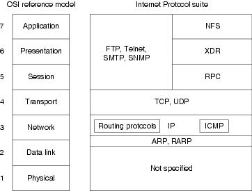
Internet protocols can be used to communicate across any set of interconnected networks. They are equally well suited for local-area network (LAN) and wide-area network (WAN) communications. The Internet suite includes not only lower-layer specifications (such as TCP and IP), but also specifications for such common applications as e-mail, terminal emulation, and file transfer. Figure 7-1 shows some of the most important Internet protocols and their relationships to the OSI reference model.
As an interesting side note, the seven-layer model actually came about after TCP/IP. DARPA used a four-layer model instead, which the OSI later expanded to seven layers. This is why TCP/IP doesn't generally fit all that well into the seven-layer OSI model.
Figure 7-1 The Internet Protocol Suite and the OSI Reference Model
Creation and documentation of the Internet Protocol suite closely resemble an academic research project. The protocols are specified and refined in documents called Requests For Comments (RFCs), which are published, reviewed, and analyzed by the Internet community. Taken together, the RFCs provide a colorful history of the people, companies, and trends that have shaped the development of what is today the world's most popular open-system protocol suite.
The Network Layer
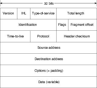
IP is the primary Layer 3 protocol in the TCP/IP suite. IP provides the logical addressing that enables communication across diverse networks. IP also provides fragmentation and reassembly of datagrams and error reporting. Along with TCP, IP represents the heart of the Internet Protocol suite. The IP packet format is shown in Figure 7-2.
Figure 7-2 The IP Packet Format
The fields of the IP packet are as follows:
•
•
•
Today this field is used primarily to provide quality of service (QoS) capabilities to TCP/IP for applications requiring predictable bandwidth or delay. RFC 2474 describes a method by which the TOS field is replaced by a DS field that is used to provide differentiated services (DiffServ) on networks. This field is split into two parts. The first 6 bits are used for the DSCP codepoint, which is used to differentiate traffic. The last 2 bits, or CU, are ignored by DiffServ-compliant nodes.
•
•
•
•
•
•
•
•
•
•
Addressing
As with all network layer protocols, the addressing scheme is integral to the process of routing IP datagrams through an internetwork. An IP address is 32 bits in length, divided into either two or three parts. The first part designates the network address, the second part (if present) designates the subnet address, and the final part designates the host address. Subnet addresses are present only if the network administrator has decided that the network should be divided into subnetworks. The lengths of the network, subnet, and host fields are all variable.
Today's Internet does not segment addresses along classful bounds—it is almost entirely classless. The separation between networks and subnets has been effectively eliminated. The requirement to understand network classes and the difference between a network and a subnet remains solely because of configuration and behavioral issues with network devices.
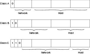
IP addressing supports five different network classes, and the high-order—far-left—bits indicate the network class:
•
•
•
•
•
IP addresses are written in dotted decimal format (for example, 34.10.2.1). Figure 7-3 shows the address formats for Class A, B, and C IP networks.
Figure 7-3 Class A, B, and C Address Formats
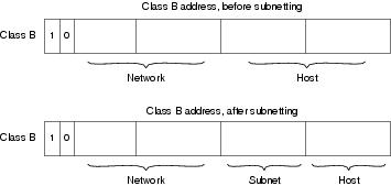
IP networks can also be divided into smaller units called subnets. Subnets provide extra flexibility for network administrators. For example, assume that a network has been assigned a Class B address, and all the nodes on the network currently conform to a Class B address format. Then assume that the dotted decimal representation of this network's address is 172.16.0.0 (all zeros in the Host field of an address specifies the entire network). Rather than change all the addresses to some other basic network number, the administrator can subdivide the network using subnetting. This is done by borrowing bits from the host portion of the address and using them as a subnet field, as shown in Figure 7-4.
Figure 7-4 Subnet Addresses
If a network administrator has chosen to use 8 bits of subnetting, the third octet of a Class B IP address provides the subnet number. For example, address 172.16.1.0 refers to network 172.16, subnet 1; address 172.16.2.0 refers to network 172.16, subnet 2; and so on. In today's world, the difference between subnet bits and the natural mask has become blurred, and you will often see only a prefix length that specifies the length of the entire mask (natural mask plus subnet bits). It is still important to understand the difference between the natural network mask, which is determined by the network class, and the subnet mask, because routers sometimes make assumptions based on the natural mask of an address. For example, the natural mask of 10.1.1.1/24 is 8 bits because this is a class A network, even though the subnet mask is 24 bits.
Subnet masks can be expressed in two forms: prefix length (as in /24), or dotted-decimal notation (As in 255.255.255.0). Both forms mean exactly the same thing and can easily be converted to the other, as seen in Example 7-1.
Example 7-1 Subnet Mask Expressed in Prefix Length and Dotted Decimal
On some media (such as IEEE 802 LANs), the correlation between media addresses and IP addresses is dynamically discovered through the use of two other members of the Internet Protocol suite: the Address Resolution Protocol (ARP) and the Reverse Address Resolution Protocol (RARP). ARP uses broadcast messages to determine the hardware Media Access Control (MAC)-layer address corresponding to a particular IP address. ARP is sufficiently generic to allow use of IP with virtually any type of underlying media-access mechanism. RARP uses broadcast messages to determine the Internet address associated with a particular hardware address. RARP is particularly important to diskless nodes, which may not know their IP address when they boot.
Internet Routing
Routing devices in the Internet have traditionally been called gateways—an unfortunate term because elsewhere in the industry, the term gateway applies to a device with somewhat different functionality. Gateways (which we will call routers from this point on) within the Internet are organized hierarchically.
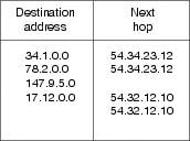
Dynamic routing protocols, such as RIP and OSPF, provide a means by which routers can communicate and share information about routes that they have learned or are connected to. This contrasts with static routing, in which routes are established by the network administrator and do not change unless they are manually altered. An IP routing table consists of destination address/next-hop pairs. A sample entry, shown in Figure 7-5, is interpreted as meaning, "To get to network 34.1.0.0 (subnet 1 on network 34), the next stop is the node at address 54.34.23.12."
Figure 7-5 An Example of an IP Routing Table
IP routing specifies that IP datagrams travel through internetworks one hop at a time; the entire route is not known at the outset of the journey. Instead, at each stop, the next destination is calculated by matching the destination address within the datagram with an entry in the current node's routing table. Each node's involvement in the routing process consists only of forwarding packets based on internal information, regardless of whether the packets get to their final destination. In other words, IP does not provide for error reporting back to the source when routing anomalies occur. This task is left to other Internet protocols, such as the Internet Control Message Protocol (ICMP) and TCP protocol.
ICMP
ICMP performs a number of tasks within an IP internetwork, the principal of which is reporting routing failures back to the source of a datagram. In addition, ICMP provides helpful messages such as the following:
•
•
•
•
The Transport Layer
The Internet transport layer is implemented by Transport Control Protocol (TCP) and the User Datagram Protocol (UDP). TCP provides connection-oriented data transport, whereas UDP operation is connectionless.
TCP
TCP provides full-duplex, acknowledged, and flow-controlled service to upper-layer protocols. It moves data in a continuous, unstructured byte stream in which bytes are identified by sequence numbers. TCP can support numerous simultaneous upper-layer conversations. The TCP packet format is shown in Figure 7-6.
Figure 7-6 The TCP Packet Format
The fields of the TCP packet are described here:
•
•
•
•
•
•
•
•
•
•
•
UDP
UDP is a much simpler protocol than TCP and is useful in situations in which the reliability mechanisms of TCP are not necessary. The UDP header has only four fields: Source Port, Destination Port, Length, and UDP Checksum. The Source and Destination Port fields serve the same functions as they do in the TCP header. The Length field specifies the length of the UDP header and data, and the UDP Checksum field allows packet integrity checking. The UDP checksum is optional.
Upper-Layer Protocols
The Internet Protocol suite includes many upper-layer protocols representing a wide variety of applications, including network management, file transfer, distributed file services, terminal emulation, and electronic mail. Table 7-1 maps the best-known Internet upper-layer protocols to the applications that they support.
These and other network applications use the services of TCP/IP and other lower-layer Internet protocols to provide users with basic network services.
Domain Name System
TCP/IP uses a numeric addressing scheme in which each node is assigned an IP address that is used to route packets to a node on the network. Because it is much easier for people to remember names such as www.somedomain.com instead of 10.1.1.1, a protocol called Domain Name System (DNS) is used to map numbers to names, and vice versa. Most web pages refer to other web pages or links using these names instead of their IP addresses. This provides many advantages; for example, the address can change without breaking any links to a web page if the DNS table is also changed to point to the new address.
Tools for Troubleshooting IP Problems
The tools ping and traceroute, both in the TCP/IP protocol suite, will greatly assist in troubleshooting IP connectivity. Most operating systems and IP implementations come with these tools installed by default. On some UNIX platforms, however, you may need to download and install a traceroute package.
Cisco routers provide a basic method of viewing IP traffic switched through the router called packet debugging. Packet debugging enables a user to determine whether traffic is travelling along an expected path in the network or whether there are errors in a particular TCP stream. Although in some cases packet debugging can eliminate the need for a packet analyzer, it should not be considered a replacement for this important tool.
Packet debugging can be very intrusive—in some cases, it can cause a router to become inoperable until physically reset. In other instances, packets that are present on the network and switched through the router may not be reported by packet debugging. Thus, a firm conclusion cannot be drawn that a packet was not sent solely from the output of packet debugging; a network analyzer must be used to accurately make this assessment. Packet debugging should be used with extreme caution by only advanced operators because it can cause the router to lock up and stop routing traffic, if not used carefully. The risks of using packet debugging may be compounded by the necessity of disabling fast switching for packet debugging to be effective. As a general rule, packet debugging should not be used on a production router unless you have physical access to the router and are willing to risk it going down.
ping
The ping tool uses the IP ICMP echo request and echo reply messages to test reachability to a remote system. In its simplest form, ping simply confirms that an IP packet is capable of getting to and getting back from a destination IP address (Figure 7-7). This tool generally returns two pieces of information: whether the source can reach the destination (and, by inference, vice versa), and the round-trip time (RTT, typically in milliseconds). The RTT returned by ping should be used only as a comparative reference because it can depend greatly on the software implementation and hardware of the system on which ping is run. If ping fails or returns an unusual RTT, traceroute can be used to help narrow down the problem. It is also possible to vary the size of the ICMP echo payload to test problems related to maximum transmission unit (MTU).
Figure 7-7 ping Example (pingfig.gif/cdr)
Example 7-2 shows ping returning three values separated with the slash "/," the minimum, average, and maximum RTT. Large differences in these values could indicate network congestion or a network problem. In most cases, the average value accurately portrays the network latency to the destination. By default, ping uses small packets for connectivity testing; the packet size will influence the RTT values. The packet size may be changed in some implementations, including that of Cisco Systems's IOS.
Firewalls and routers can be configured to not allow devices to be pinged but to still permit other types of IP traffic. For this reason, a ping failure between two devices should not be misconstrued as a lack of IP connectivity between those devices. Table 7-2 shows a list of some of the codes returned by the Cisco ping utility, along with their meanings and possible cause.
traceroute
The traceroute utility sends out either ICMP echo request (Windows) or UDP (most implementations) messages with gradually increasing IP TTL values to probe the path by which a packet traverses the network (see Example 7-3). The first packet with the TTL set to 1 will be discarded by the first hop, and the first hop will send back an ICMP TTL exceeded message sourced from its IP address facing the source of the packet. When the machine running the traceroute receives the ICMP TTL exceeded message, it can determine the hop via the source IP address. This continues until the destination is reached. The destination will return either an ICMP echo reply (Windows) or a ICMP port unreachable, indicating that the destination had been reached. Cisco's implementation of traceroute sends out three packets at each TTL value, allowing traceroute to report routers that have multiple equal-cost paths to the destination.
Traceroute can return useful information about TCP/IP connectivity across your network. Table 7-3 shows some of the codes that can be returned by the Cisco traceroute utility, along with their possible cause.
If there had been a problem between CiscoRtr5 and CiscoRtr6, you would have seen the following on a Cisco router:
CiscoRtr1>traceroute 10.3.1.6Type escape sequence to abort.Tracing the route to 10.3.1.61 CiscoRtr2 (10.1.1.2) 0 msecCiscoRtr3 (10.1.1.3) 0 msecCiscoRtr4 (10.1.1.4) 4 msec2 CiscoRtr5 (10.2.1.6) 4 msec 4 msec 0 msec3 * * *4 * * *Although it may also be possible to trace the path between source and destination using ping and the IP record route option, traceroute is preferred because the record route option can alter the way in which packets are forwarded by routers in the network, yielding incorrect path information.
Packet Debugging
The following example is applicable to Cisco 16xx, 25xx, 26xx, 36xx, 40xx, 45xx, 70xx, and 75xx series routers. Consult the Cisco TAC web page www.cisco.com/tac for instructions on using this command on other Cisco router platforms.
Caution
To use the debug ip packet command, you must do the following:
1.
CiscoRtr> enableCiscoRtr#2.
CiscoRtr# configure terminalCiscoRtr(config)# no logging consoleCiscoRtr(config)# endCiscoRtr#3.
CiscoRtr# configure terminalCiscoRtr(config)# logging bufferedCiscoRtr(config)# endCiscoRtr#4.
CiscoRtr# configure terminalCiscoRtr(config)# service timestamps log datetime msecCiscoRtr(config)# endCiscoRtr#5.
CiscoRtr#show processes cpuCPU utilization for five seconds: 2%/0%; one minute: 0%; five minutes: 0%PID Runtime(ms) Invoked uSecs 5Sec 1Min 5Min TTY Process1 2075 308386 6 0.00% 0.00% 0.00% 0 Load Meter2 273 55 4963 1.55% 0.18% 0.06% 0 Exec[snip]CiscoRtr#6.
CiscoRtr#configure terminalCiscoRtr(config)# interface ethernet 0CiscoRtr(config-if)# no ip route-cacheCiscoRtr(config-if)# interface ethernet 1CiscoRtr(config-if)# no ip route-cacheCiscoRtr(config-if)# endCiscoRtr#7.
CiscoRtr#configure terminalCiscoRtr(config)# access-list 101 permit udp any any eq bootpcCiscoRtr(config)# access-list 101 permit udp any any eq bootpsCiscoRtr(config)# access-list 101 permit udp any eq bootpc anyCiscoRtr(config)# access-list 101 permit udp any eq bootps anyCiscoRtr(config)# endCiscoRtr#8.
CiscoRtr# show ip access-listsExtended IP access list 101permit udp any any eq bootpcpermit udp any any eq bootpspermit udp any eq bootpc anypermit udp any eq bootps any9.
CiscoRtr# debug ip packet 101 detail10.
CiscoRtr# undebug all11.
CiscoRtr# show logSyslog logging: enabled (0 messages dropped, 0 flushes, 0 overruns)Console logging: disabledMonitor logging: level debugging, 0 messages loggedBuffer logging: level debugging, 16 messages loggedTrap logging: level informational, 0 message lines loggedLog Buffer (4096 bytes):*Mar 16 18:00:10.485: IP: s=0.0.0.0 (Ethernet0), d=255.255.255.255, len 328, rcvd 2*Mar 16 18:00:10.485: UDP src=68, dst=67*Mar 16 18:00:10.485: IP: s=10.1.1.1 (local), d=10.1.2.2 (Ethernet1), len 328, sending*Mar 16 18:00:10.485: UDP src=67, dst=67*Mar 16 18:00:10.492: IP: s=10.1.2.2 (Ethernet1), d=10.1.1.1, len 328, rcvd 4*Mar 16 18:00:10.492: UDP src=67, dst=67*Mar 16 18:00:10.492: IP: s=10.1.1.1 (local), d=10.1.1.10 (Ethernet0), len 328, sending*Mar 16 18:00:10.492: UDP src=67, dst=68*Mar 16 18:00:10.510: IP: s=0.0.0.0 (Ethernet0), d=255.255.255.255, len 328, rcvd 2*Mar 16 18:00:10.510: UDP src=68, dst=67*Mar 16 18:00:10.510: IP: s=10.1.1.1 (local), d=10.1.2.2 (Ethernet1), len 328, sending*Mar 16 18:00:10.510: UDP src=67, dst=67*Mar 16 18:00:10.530: IP: s=10.1.2.2 (Ethernet1), d=10.1.1.1, len 328, rcvd 4*Mar 16 18:00:10.530: UDP src=67, dst=67*Mar 16 18:00:10.530: IP: s=10.1.1.1 (local), d=10.1.1.10 (Ethernet0), len 328, sending*Mar 16 18:00:10.530: UDP src=67, dst=68General IP Troubleshooting Suggestions
This chapter approaches the process of troubleshooting TCP/IP connectivity issues with the assumption that you will have access to the client (or source) and may not have access to the server (or destination). If the problem is determined to be a server issue, you contact the server administrator. If you are the server administrator, you can apply the troubleshooting process in reverse (server to client) to further troubleshoot connectivity issues. This chapter will not address the specifics of troubleshooting server-side IP services; for this, consult the manual or web page for the software or service running on the server.
Because TCP/IP does not store path information in its packets, it is possible for a packet to have a working path from the source to the destination (or vice versa), but not to have a working path in the opposite direction. For this reason, it may be necessary to perform all troubleshooting steps in both directions along an IP path to determine the cause of a connectivity problem.
Narrowing Down the Problem Domain
To efficiently troubleshoot a TCP/IP connectivity problem, it is necessary to identify a single pair of source and destination devices that are exhibiting the connectivity problem. When you've selected the two devices, test to make sure that the problem is actually occurring between these two devices.
Possible problems include these:
•
•
•
•
Where to start:
1.
2.
3.
Troubleshooting Local Connectivity Problems
This section describes how to troubleshoot local connectivity problems on LAN segments such as Ethernet or Token Ring. Going through the methodology in this chapter with help determine and resolve problems moving packets on the local LAN segment or to the next-hop router. If the problem is determined to be past the local LAN segment, then you will be referred to the section "Troubleshooting IP Connectivity and Routing Problems," later in this chapter. If the source device is connected via a modem, then you should consult Chapter 16, "Troubleshooting Dialup Connections."
Possible problems include these:
•
•
•
•
Check for Configuration Problems
To begin troubleshooting, display and examine the IP configuration of the source device. The method to determine this information varies greatly from platform to platform. If you are unsure of how to display this information, consult the manual for the device or operating system. Refer to the following examples:
•
•
•
•
Examine the configuration, looking specifically for the IP address and subnet mask. On Windows 9x or Windows 2000 platforms, the default gateway address should also be displayed.
If no IP address is configured, verify that this node receives its IP address from BOOTP or DHCP. Otherwise, an IP address should be statically configured for this interface. Configure an address if one is not present. If the source is configured to receive an IP address via DHCP or BOOTP and is not receiving one, make sure that the bootp (IP) helper address is configured on the router interface facing the source device.
If the incorrect IP address, subnet mask, or default gateway is configured, verify that this node receives its IP address from BOOTP or DHCP, and then contact the DHCP or BOOTP administrator. Ask the administrator to troubleshoot the DHCP or BOOTP server's configuration. If the address is statically configured, configure the correct address.
Check for Local Connectivity
If the destination is on the same subnet as the source, try pinging the destination by IP address. If the destination is on a different subnet, then try pinging the default gateway or appropriate next hop obtained from the routing table. If the ping fails, double-check the configuration of the next-hop router to see if the subnet and mask match the source's configuration.
If the configuration is correct, check that the source or next-hop router is capable of pinging any other device on the local LAN segment. If you cannot ping the next-hop address, and if the next-hop address is an HSRP virtual address, try pinging one of the next-hop router's actual IP addresses. If the actual address works but the virtual address does not, you may be experiencing an HSRP issue. Failure to communicate with some or all devices on the LAN segment could indicate a physical connectivity problem, a switch or bridge misconfiguration, or a duplicate IP address.
Ruling Out Duplicate IP Addresses
To rule out a duplicate IP address, you can disconnect the suspect device from the LAN or shut down the suspect interface and then try pinging the device from another device on that same LAN segment. If the ping is successful, then there is another device on that LAN segment using the IP address. You will be able to determine the MAC address of the conflicting device by looking at the ARP table on the device that issued the ping.
If at this point you still do not have local connectivity for either the source or the next-hop router, proceed to the next section.
Troubleshooting Physical Connectivity Problems
This section describes how to troubleshoot Layer 1 and 2 physical connectivity issues on LANs such as Ethernet or Token Ring. For troubleshooting information on dialup links or WAN connections, consult the chapters in Part IV, "Troubleshooting Serial Lines and WAN Connections."
Even though it may seem logical to first troubleshoot at the physical layer, problems can generally be found more quickly by first troubleshooting at Layer 3 and then working backward when a physical problem is found or suspected.
Possible problems include these:
•
•
•
•
•
Rule Out a Configuration Problem
Check to make sure that all cables are connected to the appropriate ports. Make sure that all cross-connects are properly patched to the correct location using the appropriate cable and method. Verify that all switch or hub ports are set in the correct VLAN or collision domain and have appropriate options set for spanning tree and other considerations.
Check Cable Connections
Verify that the proper cable is being used. If this is a direct connection between two end systems (for example, a PC and a router) or between two switches, a special crossover cable may be required. Verify that the cable from the source interface is properly connected and is in good condition. If you doubt that the connection is good, reseat the cable and ensure that the connection is secure. Try replacing the cable with a known working cable. If this cable connects to a wall jack, use a cable tester to ensure that the jack is properly wired. Also check any transceiver in use to ensure that it is the correct type, is properly connected, and is properly configured. If replacing the cable does not resolve the problem, try replacing the transceiver if one is being used.
Check the Configuration
Verify that the interface on the device is configured properly and is not shut down. If the device is connected to a hub or switch, verify that the port on the hub or switch is configured properly and is not shut down. Check both speed and duplex.
Check the Network Interface
Most interfaces or NICs will have indicator lights that show whether there is a valid connection; often this light is called the link light. The interface may also have lights to indicate whether traffic is being sent (TX) or received (RX). If the interface has indicator lights that do not show a valid connection, power off the device and reseat the interface card.
Troubleshooting IP Connectivity and Routing Problems
When troubleshooting IP connectivity problems across large networks, it always helps to have a network diagram handy so that you can understand the path that the traffic should take and compare it to the path that it is actually taking.
When IP packets are routed across a network, there is the potential for problems at every hop between the source and the destination, so test connectivity at each hop to determine where it is broken is the logical troubleshooting methodology.
The following could be wrong:
•
•
•
•
•
•
•
•
Determining Where to Start
The most detailed method to find a problem would obviously be to start at the next hop away from the source and work your way one hop at a time toward the destination, exploring all possible paths along the way. You would then test basic IP connectivity and possibly protocol connectivity from each router forward. Although in some cases this method is the only one available, the process can generally be shortened by first performing a traceroute from the source to the destination to determine the first problematic hop. If the traceroute method does not provide an answer, you will have to fall back to the longer method.
When you have found a starting point, connect to that router via telnet or console, and verify that it is capable of pinging the source and the destination. When doing this, keep in mind that the router will source the ping packet from the interface closest to the ping target. In some cases, you may want to use an extended ping to specify a source interface because the ping target may not know how to get to the default source address; this is common on serial interfaces configured with private addressing.
Check for Resources
If the router appears sluggish or does not respond (echo) to what you are typing quickly, or if you suspect a resource issue, check the router's resources. Check memory using show memory; be sure not to have terminal length 0 configured when doing this, or it make take a long time. Look at how much memory is available in the largest free field. If this number is low (less than 5 percent of total router memory), use show process memory to identify which process(es) are "holding" the memory.
Sluggish router response can also be caused by CPU overload. This can be checked using show process cpu. You will see two percentages listed (such as 75%/24%). The first number is the total CPU utilization for the router, and the second is interrupt-generated processor utilization. If the total CPU utilization is greater than 90 percent for an extended period of time (10 to 15 minutes), then you should investigate what is using all the CPU. Show process cpu will show which processes are running and how much CPU they are using. If the CPU is too high, it is possible to lose console and Telnet access to the router.
Although I will not cover all the processes that could possibly be running, a few have special meaning. The IP Input process is tied to process-switched traffic. Some traffic that will frequently cause an increase in process-switched traffic includes broadcast traffic, multicast traffic, routing updates, or traffic destined for an IP address on the router. For example, a broadcast storm will cause IP Input to increase and can cause CPU to jump to 99 percent. You will also see processes for the individual routing protocols such as these:
•
•
•
If a routing protocol is converging, it is possible that one of these processes may increase CPU utilization; in most cases, this is normal.
Check for Connectivity
If you cannot ping from this router to either the source or the destination, check the routing table for a route to the ping target. Keep in mind that it may be desirable for the router to use the default route to this destination, and ip classless may need to be configured for this to happen. If there is no route to the ping target, you will need to either troubleshoot your routing protocol, if you are running one, or add a static route to the destination network. The router will need to have both a route to the source and to the destination for communication to succeed.
If ping succeeds only a percentage of the time, look to see if there are multiple paths to the destination. If there are multiple paths, it is possible that one path may be failing while the others are working. This can be symptomatic of a routing loop or physical problem somewhere along the path. The only way to test whether a path is failing is to go to all the next hops and test connectivity from there.
Pings with less than 100 percent success rate can also indicate problematic links or links with high utilization. Look at the interface statistics using show interface for outgoing interfaces to see if any have problems. When reviewing statistics, keep in mind that the router may have been collecting information for years; always look at the uptime for the router, reported in show version, and the last time that the counters were reset, reported at the top of show interface. Generally, the counters can be looked at as an accurate percentage of packets received or sent. If the counters have not been reset in a long time, or if a problem is suspected, the counters should be reset using clear counters command, and a new reading should be taken after a reasonable period of time has elapsed. If a problem is detected on a WAN or dialup link, refer to Part IV. If a problem is detected on a LAN connection, see the section "Troubleshooting Physical Connectivity Problems," earlier in this chapter.
Check for ACLs
Check this router for any access lists applied to an interface using ip access-group, or any other firewall or packet filters configured. Does the packet filtering permit the desired source/destination to communicate using the requested protocol? If you are unsure, see the section "Troubleshooting Upper-Layer Problems."
Check for Network Address Translation
Check to see if this router is configured for network address translation. If it is, is it supposed to translate packets between the source and destination? Has it been configured correctly?
At this point, you will want to move on to one of the next-hop routers. Record routers that you have already visited on a piece of paper. Also record any problems or questions that arose at the router. This record will help you detect routing loops and will provide useful information if you find it necessary to call for support.
Troubleshooting Upper-Layer Problems
Even though there may be IP connectivity between a source and a destination, problems may still exist for a specific upper-layer protocols such as FTP, HTTP, or Telnet. These protocols ride on top of the basic IP transport but are subject to protocol-specific problems relating to packet filters and firewalls. It is possible that everything except mail will work between a given source and destination. Before troubleshooting at this level, it is important to first establish whether IP connectivity exists between the source and the destination. If IP connectivity exists, then the issue must be at the application layer.
The following could go wrong:
•
•
•
•
Generic
To troubleshoot an upper-layer protocol connectivity problem, you must understand how it works. You can generally find this information in the latest RFC for the protocol or on the developer's web page. Questions that you should answer to make certain that you understand the protocol include these:
•
•
•
•
•
If the protocol embeds IP addresses in the data portion of the packet and you have NAT configured anywhere along the path of the packet, the NAT gateway will need to know how to deal with that particular protocol, or the connection will fail. NAT gateways do not typically change information in the data portion of a packet unless they have been specifically coded to do so. Some examples of protocols that embed IP addresses in the data portion of the packet are FTP, SQLNet, and Microsoft WINs.
If there is a question whether a firewall or router is interfering with the flow of data for a particular application or protocol, you can take several steps to see what exactly is happening. These steps may not all be possible in all situations.
•
•
•
•
Hypertext Transport Protocol
HTTP is the protocol used to transfer the files that make up web pages. Although the HTTP specification allows for data to be transferred on port 80 using either TCP or UDP, most implementations use TCP. A secure version of the protocol, SHTTP, uses TCP port 443.
You can test HTTP connectivity using any Telnet application that allows a port number to be specified by Telnetting to the IP address of the destination server on port 80. You should see a hello message, which indicates that you have HTTP connectivity to the server.
FTP
FTP uses two or more TCP connections to accomplish data transfers. To start a session, the FTP client opens a TCP connection to port 21 on the FTP server. This connection is called the control connection and is used to pass commands and results between the client and the server. No data, such as file transfers or directory listings, is passed over the control connection; instead, data is transferred over a separate TCP connection created specifically to fulfill that request. This data connection can be opened in several different ways:
•
•
•
You can test the FTP control connection using any Telnet application that allows a port number to be specified. Telnet to the IP address of the destination server using port 21, and you should see a hello message indicating that you have FTP connectivity to the server.
Generally, if a client has connectivity via the control connection but cannot retrieve directory listings or transfer files, there is an issue with opening the data connection. Try specifying passive mode because this is permitted by most firewalls.
Another common problem with FTP is being able to transfer small files but not large files, with the transfer generally failing at the same place or time in every file. Remember that the data connection (and the transfer) will be closed if the control connection closes; because the control connection is typically dormant during large file transfers, it is possible for the connection to close in NAT/PAT environments in which there is a timeout on TCP connections. Increasing the timeout on dormant TCP connections may resolve this problem. If an FTP client is not properly coded, you may also see this problem.
Because FTP file transfers generally create packets of maximum size, an MTU mismatch problem will almost always cause file transfers to fail in a single direction (gets may fail, but puts may work). This can be caused by a server located on a LAN media that support larger MTUs (such as Token Ring, which can have an MTU of 4096 or larger). Normally this problem is resolved automatically by fragmentation, but misconfigurations or having the IP Don't Fragment option set in the IP datagrams can prevent proper operation.
MAIL (IMAP, POP, and SMTP)
Two types of machines exist in the e-mail universe, and they work in different ways. E-mail servers communicate with each other using the Simple Mail Transport Protocol (SMTP) to send and receive mail. The SMTP protocol transports e-mail messages in ASCII format using TCP; it's possible to connect to an SMTP server by Telnetting to the SMTP port (25). This is a good way to test whether a mail server is reachable.
When a mail server receives a message destined for a local client, it stores that message and waits for the client to collect the mail. There are several ways for mail clients to collect their mail: They can use programs that access the mail server files directly, or they can collect their mail using one of many network protocols. The most popular mail client protocols are POP3 and IMAP4, which both use TCP to transport data. Even though mail clients use these special protocols to collect mail, they almost always use SMTP to send mail. Because two different protocols, and possibly two different servers, are used to send and receive mail, it is possible that mail clients can perform one task and not the other—so you should troubleshoot sending and receiving mail separately.
When verifying the configuration of a mail client, both the mail relay (SMTP) server and mail (POP or IMAP) servers should be verified. The SMTP protocol does not offer much in the way of security and does not require any sort of authentication, so to prevent unauthorized users from bouncing mail messages off their servers, administrators don't often allow hosts that are not part of their network to use their SMTP server to send (or relay) mail.
You can test SMTP, IMAP, and POP connectivity using any Telnet application that allows a port number to be specified. Telnet to the IP address of the destination server using ports 25, 143, and 110 respectively. You should see a hello message, which indicates that you have connectivity to that server.
Telnet
If the Telnet to a particular server fails from one host, try connecting from a router and several other devices. If when Telnetting to a server you do not receive a login prompt, you will want to check the following:
•
•
•
Troubleshooting Domain Name Server Problems
It is possible for IP connectivity to work but for DNS name resolution to fail. To troubleshoot this situation, use one of the following methods to determine whether DNS is resolving the name of the destination:
•
•
unix% nslookup www.somedomain.comServer: localhostAddress: 127.0.0.1Non-authoritative answer:Name: www.somedomain.comAddress: 10.1.1.1If nslookup fails, the following output resembles the following sample output:
unix% nslookup www.somedomain.comServer: localhostAddress: 127.0.0.1*** localhost can't find www.notvalid.com: Non-existent host/domainIf DNS correctly resolves the host's name, go to the section "Narrowing Down the Problem Domain," earlier in this chapter, to start troubleshooting again. Otherwise, continue troubleshooting as follows:
1.
–
–
–
–
2.
3.
4.
If you cannot resolve names from all domains except that of the destination, there might be a problem with the DNS for the destination host. Contact the administrator of the destination device.
If you cannot resolve names within your domain or a large number of external domains, contact your DNS administrator because there may be a problem with the local DNS (or your host could be using the wrong domain server).
Before Calling Cisco Systems' Technical Assistance Center
Before calling Cisco Systems's Technical Assistance Center (TAC), make sure that you have read through this chapter and completed the actions suggested for your system's problem.
Additionally, do the following and document the results so that the Cisco TAC can better assist you:
•
•
•
Dial-in or Telnet access also help considerably in effective problem resolution.
For More Information
For further information, including step-by-step configuration materials and full command examples for most IP-related commands, you can consult the following books and web pages:
•
•
•
•