- Title and copyright: MIX-Multichannel T1/E1 Port Adapter Installation and Configuration
- Preface: MIX-Multichannel T1/E1 Port Adapter Installation and Configuration
- Overview: MIX-Multichannel T1/E1 Port Adapter Installation and Configuration
- Preparing to Install the MIX-Multichannel T1/E1 Port Adapter
- Removing and Installing the MIX-Multichannel T1/E1 Port Adapter
- Configuring the MIX-Multichannel T1/E1 Port Adapter
MIX-Multichannel T1/E1 Port Adapter Installation and Configuration
Bias-Free Language
The documentation set for this product strives to use bias-free language. For the purposes of this documentation set, bias-free is defined as language that does not imply discrimination based on age, disability, gender, racial identity, ethnic identity, sexual orientation, socioeconomic status, and intersectionality. Exceptions may be present in the documentation due to language that is hardcoded in the user interfaces of the product software, language used based on RFP documentation, or language that is used by a referenced third-party product. Learn more about how Cisco is using Inclusive Language.
- Updated:
- September 14, 2007
Chapter: Overview: MIX-Multichannel T1/E1 Port Adapter Installation and Configuration
Overview
This chapter describes the PA-MCX port adapters and contains the following sections:
•![]() LEDs
LEDs
•![]() Cables, Connectors, and Pinouts
Cables, Connectors, and Pinouts
•![]() Port Adapter Slot Locations on the Supported Platform
Port Adapter Slot Locations on the Supported Platform
•![]() Identifying Interface Addresses
Identifying Interface Addresses
Port Adapter Overview
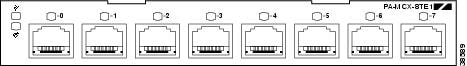
The PA-MCX port adapters (see Figure 1-1, Figure 1-2, and Figure 1-3) are multichannel port adapters that provide T1/E1 connectivity for data and voice traffic. The PA-MCX ports can be configured either as DS1/PRI ports for data traffic, or as packet voice ports that, when used in conjunction with a digital voice port adapter, allow Cisco 7200 VXR routers to become dedicated packet voice hubs or packet voice gateways that connect to both private branch exchanges (PBXs) and the Public Switched Telephone Network (PSTN). This allows packet voice and packet fax calls to be placed over the WAN and sent through the gateway into the traditional circuit-switched voice infrastructure.
Figure 1-1 PA-MCX-2TE1 Port Adapter
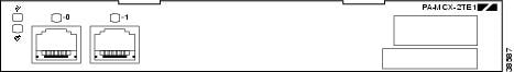
Figure 1-2 PA-MCX-4TE1 Port Adapter
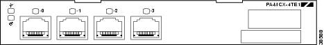
Figure 1-3 PA-MCX-8TE1 Port Adapter
Channelized T1/E1 Overview
When you are running channelized data, each DS1 interface can provide up to 24 T1 channel groups if your PA-MCX is configured for T1, or 31 E1 channel groups if your PA-MCX is configured for E1. The T1 groups are numbered from 0 to 23 and the E1 groups are numbered from 0 to 30. Each T1 channel group provides up to twenty-four 64-kbps time slots (DS0 channels), which are numbered 1 to 24. Each E1 channel group provides up to thirty-one 64-kbps time slots (E1 channels), which are numbered 1 to 31. Multiple time slots can be mapped to a single channel group. Each channel group is presented to the system as a serial interface that can be configured individually. Usable bandwidth for each channel group is calculated as n x 56 kbps or n x 64 kbps, where n is a number of DS0 time slots (1 to 24) or E1 channels (1 to 31).
When you are running ISDN PRI, each T1 interface provides 23 bearer (B) channels that can transmit and receive data at the rate of 64 kbps, full-duplex, and one data (D) channel that can transmit and receive data at the rate of 64 kbps, full-duplex. Each E1 interface provides 30 bearer (B) channels that can transmit and receive data at the rate of 64 kbps, full-duplex, and one data (D) channel that can transmit and receive data at the rate of 64 kbps, full-duplex. The B channels are used for transmitting user data. The D channel is used for call setup control and network connection teardown, and provides the communication from the router to the ISDN switch. The B and D channels are presented to the system as serial interfaces that support High-Level Data Link Control (HDLC) and Point-to-Point Protocol (PPP) encapsulation. The multichannel PA-MCX port adapter supports dial-on-demand routing (DDR) when you are running ISDN PRI.
Each of the channels on the PA-MCX uses a portion of the bandwidth (fractional T1 or E1) or the entire bandwidth for data transmission. Usable bandwidth for each channel is n x 64 kbps or n x 56 kbps, where n is a number from 1 to 24 for T1 and 1 to 31 for E1. When you are not running at full T1/E1 speeds, the unused portion of the bandwidth cannot be used and is filled with idle channel data.

Note ![]() Time slots on the PA-MCX port adapter are numbered 1 to 24 for T1 and 1 to 31 for E1, instead of the zero-based scheme (0 to 23 or 0 to 30) used with other Cisco products. This numbering scheme is to ensure consistency with telco numbering schemes for T1 and E1 channels within channelized equipment.
Time slots on the PA-MCX port adapter are numbered 1 to 24 for T1 and 1 to 31 for E1, instead of the zero-based scheme (0 to 23 or 0 to 30) used with other Cisco products. This numbering scheme is to ensure consistency with telco numbering schemes for T1 and E1 channels within channelized equipment.
The PA-MCX supports Facility Data Link (FDL) in Extended Superframe (ESF) framing on T1 networks, as well as network and payload loopbacks. Bit error rate testing (BERT) is supported on each of the T1 or E1 links. BERT can be run only on one port at a time.
Note ![]() On a PA-MCX configured for T1, BERT is done only over a framed T1 signal.
On a PA-MCX configured for T1, BERT is done only over a framed T1 signal.
The PA-MCX port adapter does not support the aggregation of multiple T1s or E1s (called inverse muxing or bonding) for higher bandwidth data rates. The multichannel PA-MCX port adapter supports Cisco HDLC, Frame Relay, PPP, and Switched Multimegabit Data Service (SMDS) Data Exchange Interface (DXI) encapsulations over each T1 or E1 link. For SMDS only, DXI is sent on the T1 or E1 line, so it needs to connect to an SMDS switch that has direct DXI input.
Multichannel Packet Voice Overview
The PA-MCX contains a TDM switch that provides a non-blocking switch capacity of 2048 x 2048 64-kbps pulse code modulation (PCM) channels at 8192 Mbps and two TDM rate adoption switches that multiplex and demultiplex the input and output streams of the TDM switch.
In Voice over IP (VoIP), the digital signal processor (DSP) segments the voice signal into frames, which are then coupled in groups of two and stored in voice packets. These voice packets are transported using IP in compliance with ITU-T specification H.323. Because Voice over IP is a delay-sensitive application, you must have a well-engineered network end-to-end to use it successfully. Fine-tuning your network to adequately support Voice over IP involves a series of protocols and features geared toward quality of service (QoS). Traffic shaping considerations must be taken into account to ensure the reliability of the voice connection.
Features
The PA-MCX has the following features:
•![]() Universal ports—Two, four, or eight interface ports per port adapter are configurable as either T1 (with integrated CSU/DSU) or E1 (with integrated G.703/G.704 120-ohm interface). Additionally, a port may be configured on a per-DS0 basis for voice termination, TDM pass-through (cross-connect), or packet data.
Universal ports—Two, four, or eight interface ports per port adapter are configurable as either T1 (with integrated CSU/DSU) or E1 (with integrated G.703/G.704 120-ohm interface). Additionally, a port may be configured on a per-DS0 basis for voice termination, TDM pass-through (cross-connect), or packet data.
•![]() Multiservice Interchange (MIX) support—Voice channels can be TDM-switched between port adapter slots in the Cisco 7200 VXR chassis. This allows DSP resources to be shared between port adapters in the same chassis or for port-to-port DS0 cross-connect between port adapter slots.
Multiservice Interchange (MIX) support—Voice channels can be TDM-switched between port adapter slots in the Cisco 7200 VXR chassis. This allows DSP resources to be shared between port adapters in the same chassis or for port-to-port DS0 cross-connect between port adapter slots.
•![]() DS0 drop and insert—Flexible TDM cross-connect capability between ports in the same port adapter is available.
DS0 drop and insert—Flexible TDM cross-connect capability between ports in the same port adapter is available.
•![]() VoIP and VoFR termination—Full VoIP and Voice over Frame Relay (V0FR) gateway functionality for mixed environments is available.
VoIP and VoFR termination—Full VoIP and Voice over Frame Relay (V0FR) gateway functionality for mixed environments is available.
•![]() Multiple clocking options—Ports can be clocked internally from the network, or the network clock from one port can be sent to the other port on the card or to other cards across the MIX bus in the Cisco 7200 VXR chassis. In data mode, each port can be configured as a separate clock source.
Multiple clocking options—Ports can be clocked internally from the network, or the network clock from one port can be sent to the other port on the card or to other cards across the MIX bus in the Cisco 7200 VXR chassis. In data mode, each port can be configured as a separate clock source.
•![]() Flexible signaling support—Channel-associated signaling (CAS) and common channel signaling (CCS) support is available for both E1 and T1 applications in H.323 environments.
Flexible signaling support—Channel-associated signaling (CAS) and common channel signaling (CCS) support is available for both E1 and T1 applications in H.323 environments.
Port Configured as T1 Features
•![]() DS1 100-ohm interfaces with RJ-48C connectors
DS1 100-ohm interfaces with RJ-48C connectors
•![]() D4 Super Frame (SF) and Extended Superframe (ESF) framing
D4 Super Frame (SF) and Extended Superframe (ESF) framing
•![]() Alternate mark inversion (AMI) or binary 8-zero substitution (B8ZS) line encoding
Alternate mark inversion (AMI) or binary 8-zero substitution (B8ZS) line encoding
•![]() Full Facility Data Link (FDL) support and FDL performance monitoring per ANSI T1.403 or AT&T TR 54016
Full Facility Data Link (FDL) support and FDL performance monitoring per ANSI T1.403 or AT&T TR 54016
•![]() Selectable DSX-1 cable length in increments from 0 to 655 feet (0 to 196.5 meters)
Selectable DSX-1 cable length in increments from 0 to 655 feet (0 to 196.5 meters)
•![]() Selectable DS1 CSU line build-out—0, -7.5, -15, and -22.5 dB
Selectable DS1 CSU line build-out—0, -7.5, -15, and -22.5 dB
•![]() Selectable DS1 CSU receiver gain—26 or 36 dB
Selectable DS1 CSU receiver gain—26 or 36 dB
•![]() DS1 line protection per UL1459/1950, FCC part 68
DS1 line protection per UL1459/1950, FCC part 68
•![]() Full support for DSX-1 Management Information Base (MIB), RFC 1406, including alarm detection and reporting
Full support for DSX-1 Management Information Base (MIB), RFC 1406, including alarm detection and reporting
•![]() DSX-1 MIB remote access supported
DSX-1 MIB remote access supported
Port Configured as E1 Features
•![]() E1 120-ohm (G.703) with RJ-48C connectors
E1 120-ohm (G.703) with RJ-48C connectors
•![]() Software-configurable E1 national bits
Software-configurable E1 national bits
•![]() Bipolar with 3-zero substitution (B3ZS) encoding
Bipolar with 3-zero substitution (B3ZS) encoding
•![]() Full support for E1 MIB, RFC 1406, including alarm detection and reporting
Full support for E1 MIB, RFC 1406, including alarm detection and reporting
Full BERT Capabilities on Each E1/T1
•![]() Programmable pseudorandom pattern up to 24 bits in length, including 211-1, 215-1, 220-1, 220-1 QRSS, 233-1, all zeros, all ones, and alternating ones and zeros
Programmable pseudorandom pattern up to 24 bits in length, including 211-1, 215-1, 220-1, 220-1 QRSS, 233-1, all zeros, all ones, and alternating ones and zeros
•![]() 32-bit-error count registers
32-bit-error count registers
Supported Loopbacks
•![]() Line loopback—T1/E1 stream is loopbacked at the line interface unit (LIU) toward the network.
Line loopback—T1/E1 stream is loopbacked at the line interface unit (LIU) toward the network.
•![]() Payload loopback—T1/E1 data stream is loopbacked at the framer toward the network.
Payload loopback—T1/E1 data stream is loopbacked at the framer toward the network.
•![]() Diagnostic local loopback—T1/E1 data stream is loopbacked at the framer toward the system.
Diagnostic local loopback—T1/E1 data stream is loopbacked at the framer toward the system.
•![]() Remote loopback—T1 stream is loopbacked at the LIU toward the network upon request from the far-end through the FDL command.
Remote loopback—T1 stream is loopbacked at the LIU toward the network upon request from the far-end through the FDL command.
DSP Features
The following DSP features are available only when used in conjunction with a PA-VXB or PA-VXC port adapter.
•![]() Full-featured DSP firmware—Support exists for eight standard-compression algorithms plus echo cancellation, full dual tone multi frequency (DTMF)/MF tone detection and generation, and dial-pulse generation.
Full-featured DSP firmware—Support exists for eight standard-compression algorithms plus echo cancellation, full dual tone multi frequency (DTMF)/MF tone detection and generation, and dial-pulse generation.
•![]() Silence suppression—To conserve network bandwidth, voice activity detection prevents sending data when no voice is present. Comfort-noise generation prevents uncomfortable dead silence on the receiving end.
Silence suppression—To conserve network bandwidth, voice activity detection prevents sending data when no voice is present. Comfort-noise generation prevents uncomfortable dead silence on the receiving end.
•![]() Coders-decoders (codecs)
Coders-decoders (codecs)
–![]() G.711 (a-law/mu-law), G.729/G.729.a (with "b" variant), G.723.1, G.728, G.726
G.711 (a-law/mu-law), G.729/G.729.a (with "b" variant), G.723.1, G.728, G.726
•![]() Fax relay through T.30 support
Fax relay through T.30 support
–![]() V.17, V.29, V.27
V.17, V.29, V.27
•![]() Echo cancellation—32 ms meeting G.165
Echo cancellation—32 ms meeting G.165
•![]() DTMF/R2/MF/SF/CP tone detection and generation
DTMF/R2/MF/SF/CP tone detection and generation
•![]() Dial-pulse detection and generation
Dial-pulse detection and generation
•![]() Energy-based voice activity detection (VAD) and codec-specific VAD
Energy-based voice activity detection (VAD) and codec-specific VAD
•![]() Comfort-noise generator
Comfort-noise generator
Signaling Supported for H.323 Environments
•![]() H.323 V.2 support
H.323 V.2 support
•![]() T1 CAS (robbed-bit signaling)
T1 CAS (robbed-bit signaling)
•![]() CCS signaling—E1 and T1 ISDN PRI (user and network side), Q.SIG
CCS signaling—E1 and T1 ISDN PRI (user and network side), Q.SIG
•![]() R2 signaling
R2 signaling
List of Terms
Call leg—A logical connection between the router and either a telephony endpoint over a bearer channel or another endpoint using a session protocol.
Channel-associated signaling (CAS)—A form of signaling used on a T1 line. With CAS, a signaling element is dedicated to each channel in the T1 frame. This type of signaling is sometimes called robbed-bit signaling (RBS) because a bit is taken out (or robbed) from the user's data stream to provide signaling information to and from the switch.
CIR—Committed Information Rate. The average rate of information transfer a subscriber (for example, the network administrator) has stipulated for a Frame Relay PVC.
Codec—Coder-decoder compression scheme or technique. In Voice over IP, it specifies the voice coder rate of speech for a dial peer.
Dial peer—An addressable call endpoint. In Voice over IP, there are two kinds of dial peers: POTS and VoIP.
DS0—A 64-kbps channel on an E1 or T1 WAN interface.
DTMF—Dual tone multi frequency. Use of two simultaneous voice-band tones for dial (such as touch tone).
E&M—Stands for recEive and transMit (or Ear and Mouth). E&M is a trunking arrangement generally used for two-way switch-to-switch or switch-to-network connections. Cisco's E&M interface is an RJ-48 connector that allows connections to PBX trunk lines (tie lines).
FIFO—First-in, first-out. In data communication, FIFO refers to a buffering scheme in which the first byte of data entering the buffer is the first byte retrieved by the CPU. In telephony, FIFO refers to a queuing scheme in which the first calls received are the first calls processed.
FRF.11—Frame Relay Forum implementation agreement for Voice over Frame Relay (Version 1.0, May 1997). This specification defines multiplexed data, voice, fax, DTMF digit-relay, and CAS/robbed-bit signaling frame formats but does not include call setup, routing, or administration facilities.
FRF.12—FRF implementation agreement (also known as FRF.11 Annex C) developed to allow long data frames to be fragmented into smaller pieces and interleaved with real-time frames. In this way, real-time voice and non-real-time data frames can be carried together on lower-speed links without causing excessive delay to the real-time traffic.
FXO—Foreign Exchange Office. Interface that connects to the PSTN central office and is the interface offered on a standard telephone. The Cisco FXO interface is an RJ-11 connector that allows an analog connection to be directed at the PSTN central office. This interface is of value for off-premises extension applications.
FXS—Foreign Exchange Station. Interface that connects directly to a standard telephone and supplies ring, voltage, and dial tone. The Cisco FXS interface is an RJ-11 connector that allows connections to basic telephone service equipment, key sets, and PBXs.
Multilink PPP—Multilink Point-to-Point Protocol. This protocol is a method of splitting, recombining, and sequencing datagrams across multiple logical data links.
PBX—Private branch exchange. Privately owned central switching office.
PLAR—Private Line Auto Ringdown. Type of service resulting in a call attempt to some particular remote endpoint when the local extension is taken off-key.
POTS—Plain Old Telephone Service. Basic telephone service supplying standard single-line telephones, telephone lines, and access to the Public Switched Telephone Network.
POTS dial peer—Dial peer connected through a traditional telephony network. POTS peers point to a particular voice port on a voice network device.
PSTN—Public Switched Telephone Network. PSTN refers to the local telephone company.
PVC—Permanent virtual circuit.
QoS—Quality of service, which refers to the measure of service quality provided to the user.
RSVP—Resource Reservation Protocol. This protocol supports the reservation of resources across an IP network.
VoIP dial peer—Dial peer connected through a packet network; in the case of Voice over IP, this is an IP network. VoIP peers point to specific VoIP devices.
Voice Primer
To understand Cisco's voice implementations, it helps to have some understanding of analog and digital transmission and signaling. This section provides some very basic, abbreviated voice telephony information as background to help you configure Voice over IP and Voice over Frame Relay, and includes the following topics:
•![]() Echo
Echo
Numbering Scheme
The standard PSTN is basically a large, circuit-switched network. It uses a specific numbering scheme, which complies with the ITU-T E.164 recommendations. For example, in North America, the North American Numbering Plan (NANP) is used, which consists of an area code, an office code, and a station code. Area codes are assigned geographically, office codes are assigned to specific switches, and station codes identify a specific port on that switch. The format in North America is 1Nxx-Nxx-xxxx, where N is a digit between 2 and 9 and x is a digit between 0 and 9. Internationally, each country is assigned a one- to three-digit country code; the country's dialing plan follows the country code. In Cisco voice implementations, numbering schemes are configured using the destination-pattern command.
Analog Versus Digital
Until recently, the telephone network was based on an analog infrastructure. Analog transmission is not particularly robust or efficient at recovering from line noise. Because analog signals degrade over distance, they need to be periodically amplified; this amplification boosts both the voice signal and ambient line noise, resulting in degradation of the quality of the transmitted sound.
In response to the limitations of analog transmission, the telephony network migrated to digital transmission using pulse code modulation (PCM) or adaptive differential pulse code modulation (ADPCM). In both cases, analog sound is converted into digital form by sampling the analog sound 8000 times per second and converting each sample into a numeric code.
Codecs
PCM and ADPCM are examples of "waveform" coder-decoder (codec) techniques. Waveform codecs are compression techniques that exploit the redundant characteristics of the waveform itself. In addition to waveform codecs, there are source codecs that compress speech by sending only simplified parametric information about voice transmission; these codecs require less bandwidth. Source codecs include linear predictive coding (LPC), code-excited linear prediction (CELP), and multipulse, multilevel quantization (MP-MLQ).
Coding techniques are standardized by the ITU-T in its G-series recommendations. The most popular coding standards for telephony and voice packet are:
•![]() G.711—Describes the 64-kbps PCM voice-coding technique. In G.711, encoded voice is already in the correct format for digital voice delivery in the Public Switched Telephone Network (PSTN) or through PBXs.
G.711—Describes the 64-kbps PCM voice-coding technique. In G.711, encoded voice is already in the correct format for digital voice delivery in the Public Switched Telephone Network (PSTN) or through PBXs.
•![]() G.723.1—Describes a compression technique that can be used for compressing speech or audio signal components at a very low bit rate as part of the H.324 family of standards. This codec has two bit rates associated with it: 5.3 and 6.3 kbps. The higher bit rate is based on ML-MLQ technology and provides a somewhat higher quality of sound. The lower bit rate is based on CELP and provides system designers with additional flexibility.
G.723.1—Describes a compression technique that can be used for compressing speech or audio signal components at a very low bit rate as part of the H.324 family of standards. This codec has two bit rates associated with it: 5.3 and 6.3 kbps. The higher bit rate is based on ML-MLQ technology and provides a somewhat higher quality of sound. The lower bit rate is based on CELP and provides system designers with additional flexibility.
•![]() G.726—Describes ADPCM coding at 40, 32, 24, and 16 kbps. ADPCM-encoded voice can be interchanged between packet voice, PSTN, and PBX networks if the PBX networks are configured to support ADPCM.
G.726—Describes ADPCM coding at 40, 32, 24, and 16 kbps. ADPCM-encoded voice can be interchanged between packet voice, PSTN, and PBX networks if the PBX networks are configured to support ADPCM.
•![]() G.728—Describes a 16-kbps low-delay variation of CELP voice compression. CELP voice coding must be translated into a public telephony format for delivery to or through the PSTN.
G.728—Describes a 16-kbps low-delay variation of CELP voice compression. CELP voice coding must be translated into a public telephony format for delivery to or through the PSTN.
•![]() G.729—Describes CELP compression where voice is coded into 8-kbps streams. There are two variations of this standard (G.729 and G.729 Annex A) that differ mainly in computational complexity; both provide speech quality similar to 32-kbps ADPCM.
G.729—Describes CELP compression where voice is coded into 8-kbps streams. There are two variations of this standard (G.729 and G.729 Annex A) that differ mainly in computational complexity; both provide speech quality similar to 32-kbps ADPCM.
In Cisco voice implementations, compression schemes are configured using the codec command.
Mean Opinion Score
Each codec provides a certain quality of speech. The quality of transmitted speech is a subjective response of the listener. A common benchmark used to determine the quality of sound produced by specific codecs is the mean opinion score (MOS). With the MOS, a wide range of listeners judge the quality of a voice sample (corresponding to a particular codec) on a scale of 1 (bad) to 5 (excellent). The scores are averaged to provide the mean opinion score for that sample. Table 1-1 shows the relationship between codecs and the MOS.
Although it might seem logical from a financial standpoint to convert all calls to low-bit rate codecs to save on infrastructure costs, you should exercise additional care when designing voice networks with low-bit-rate compression. There are drawbacks to compressing voice. One of the main drawbacks is signal distortion due to multiple encoding (called tandem encoding). For example, when a G.729 voice signal is tandem encoded three times, the MOS from 3.92 (very good) to 2.68 (unacceptable). Another drawback is codec-induced delay with low-bit-rate codecs.
Delay
One of the most important design considerations in implementing voice is minimizing one-way, end-to-end delay. Voice traffic is real-time traffic; if there is too long a delay in voice packet delivery, speech is unrecognizable. Delay is inherent in voice networking and is caused by a number of different factors. An acceptable delay is less than 200 milliseconds.
There are basically two kinds of delay inherent in today's telephony networks: propagation delay and handling delay. Propagation delay is caused by the characteristics of the speed of light traveling through a fiber-optic-based or copper-based media. Handling delay (sometimes called serialization delay) is caused by the devices that handle voice information. Handling delays have a significant impact on voice quality in a packetized network.
Codec-induced delays are considered a handling delay. Table 1-2 shows the delay introduced by different codecs.
Another handling delay is the time it takes to generate a voice packet. In Voice over IP, the DSP generates a frame every 10 milliseconds. Two of these frames are then placed within one voice packet; the packet delay is therefore 20 milliseconds.
Another source of handling delay is the time it takes to move the packet to the output queue. Cisco IOS software expedites the process of determining packet destination and getting the packet to the output queue. The actual delay at the output queue is another source of handling delay and should be kept to under 10 milliseconds whenever possible by using whatever queuing methods are optimal for your network. Output queue delays are a quality of service (QoS) issue in Voice over IP for Cisco 7200 VXR routers, and are discussed in the "Configuring IP Networks for Real-Time Voice Traffic" section on page 4-15.
In Voice over Frame Relay, you need to make sure that voice traffic is not crowded out by data traffic. Strategies on how to manage Voice over Frame Relay voice traffic are discussed in the "Configuring Voice over Frame Relay" section on page 4-37.
Jitter
Jitter is another factor that affects delay. Jitter occurs when there is a variation between when a voice packet is expected to be received and when it actually is received, causing a discontinuity in the real-time voice stream. Voice devices such as the Cisco 7200 VXR routers with PA-MCX port adapters compensate for jitter by setting up a playout buffer to play back voice in a smooth fashion. Playout control is handled through Real-Time Transfer Protocol (RTP) encapsulation, either by selecting adaptive or nonadaptive playout-delay mode. In either mode, the default value for nominal delay is sufficient.
End-to-End Delay
Figuring out the end-to-end delay is not difficult if you know the end-to-end signal paths or data paths, the codec, and the payload size of the packets. Adding the delays from the endpoints to the codecs at both ends, the encoder delay (which is 5 milliseconds for G.711 and G.726 codecs and 10 milliseconds for the G.729 codec), the packetization delay, and the fixed portion of the network delay yield the end-to-end delay for the connection.
Echo
Echo is hearing your own voice in the telephone receiver while you are talking. When timed properly, echo is reassuring to the speaker; if the echo exceeds approximately 25 milliseconds, it can be distracting and cause breaks in the conversation. In a traditional telephony network, echo is normally caused by a mismatch in impedance from the four-wire network switch conversion to the two-wire local loop and is controlled by echo cancelers. In voice packet-based networks, echo cancelers are built into the low-bit-rate codecs and are operated on each digital signal processor (DSP). Echo cancelers are limited by design by the total amount of time they wait for the reflected speech to be received, which is known as an echo trail. The echo trail is normally 32 milliseconds.
In Cisco voice implementations, echo cancelers are enabled using the echo-cancel enable command. The echo trails are configured using the echo-cancel-coverage command. For example, Voice over IP has configurable echo trails of 16, 24, and 32 milliseconds.
Signaling
Although there are various types of signaling used in telecommunications today, this document describes only those with direct applicability to Cisco voice implementations. The first one involves access signaling, which determines when a line has gone off-hook or on-hook (in other words, dial tone). Foreign Exchange Office (FXO) and Foreign Exchange Station (FXS) are types of access signaling. There are two common methods of providing this basic signal:
•![]() Loop start is the most common technique for access signaling in a standard PSTN end-loop network. When a handset is picked up (goes off-hook), this action closes the circuit that draws current from the telephone company central office (CO), indicating a change in status. This change in status signals the CO to provide dial tone. An incoming call is signaled from the CO to the handset by sending a signal in a standard on/off pattern, which causes the telephone to ring.
Loop start is the most common technique for access signaling in a standard PSTN end-loop network. When a handset is picked up (goes off-hook), this action closes the circuit that draws current from the telephone company central office (CO), indicating a change in status. This change in status signals the CO to provide dial tone. An incoming call is signaled from the CO to the handset by sending a signal in a standard on/off pattern, which causes the telephone to ring.
•![]() Ground start is another access signaling method used to indicate on-hook or off-hook status to the CO, but this signaling method is primarily used on trunk lines or tie lines between PBXs. Ground start signaling works by using ground and current detectors. This allows the network to indicate off-hook or seizure of an incoming call independently of the ringing signal.
Ground start is another access signaling method used to indicate on-hook or off-hook status to the CO, but this signaling method is primarily used on trunk lines or tie lines between PBXs. Ground start signaling works by using ground and current detectors. This allows the network to indicate off-hook or seizure of an incoming call independently of the ringing signal.
In Cisco voice implementations, access signaling is configured using the signal command.
Another signaling technique used mainly between PBXs or other network-to-network telephony switches is known as E&M. There are five types of E&M signaling, as well as two different wiring methods. The Cisco voice implementation supports E&M types I, II, III, and V, using both two-wire and four-wire implementations. In Cisco voice implementations, E&M signal types are configured using the type command.
LEDs
As shown in Figure 1-4, Figure 1-5, and Figure 1-6, the PA-MCX port adapters have a green enabled LED, a bicolor alarm LED, and one bicolor port status LED, one for each port on the port adapter. Table 1-3 lists the colors and functions of the LEDs.
Figure 1-4 PA-MCX-2TE1 Port Adapter Front Panel LEDs
Figure 1-5 PA-MCX-4TE1 Port Adapter Front Panel LEDs
Figure 1-6 PA-MCX-8TE1 Port Adapter Front Panel LEDs
Cables, Connectors, and Pinouts
The T1/E1 interface receptacles on the PA-MCX port adapters are RJ-48C for both T1 (100-ohm) and E1 (120-ohm).
After you properly connect a port to a line, it takes approximately 30 seconds for Cisco IOS to report that the line is up.
Each connection supports T1 (100-ohm) or E1 (120-ohm) interfaces that meet T1.403 and ACCUNET TR62411 standards. The RJ-48C connection does not require an external transceiver. The DS1 ports are T1 interfaces that use foil twisted-pair cables.
Shielded cables (FTP [foil twisted-pair]) with 120-ohm impedance are required to comply with CE marking requirements.
Figure 1-7 shows the PA-MCX port adapter interface cable connector. See the "Connecting Interface Cables" section on page 3-5 for directions on connecting the cables to a PA-MCX port adapter.
Figure 1-7 PA-MCX Port Adapter Interface Connector
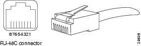
Table 1-4 lists the signal pinouts and descriptions for the RJ-48C connector.
|
|
|
|---|---|
1 |
RX tip |
2 |
RX ring |
3 |
No connection |
4 |
TX tip |
5 |
TX ring |
6 |
No connection |
7 |
No connection |
8 |
No connection |

Warning ![]() To reduce the risk of fire, use only 26 AWG or larger telecommunication line cord. Statement 1023
To reduce the risk of fire, use only 26 AWG or larger telecommunication line cord. Statement 1023
Port Adapter Slot Locations on the Supported Platform
This section discusses port adapter slot locations on the supported platform. The illustration that follows summarizes the slot location conventions.
Note ![]() Interface ports are numbered from left to right starting with 0.
Interface ports are numbered from left to right starting with 0.
Cisco 7200 VXR Routers Slot Numbering
Figure 1-8 shows a Cisco 7206VXR with port adapters installed. In the Cisco 7206VXR, port adapter slot 1 is in the lower left position, and port adapter slot 6 is in the upper right position. (The Cisco 7204VXR is not shown; however, the PA-MCX port adapters can be installed in any available port adapter slot. Slot 0 is always reserved for the Fast Ethernet port on the I/O controller—if present.)
Figure 1-8 Port Adapter Slots in the Cisco 7206 VXR

Identifying Interface Addresses
This section describes how to identify interface addresses for the PA-MCX port adapters in the supported platform. Interface addresses specify the actual physical location of each interface on a router or switch.
Interfaces on the PA-MCX port adapters installed in a router maintain the same address regardless of whether other port adapters are installed or removed. However, when you move a port adapter to a different slot, the first number in the interface address changes to reflect the new port adapter slot number.
Table 1-5 explains how to identify interface addresses.
|
|
|
|
|
|---|---|---|---|
Cisco 7200 VXR routers |
Port-adapter-slot-number/interface-port-number |
Port adapter slot—0 through 6 (depends on the number of slots in the router)1 Interface port—0 through 7 (depends on the number of ports in the port adapter) |
1/0 |
1 Port adapter slot 0 is reserved for the Fast Ethernet port on the I/O controller (if present). |
Cisco 7200 VXR Router Interface Addresses
This section describes how to identify the interface addresses used for the PA-MCX port adapters in Cisco 7200 VXR routers. The interface address is composed of a two-part number in the format port-adapter-slot-number/interface-port-number. See Table 1-5 for the interface address format.
In Cisco 7200 VXR routers, port adapter slots are numbered from the lower left to the upper right, beginning with port adapter slot 1 and continuing through port adapter slot 4 for the Cisco 7204VXR, and slot 6 for the Cisco 7206VXR. (Port adapter slot 0 is reserved for the optional Fast Ethernet port on the I/O controller—if present.)
The interface addresses of the interfaces on an eight-port PA-MCX port adapter in port adapter slot 1 are 1/0 through 1/7 (port adapter slot 1 and interfaces 0 through 7). If the PA-MCX was in port adapter slot 4, these same interfaces would be numbered 4/0 through 4/7 (port adapter slot 4 and interfaces 0 through 7).
 Feedback