- Title and copyright: PA-4T+ Synchronous Serial Port Adapter Installation and Configuration
- Preface: PA-4T+ Synchronous Serial Port Adapter Installation and Configuration
- Overview: PA-4T+ Synchronous Serial Port Adapter Installation and Configuration
- Preparing to Install the PA-4T+ Synchronous Serial Port Adapter
- Removing and Installing the PA-4T+ Synchronous Serial Port Adapter
- Attaching the PA-4T+ Interface Cables
- Configuring the PA-4T+ Synchronous Serial Port Adapter
PA-4T+ Synchronous Serial Port Adapter Installation and Configuration
Bias-Free Language
The documentation set for this product strives to use bias-free language. For the purposes of this documentation set, bias-free is defined as language that does not imply discrimination based on age, disability, gender, racial identity, ethnic identity, sexual orientation, socioeconomic status, and intersectionality. Exceptions may be present in the documentation due to language that is hardcoded in the user interfaces of the product software, language used based on RFP documentation, or language that is used by a referenced third-party product. Learn more about how Cisco is using Inclusive Language.
- Updated:
- September 14, 2007
Chapter: Overview: PA-4T+ Synchronous Serial Port Adapter Installation and Configuration
- Port Adapter Overview
- Synchronous Serial Overview
- Serial Interface Specifications
- LEDs
- Cables, Connectors, and Pinouts
- Port Adapter Slot Locations on the Supported Platforms
- Catalyst RSM/VIP2 Slot Numbering
- Catalyst 6000 Family FlexWAN Module Slot Numbering
- Cisco 7100 Series Routers Slot Numbering
- Cisco 7200 Series Routers and Cisco 7200 VXR Routers Slot Numbering
- Cisco uBR7200 Series Router Slot Numbering
- Cisco 7201 Router Slot Numbering
- Cisco 7301 Router Slot Numbering
- Cisco 7304 PCI Port Adapter Carrier Card Slot Numbering
- Cisco 7401ASR Router Slot Numbering
- Cisco 7000 Series Routers and Cisco7500 Series Routers VIP Slot Numbering
- Identifying Interface Addresses
- Catalyst RSM/VIP2 Interface Addresses
- Catalyst 6000 Family FlexWAN Module
- Cisco 7100 Series Routers Interface Addresses
- Cisco 7200 Series Routers and Cisco 7200 VXR Routers Interface Addresses
- Cisco uBR7200 Series Routers Interface Addresses
- Cisco 7201 Router Interface Addresses
- Cisco 7301 Router Interface Addresses
- Cisco 7304 PCI Port Adapter Carrier Card Interface Addresses
- Cisco 7401ASR Router Interface Addresses
- Cisco 7000 Series Routers and Cisco 7500 Series Routers VIP Interface Addresses
Overview
This chapter describes the PA-4T+ port adapter and contains the following sections:
•![]() Serial Interface Specifications
Serial Interface Specifications
•![]() LEDs
LEDs
•![]() Cables, Connectors, and Pinouts
Cables, Connectors, and Pinouts
•![]() Port Adapter Slot Locations on the Supported Platforms
Port Adapter Slot Locations on the Supported Platforms
•![]() Identifying Interface Addresses
Identifying Interface Addresses
Port Adapter Overview
The PA-4T+ provides the following electrical interfaces:
•![]() EIA/TIA-232
EIA/TIA-232
•![]() EIA/TIA-449
EIA/TIA-449
•![]() EIA-530. X.21
EIA-530. X.21
•![]() V.35
V.35
Each interface complies with its specific interface specifications. The cable attached to each PA-4T+ port adapter's interface ports determines its type (EIA/TIA-232 and so forth) and its mode (data communications equipment [DCE] or data terminal equipment [DTE]).

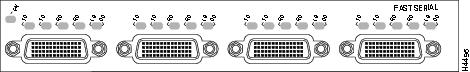
Note ![]() The PA-4T+, shown in Figure 1-1, provides enhanced performance over the PA-4T, shown in Figure 1-2. To determine if a PA-4T+ or PA-4T is installed in your router, view the port adapters' faceplate labels or use the show diag command to view installed interface types.
The PA-4T+, shown in Figure 1-1, provides enhanced performance over the PA-4T, shown in Figure 1-2. To determine if a PA-4T+ or PA-4T is installed in your router, view the port adapters' faceplate labels or use the show diag command to view installed interface types.
Figure 1-1 PA-4T+ —Faceplate View
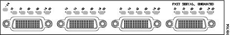
Figure 1-2 PA-4T Port Adapter—Faceplate View
The PA-4T+ provides four synchronous serial ports, and each port supports full-duplex operations at T1 and E1 speeds.
Speed is controlled by three variables:
•![]() The number of ports in use
The number of ports in use
•![]() The maximum speed allowed by the port adapter
The maximum speed allowed by the port adapter
•![]() The maximum speed of the attached CSU/DSU.
The maximum speed of the attached CSU/DSU.
The CSU/DSU determines the maximum speed of the full-duplex port. No configuration is necessary. If a CSU/DSU runs at a maximum speed of 1.55 Mbps (T1 speed), using only one port in the port adapter will not make this CSU/DSU run at E2 speed. On the other hand, if a CSU/DSU is capable of E2 speed (8 Mbps), this CSU/DSU will take the maximum bandwidth of the port adapter. To ensure this speed, no other port can be used. If you use another port, the speed of the CSU/DSU capable of E2 speed is reduced, because the port adapter shares the bandwidth between the two ports.
Note ![]() For running at speeds above 2 Mbps, the PA-H with appropriate DSU is a better choice.
For running at speeds above 2 Mbps, the PA-H with appropriate DSU is a better choice.
When two full-duplex ports are in use, the maximum speed for each is 4 Mbps. When four full-duplex ports are in use, the maximum speed for each is 1.55 Mbps (T1) or 2.048 Mbps (E1).
Synchronous Serial Overview
The PA-4T+ provides four channel-independent, synchronous serial ports that support full-duplex operation at T1 (1.544-Mbps) and E1 (2.048-Mbps) speeds. Each port supports any of the available interface types:
•![]() EIA/TIA-232
EIA/TIA-232
•![]() EIA/TIA-449
EIA/TIA-449
•![]() V.35, X.21
V.35, X.21
•![]() EIA-530
EIA-530
EIA/TIA-232, which is the most common interface standard in the U.S., supports unbalanced circuits at signal speeds up to 64 kbps. EIA/TIA-449, which supports balanced (EIA/TIA-422) and unbalanced (EIA/TIA-423) transmissions, is a faster (up to 2 Mbps) version of EIA/TIA-232 that provides more functions and supports transmissions over greater distances. The EIA/TIA-449 standard was intended to replace EIA/TIA-232, but it was not widely adopted.
Note ![]() The EIA/TIA standards were referred to as recommended standards called RS-232 and RS-449 prior to their acceptance by the ANSI committee.
The EIA/TIA standards were referred to as recommended standards called RS-232 and RS-449 prior to their acceptance by the ANSI committee.
The resistance to convert to EIA/TIA-449 was due primarily to the large installed base of DB-25 hardware and to the larger size of the 37-pin EIA/TIA-449 connectors, which limited the number of connections possible (fewer than is possible with the smaller, 25-pin EIA/TIA-232 connector).
EIA-530, which supports balanced transmission, provides the increased functionality, speed, and distance of EIA/TIA-449 on the smaller, DB-25 connector used for EIA/TIA-232. The EIA-530 standard was created to support the more sophisticated circuitry of EIA/TIA-449 on the large number of existing EIA/TIA-232 (DB-25) hardware instead of the larger, 37-pin connectors used for EIA/TIA-449. EIA-530 refers to the electrical specifications of EIA/TIA-422 and EIA/TIA-423. The specification recommends a maximum speed of 2 Mbps. EIA-530 is used primarily in the United States.
The V.35 interface is most commonly used in the United States and throughout Europe, and is recommended for speeds up to 48 kbps. The X.21 interface uses a 15-pin connection for balanced circuits and is commonly used in the United Kingdom to connect public data networks. X.21 relocates some of the logic functions to the data terminal equipment (DTE) and data communications equipment (DCE) interfaces and, as a result, requires fewer circuits and a smaller connector than EIA/TIA-232.
All interface types except EIA-530 can be individually configured for operation with either external (DTE mode) or internal (DCE mode) timing signals; EIA-530 operates with external timing only. In addition, all VIP serial interface types support nonreturn to zero (NRZ) and nonreturn to zero inverted (NRZI) format, and both 16-bit and 32-bit cyclic redundancy checks (CRCs). The default configuration is for NRZ format and 16-bit CRC. You can change the default settings with software commands. (For more information, see "Configuring the PA-4T+ Interfaces.")
There is no default mode or clock rate set on the VIP serial ports, although an internal clock signal is present on all ports for DCE support. The internal clock also allows you to perform local loopback tests without having to terminate the port or connect a cable. (All interface types except X.21 DTE support loopback.) To use the port as a DCE interface, you must set the clock rate and connect a DCE adapter cable. To use the port as a DTE interface, you need only connect a DTE adapter cable to the port. Because the serial adapter cables determine the mode and interface type, the PA-4T+ interface becomes a DTE when a DTE cable is connected to it.
If a DTE cable is connected to a port with a clock rate set, the DTE ignores the clock rate and uses the external clock signal that is sent from the remote DCE. For a brief description of the clockrate command, see "Configuring the PA-4T+ Interfaces." For complete command descriptions and instructions, see the publications listed in the section "Related Documentation" section.
Serial Interface Specifications
The PA-4T+ provides up to four synchronous serial interfaces. Each interface allows a maximum bandwidth of 2.048 Mbps; the speed depends on the type of electrical interface used. Use EIA/TIA-232 for speeds of 64 kilobits per second (kbps) and below, and use X.21, EIA/TIA-449, V.35, or EIA-530 for higher speeds.
Serial signals can travel a limited distance at any given bit rate; generally, the slower the baud rate, the greater the distance. All serial signals are subject to distance limits beyond which a signal degrades significantly or is completely lost.
Table 1-1 lists the recommended (standard) maximum speeds and distances for each PA-4T+ serial interface type. The recommended maximum rate for V.35 is 2.048 Mbps.
Balanced drivers allow EIA/TIA-449 signals to travel greater distances than EIA/TIA-232. The recommended distance limits for EIA/TIA-449 shown in Table 1-1 are also valid for V.35, X.21, and EIA-530. EIA/TIA-449 and EIA-530 support 2.048-Mbps rates, and V.35 supports 2.048-Mbps rates without any problems; we do not recommend exceeding published specifications for transmission speed versus distance. Do so at your own risk.
LEDs
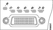
The PA-4T+ contains the ENABLED LED, standard on all port adapters, and one status LED for each port. After system initialization, the ENABLED LED goes on to indicate that the PA-4T+ has been enabled for operation. (The LEDs are shown in Figure 1-3.)
Figure 1-3 PA-4T+ LEDs
The following conditions must be met before the PA-4T+ is enabled:
•![]() The port adapter is correctly connected to the backplane midplane and receiving power.
The port adapter is correctly connected to the backplane midplane and receiving power.
•![]() A valid system software image for the port adapter has been downloaded successfully.
A valid system software image for the port adapter has been downloaded successfully.
•![]() The system software recognizes the port adapter or VIP with an installed PA-4T+.
The system software recognizes the port adapter or VIP with an installed PA-4T+.
If any of the above conditions are not met, or if the initialization fails for other reasons, the ENABLED LED will not go on.
Table 1-2 lists port LED status indications.
Cables, Connectors, and Pinouts
The following sections describe the serial receptacles on the PA-4T+ and the cables and pinouts for the various serial interface cables.
PA-4T+ Receptacles and Cables
The PA-4T+ and adapter cables allow a high density of interface ports, regardless of the size of the connectors typically used with each electrical interface type. All ports use an identical 60-pin D-shell receptacle that supports all interface types. Each port requires a serial adapter cable, which provides the interface between the high-density serial port and the standard connectors that are commonly used for each electrical interface type.
Note ![]() The adapter cable determines the electrical interface type and mode of the port (DTE or DCE) to which it is connected.
The adapter cable determines the electrical interface type and mode of the port (DTE or DCE) to which it is connected.
The network end of the cable is an industry-standard connector for the type of electrical interface that the cable supports. For most interface types, the adapter cable for DTE mode uses a plug at the network end, and the cable for DCE mode uses a receptacle at the network end. Exceptions are V.35 adapter cables, which are available with either a V.35 plug or a receptacle for either mode, and the EIA-530 adapter cable, which is available only in DTE mode with a DB-25 plug at the network end. The mode is labeled on the molded plastic connector shell at the ends of all cables except V.35 (which uses the standard Winchester block-type connector instead of a molded plastic D shell).
Following are the available interface cable options (and product numbers) for the mode and network-end connectors for each cable:
•![]() EIA/TIA-232: DTE mode with a DB-25 plug (CAB-232MT); DCE mode with a DB-25 receptacle (CAB-232FC).
EIA/TIA-232: DTE mode with a DB-25 plug (CAB-232MT); DCE mode with a DB-25 receptacle (CAB-232FC).
•![]() EIA/TIA-449: DTE mode with a 37-pin D-shell plug (CAB-449MT); DCE mode with a 37-pin D-shell receptacle (CAB-449C).
EIA/TIA-449: DTE mode with a 37-pin D-shell plug (CAB-449MT); DCE mode with a 37-pin D-shell receptacle (CAB-449C).
•![]() V.35: DTE mode or DCE mode with a 34-pin Winchester-type V.35 plug (CAB-V35MT or CAB-V35MC); DTE mode or DCE mode with a 34-pin Winchester-type V.35 receptacle (CAB-V35FT or CAB-V35FC). Also available is a cable with a male DB-60 plug on the router end and a male DB-34 shielded plug on the network end (CAB-V35MTS).
V.35: DTE mode or DCE mode with a 34-pin Winchester-type V.35 plug (CAB-V35MT or CAB-V35MC); DTE mode or DCE mode with a 34-pin Winchester-type V.35 receptacle (CAB-V35FT or CAB-V35FC). Also available is a cable with a male DB-60 plug on the router end and a male DB-34 shielded plug on the network end (CAB-V35MTS).
•![]() X.21: DTE mode with a DB-15 plug (CAB-X21MT); DCE mode with a DB-25 receptacle (CAB-X21FC).
X.21: DTE mode with a DB-15 plug (CAB-X21MT); DCE mode with a DB-25 receptacle (CAB-X21FC).
•![]() EIA-530: DTE mode with a DB-25 plug (CAB-530MT).
EIA-530: DTE mode with a DB-25 plug (CAB-530MT).
Note ![]() For cable pinouts, see the "PA-4T+ Port Adapter Cable Pinouts" section.
For cable pinouts, see the "PA-4T+ Port Adapter Cable Pinouts" section.
Figure 1-4 shows the serial port adapter cables for connection from the PA-4T+ port adapters to your network.
Figure 1-4 Serial Port Adapter Cables
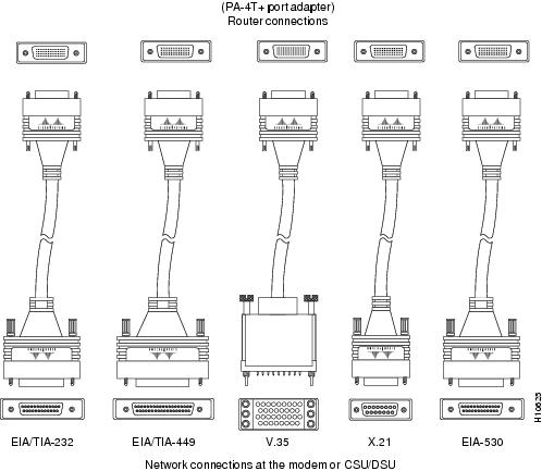
Metric (M3) thumbscrews are included with each port adapter cable to allow connections to devices that use metric hardware. Because the PA-4T+ uses a special, high-density port that requires special adapter cables for each electrical interface type, we recommend that you obtain serial interface cables from the factory.
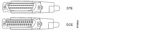
EIA/TIA-232 Connections
The router end of all EIA/TIA-232 adapter cables is a high-density 60-pin plug. The network end of the adapter cable is a standard 25-pin D-shell connector (known as a DB-25) that is commonly used for EIA/TIA-232 connections. Figure 1-5 shows the connectors at the network end of the adapter cable.
Note ![]() The system console and auxiliary ports on the Route Switch Processor (RSP) in the Cisco 7500 series also use EIA/TIA-232 connections; however, the PA-4T+ interfaces support synchronous serial connections, and the console and auxiliary ports only support asynchronous connections. Use caution when connecting EIA/TIA-232 cables to the PA-4T+ receptacles.
The system console and auxiliary ports on the Route Switch Processor (RSP) in the Cisco 7500 series also use EIA/TIA-232 connections; however, the PA-4T+ interfaces support synchronous serial connections, and the console and auxiliary ports only support asynchronous connections. Use caution when connecting EIA/TIA-232 cables to the PA-4T+ receptacles.
Note ![]() Do not use the Cisco Systems-provided EIA/TIA-232 adapter cable CAB-232MT= to connect a PA-4T+ interface that is configured for DTE mode directly to an NEC - NEXTSTAR 1E model C4969 MD/SAC unit interface that is configured for DCE mode. This action will keep transmit and receive data signals from being properly exchanged between the two interfaces.
Do not use the Cisco Systems-provided EIA/TIA-232 adapter cable CAB-232MT= to connect a PA-4T+ interface that is configured for DTE mode directly to an NEC - NEXTSTAR 1E model C4969 MD/SAC unit interface that is configured for DCE mode. This action will keep transmit and receive data signals from being properly exchanged between the two interfaces.
Instead, you must connect an additional, intermediate adapter cable—with standard EIA/TIA-232 DB-25 connectors at both ends—from the network end of CAB-232MT to the standard EIA/TIA-232 DB-25 connector (the DCE interface) on the NEC - NEXTSTAR 1E model C4969 MD/SAC unit. Cisco Systems does not provide this additional cable; however, the cable's signals and pin assignments are listed in Table 1-4.
Note ![]() You can use the Cisco Systems-provided EIA/TIA-232 adapter cable CAB-232FC to connect a PA-4T+ interface that is configured for DCE mode directly to an NEC - NEXTSTAR 1E model C4969 MD/SAC unit interface that is configured for DTE mode.
You can use the Cisco Systems-provided EIA/TIA-232 adapter cable CAB-232FC to connect a PA-4T+ interface that is configured for DCE mode directly to an NEC - NEXTSTAR 1E model C4969 MD/SAC unit interface that is configured for DTE mode.
Figure 1-5 EIA/TIA-232 Adapter Cable Connectors
EIA/TIA-449 Connections
The router end of all EIA/TIA-449 adapter cables is a high-density, 60-pin plug. The network end of the adapter cable provides a standard 37-pin D-shell connector, which is commonly used for EIA/TIA-449 connections. Figure 1-6 shows the connectors at the network end of the adapter cable. EIA/TIA-449 cables are available as either DTE (DB-37 plug) or DCE (DB-37 receptacle).
Figure 1-6 EIA/TIA-449 Adapter Cable Connectors

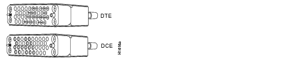
V.35 Connections
The router end of all V.35 adapter cables is a high-density, 60-pin plug. The network end of the adapter cable provides a standard 34-pin Winchester-type connector commonly used for V.35 connections. Figure 1-7 shows the connectors at the network end of the V.35 adapter cable. V.35 cables are available with a standard V.35 plug for DTE mode (CAB-V35MT) or a V.35 receptacle for DCE mode (CAB-V35FC).
Figure 1-7 V.35 Adapter Cable Connectors
Note ![]() Also available, but not shown in Figure 1-7, are CAB-V35MC, a V.35 cable with a plug on the network end for DCE mode, and CAB-V35FT, a V.35 cable with a receptacle on the network end for DTE mode. These cables are used for connecting V.35-equipped systems back to back.
Also available, but not shown in Figure 1-7, are CAB-V35MC, a V.35 cable with a plug on the network end for DCE mode, and CAB-V35FT, a V.35 cable with a receptacle on the network end for DTE mode. These cables are used for connecting V.35-equipped systems back to back.
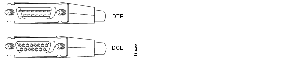
X.21 Connections
The router end of all X.21 adapter cables is a high-density, 60-pin plug. The network end of the adapter cable is a standard DB-15 connector. Figure 1-8 shows the connectors at the network end of the X.21 adapter cable. X.21 cables are available as either DTE (DB-15 plug) or DCE (DB-15 receptacle).
Figure 1-8 X.21 Adapter Cable Connectors
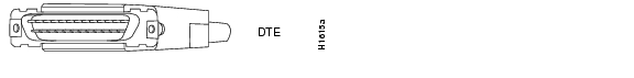
EIA-530 Connections
The EIA-530 adapter cable is available in DTE mode only. The router end of the EIA-530 adapter cable is a high-density, 60-pin plug. The network end of the adapter cable is a standard DB-25 plug commonly used for EIA/TIA-232 connections. Figure 1-9 shows the DB-25 connector at the network end of the adapter cable.
Figure 1-9 EIA-530 Adapter Cable Connector
PA-4T+ Port Adapter Cable Pinouts
All PA-4T+ ports use a a 60-pin receptacle that supports all available interface types. A special serial adapter cable determines the electrical interface type and mode of the interface. The router end of all of the adapter cables has a 60-pin plug; the connectors at the network end are the standard connectors used for the respective interfaces. All interface types except EIA-530 are available in DTE or DCE format: DTE with a plug at the network end and DCE with a receptacle at the network end. V.35 is available in either mode with either gender at the network end. EIA-530 is available in DTE only. The tables that follow list the signal pinouts for both the DTE and DCE mode serial port adapter cables for each of the following PA-4T+ interface types:
•![]() EIA/TIA-232 pinouts, Table 1-3
EIA/TIA-232 pinouts, Table 1-3
•![]() EIA/TIA-449 pinouts, Table 1-5
EIA/TIA-449 pinouts, Table 1-5
•![]() EIA-530 pinouts, Table 1-6
EIA-530 pinouts, Table 1-6
•![]() V.35 pinouts, Table 1-7
V.35 pinouts, Table 1-7
•![]() X.21 pinouts, Table 1-8
X.21 pinouts, Table 1-8
|
|
|
||||||||||
|---|---|---|---|---|---|---|---|---|---|---|---|
|
|
|
|
|
||||||||
|
|
|
|
|
|
|
|
|
||||
Shield ground |
46 |
1 |
Shield ground |
Shield ground |
46 |
1 |
Shield ground |
||||
TxD/RxD |
41 |
—> |
2 |
TxD |
RxD/TxD |
36 |
<— |
2 |
TxD |
||
RxD/TxD |
36 |
<— |
3 |
RxD |
TxD/RxD |
41 |
—> |
3 |
RxD |
||
RTS/CTS |
42 |
—> |
4 |
RTS |
CTS/RTS |
35 |
<— |
4 |
RTS |
||
CTS/RTS |
35 |
<— |
5 |
CTS |
RTS/CTS |
42 |
—> |
5 |
CTS |
||
DSR/DTR |
34 |
<— |
6 |
DSR |
DTR/DSR |
43 |
—> |
6 |
DSR |
||
Circuit ground |
45 |
7 |
Circuit ground |
Circuit ground |
45 |
7 |
Circuit ground |
||||
DCD/LL |
33 |
<— |
8 |
DCD |
LL/DCD |
44 |
—> |
8 |
DCD |
||
TxC/NIL |
37 |
<— |
15 |
TxC |
TxCE/TxC |
39 |
—> |
15 |
TxC |
||
RxC/TxCE |
38 |
<— |
17 |
RxC |
NIL/RxC |
40 |
—> |
17 |
RxC |
||
LL/DCD |
44 |
—> |
18 |
LTST |
DCD/LL |
33 |
<— |
18 |
LTST |
||
DTR/DSR |
43 |
—> |
20 |
DTR |
DSR/DTR |
34 |
<— |
20 |
DTR |
||
TxCE/TxC |
39 |
—> |
24 |
TxCE |
RxC/TxCE |
38 |
<— |
24 |
TxCE |
||
Mode 0 |
50 |
|
Mode 0 |
50 |
|
||||||
1 HD = high density. |
|
|
|
||||||||||
|---|---|---|---|---|---|---|---|---|---|---|---|
|
|
|
|
|
||||||||
|
|
|
|
|
|
|
|
|
||||
Shield ground |
46 |
1 |
Shield ground |
Shield ground |
46 |
1 |
Shield ground |
||||
TxD/RxD+ |
11 |
—> |
4 |
SD+ |
RxD/TxD+ |
28 |
<— |
4 |
SD+ |
||
TxD/RxD- |
12 |
—> |
22 |
SD- |
RxD/TxD- |
27 |
<— |
22 |
SD- |
||
TxC/RxC+ |
24 |
<— |
5 |
ST+ |
TxCE/TxC+ |
13 |
—> |
5 |
ST+ |
||
TxC/RxC- |
23 |
<— |
23 |
ST- |
TxCE/TxC- |
14 |
—> |
23 |
ST- |
||
RxD/TxD+ |
28 |
<— |
6 |
RD+ |
TxD/RxD+ |
11 |
—> |
6 |
RD+ |
||
RxD/TxD- |
27 |
<— |
24 |
RD- |
TxD/RxD- |
12 |
—> |
24 |
RD- |
||
RTS/CTS+ |
9 |
—> |
7 |
RS+ |
CTS/RTS+ |
1 |
<— |
7 |
RS+ |
||
RTS/CTS- |
10 |
—> |
25 |
RS- |
CTS/RTS- |
2 |
<— |
25 |
RS- |
||
RxC/TxCE+ |
26 |
<— |
8 |
RT+ |
TxC/RxC+ |
24 |
—> |
8 |
RT+ |
||
RxC/TxCE- |
25 |
<— |
26 |
RT- |
TxC/RxC- |
23 |
—> |
26 |
RT- |
||
CTS/RTS+ |
1 |
<— |
9 |
CS+ |
RTS/CTS+ |
9 |
—> |
9 |
CS+ |
||
CTS/RTS- |
2 |
<— |
27 |
CS- |
RTS/CTS- |
10 |
—> |
27 |
CS- |
||
LL/DCD |
44 |
—> |
10 |
LL |
NIL/LL |
29 |
—> |
10 |
LL |
||
Circuit ground |
45 |
37 |
SC |
Circuit ground |
30 |
37 |
SC |
||||
DSR/DTR+ |
3 |
<— |
11 |
ON+ |
DTR/DSR+ |
7 |
—> |
11 |
ON+ |
||
DSR/DTR- |
4 |
<— |
29 |
ON- |
DTR/DSR- |
8 |
—> |
29 |
ON- |
||
DTR/DSR+ |
7 |
—> |
12 |
TR+ |
DSR/DTR+ |
3 |
<— |
12 |
TR+ |
||
DTR/DSR- |
8 |
—> |
30 |
TR- |
DSR/DTR- |
4 |
<— |
30 |
TR- |
||
DCD/DCD+ |
5 |
<— |
13 |
RR+ |
DCD/DCD+ |
5 |
—> |
13 |
RR+ |
||
DCD/DCD- |
6 |
<— |
31 |
RR- |
DCD/DCD- |
6 |
—> |
31 |
RR- |
||
TxCE/TxC+ |
13 |
—> |
17 |
TT+ |
RxC/TxCE+ |
26 |
<— |
17 |
TT+ |
||
TxCE/TxC- |
14 |
—> |
35 |
TT- |
RxC/TxCE- |
25 |
<— |
35 |
TT- |
||
Circuit ground |
15 |
19 |
SG |
Circuit ground |
15 |
19 |
SG |
||||
Circuit ground |
16 |
20 |
RC |
Circuit ground |
16 |
20 |
RC |
||||
Mode 1 |
49 |
Shorting group |
Mode 1 |
49 |
Shorting group |
||||||
Ground |
51 |
Shorting group |
|||||||||
1 HD = high density. |
|
|
|
|||
|---|---|---|---|---|
|
|
|
|
|
|
Shield ground |
46 |
1 |
Shield ground |
|
TxD/RxD+ |
11 |
—> |
2 |
TxD+ |
TxD/RxD- |
12 |
—> |
14 |
TxD- |
RxD/TxD+ |
28 |
<— |
3 |
RxD+ |
RxD/TxD- |
27 |
<— |
16 |
RxC- |
RTS/CTS+ |
9 |
—> |
4 |
RTS+ |
RTS/CTS- |
10 |
—> |
19 |
RTS- |
CTS/RTS+ |
1 |
<— |
5 |
CTS+ |
CTS/RTS- |
2 |
<— |
13 |
CTS- |
DSR/DTR+ |
3 |
<— |
6 |
DSR+ |
DSR/DTR- |
4 |
<— |
22 |
DSR- |
DCD/DCD+ |
5 |
<— |
8 |
DCD+ |
DCD/DCD- |
6 |
<— |
10 |
DCD- |
TxC/RxC+ |
24 |
<— |
15 |
TxC+ |
TxC/RxC- |
23 |
<— |
12 |
TxC- |
RxC/TxCE+ |
26 |
<— |
17 |
RxC+ |
RxC/TxCE- |
25 |
<— |
9 |
RxC- |
LL/DCD |
44 |
—> |
18 |
LL |
Circuit ground |
45 |
7 |
Circuit ground |
|
DTR/DSR+ |
7 |
—> |
20 |
DTR+ |
DTR/DSR- |
8 |
—> |
23 |
DTR- |
TxCE/TxC+ |
13 |
—> |
24 |
TxCE+ |
TxCE/TxC- |
14 |
—> |
11 |
TxCE- |
Mode_1 |
49 |
|
||
Ground |
51 |
Shorting group |
||
1 HD = high density. |
|
|
|
|||||||||
|---|---|---|---|---|---|---|---|---|---|---|
|
|
|
|
|
|||||||
|
|
|
|
|
|
|
|
|
|||
Shield ground |
46 |
A |
Frame ground |
Shield ground |
46 |
A |
Frame ground |
|||
Circuit ground |
45 |
B |
Circuit ground |
Circuit ground |
45 |
B |
Circuit ground |
|||
RTS/CTS |
42 |
—> |
C |
RTS |
CTS/RTS |
35 |
<— |
C |
RTS |
|
CTS/RTS |
35 |
<— |
D |
CTS |
RTS/CTS |
42 |
—> |
D |
CTS |
|
DSR/DTR |
34 |
<— |
E |
DSR |
DTR/DSR |
43 |
—> |
E |
DSR |
|
DCD/LL |
33 |
<— |
F |
RLSD |
LL/DCD |
44 |
—> |
F |
RLSD |
|
DTR/DSR |
43 |
—> |
H |
DTR |
DSR/DTR |
34 |
<— |
H |
DTR |
|
LL/DCD |
44 |
—> |
K |
LT |
DCD/LL |
33 |
<— |
K |
LT |
|
TxD/RxD+ |
18 |
—> |
P |
SD+ |
RxD/TxD+ |
28 |
<— |
P |
SD+ |
|
TxD/RxD- |
17 |
—> |
S |
SD- |
RxD/TxD- |
27 |
<— |
S |
SD- |
|
RxD/TxD+ |
28 |
<— |
R |
RD+ |
TxD/RxD+ |
18 |
—> |
R |
RD+ |
|
RxD/TxD- |
27 |
<— |
T |
RD- |
TxD/RxD- |
17 |
—> |
T |
RD- |
|
TxCE/TxC+ |
20 |
—> |
U |
SCTE+ |
RxC/TxCE+ |
26 |
<— |
U |
SCTE+ |
|
TxCE/TxC- |
19 |
—> |
W |
SCTE- |
RxC/TxCE- |
25 |
<— |
W |
SCTE- |
|
RxC/TxCE+ |
26 |
<— |
V |
SCR+ |
NIL/RxC+ |
22 |
—> |
V |
SCR+ |
|
RxC/TxCE- |
25 |
<— |
X |
SCR- |
NIL/RxC- |
21 |
—> |
x |
SCR- |
|
TxC/RxC+ |
24 |
<— |
Y |
SCT+ |
TxCE/TxC+ |
20 |
—> |
Y |
SCT+ |
|
TxC/RxC- |
23 |
<— |
AA |
SCT- |
TxCE/TxC- |
19 |
—> |
AA |
SCT- |
|
Mode 1 |
49 |
Shorting group |
Mode 1 |
49 |
Shorting group |
|||||
Mode 0 |
50 |
Shorting group |
Mode 0 |
50 |
Shorting group |
|||||
TxC/NIL |
53 |
Shorting group |
TxC/NIL |
53 |
Shorting group |
|||||
1 HD = high density. |
|
|
|
|||||||||
|---|---|---|---|---|---|---|---|---|---|---|
|
|
|
|
|
|||||||
|
|
|
|
|
|
|
|
|
|||
Shield ground |
46 |
1 |
Shield ground |
Shield ground |
46 |
1 |
Shield ground |
|||
TxD/RxD+ |
11 |
—> |
2 |
Transmit+ |
RxD/TxD+ |
11 |
—> |
2 |
Transmit+ |
|
TxD/RxD- |
12 |
—> |
9 |
Transmit- |
RxD/TxD- |
12 |
—> |
9 |
Transmit- |
|
RTS/CTS+ |
9 |
—> |
3 |
Control+ |
CTS/RTS+ |
9 |
—> |
3 |
Control+ |
|
RTS/CTS - |
10 |
—> |
10 |
Control- |
CTS/RTS - |
10 |
—> |
10 |
Control- |
|
RxD/TxD+ |
28 |
<— |
4 |
Receive+ |
TxD/RxD+ |
28 |
<— |
4 |
Receive+ |
|
RxD/TxD- |
27 |
<— |
11 |
Receive- |
TxD/RxD- |
27 |
<— |
11 |
Receive- |
|
CTS/RTS+ |
1 |
<— |
5 |
Indication+ |
RTS/CTS+ |
1 |
<— |
5 |
Indication+ |
|
CTS/RTS - |
2 |
<— |
12 |
Indication- |
RTS/CTS- |
2 |
<— |
12 |
Indication- |
|
RxC/TxCE+ |
26 |
<— |
6 |
Timing+ |
TxC/RxC+ |
26 |
<— |
6 |
Timing+ |
|
RxC/TxCE- |
25 |
<— |
13 |
Timing- |
TxC/RxC - |
25 |
<— |
13 |
Timing- |
|
Circuit ground |
15 |
8 |
Circuit ground |
Circuit ground |
15 |
8 |
Circuit ground |
|||
Ground |
48 |
Shorting group |
Ground |
48 |
Shorting |
|||||
Ground |
51 |
Shorting group |
Ground |
51 |
||||||
1 HD = high density. |
Port Adapter Slot Locations on the Supported Platforms
This section discusses port adapter slot locations on the supported platforms. The illustrations that follow summarize slot location conventions on each platform:
•![]() Catalyst RSM/VIP2 Slot Numbering
Catalyst RSM/VIP2 Slot Numbering
•![]() Catalyst 6000 Family FlexWAN Module Slot Numbering
Catalyst 6000 Family FlexWAN Module Slot Numbering
•![]() Cisco 7100 Series Routers Slot Numbering
Cisco 7100 Series Routers Slot Numbering
•![]() Cisco 7200 Series Routers and Cisco 7200 VXR Routers Slot Numbering
Cisco 7200 Series Routers and Cisco 7200 VXR Routers Slot Numbering
•![]() Cisco 7201 Router Slot Numbering
Cisco 7201 Router Slot Numbering
•![]() Cisco 7301 Router Slot Numbering
Cisco 7301 Router Slot Numbering
•![]() Cisco 7304 PCI Port Adapter Carrier Card Slot Numbering
Cisco 7304 PCI Port Adapter Carrier Card Slot Numbering
•![]() Cisco 7401ASR Router Slot Numbering
Cisco 7401ASR Router Slot Numbering
•![]() Cisco 7000 Series Routers and Cisco7500 Series Routers VIP Slot Numbering
Cisco 7000 Series Routers and Cisco7500 Series Routers VIP Slot Numbering
Catalyst RSM/VIP2 Slot Numbering
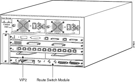
The Catalyst RSM/VIP2 can be installed in any slot in a Catalyst 5000 family switch except the top slots, which contain the supervisor engines. The Catalyst RSM/VIP2 in a Catalyst 5000 family switch does not use interface processor slot numbering; therefore, slots are not numbered. The PA-4T+ can be installed into either port adapter slot 0 or slot 1 on a Catalyst RSM/VIP2. Figure 1-10 shows a Catalyst RSM/VIP2 with two port adapters installed.
Note ![]() The Catalyst 5500 switch has 13 slots. Slot 1 is reserved for the supervisor engine. If a redundant supervisor engine is used, it would go in slot 2; otherwise, slot 2 can be used for other modules. Slot 13 is a dedicated slot, reserved for the ATM Switch Processor (ASP) module. Refer to the Catalyst 5000 Series Route Switch Module Installation and Configuration Note for any additional slot restrictions for the Catalyst RSM/VIP2.
The Catalyst 5500 switch has 13 slots. Slot 1 is reserved for the supervisor engine. If a redundant supervisor engine is used, it would go in slot 2; otherwise, slot 2 can be used for other modules. Slot 13 is a dedicated slot, reserved for the ATM Switch Processor (ASP) module. Refer to the Catalyst 5000 Series Route Switch Module Installation and Configuration Note for any additional slot restrictions for the Catalyst RSM/VIP2.
Figure 1-10 Catalyst 5000 Family Switch with Port Adapters Installed on Catalyst RSM/VIP2
Catalyst 6000 Family FlexWAN Module Slot Numbering
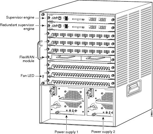
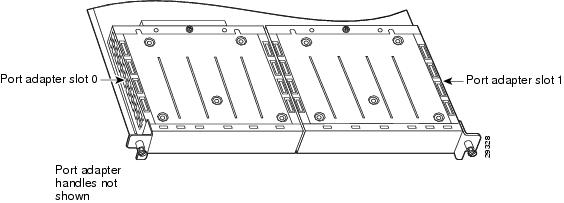
The Catalyst 6000 family FlexWAN module can be installed in any slot in a Catalyst 6000 family switch except slot 1, which is reserved for the supervisor engine. The PA-4T+ can be installed into either port adapter bay 0 or bay 1 on a FlexWAN module. Figure 1-11 shows a FlexWAN module with two blank port adapters installed.
Note ![]() Slot 1 is reserved for the supervisor engine. If a redundant supervisor engine is used, it would go in slot 2; otherwise, slot 2 can be used for other modules.
Slot 1 is reserved for the supervisor engine. If a redundant supervisor engine is used, it would go in slot 2; otherwise, slot 2 can be used for other modules.
Figure 1-11 Catalyst 6000 Family Switch with Port Adapters Installed on FlexWAN Module
Cisco 7100 Series Routers Slot Numbering
The PA-4T+ can be installed in port adapter slot 3 in Cisco 7120 series routers, and in port adapter slot 4 in Cisco 7140 series routers. Figure 1-12 shows the slot numbering on a Cisco 7120 series router. Figure 1-13 shows the slot numbering on a Cisco 7140 series router.
Figure 1-12 Port Adapter Slots in the Cisco 7120 Series Router
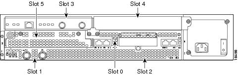
Figure 1-13 Port Adapter Slots in the Cisco 7140 Series Router
Cisco 7200 Series Routers and Cisco 7200 VXR Routers Slot Numbering
Cisco 7202 routers have two port adapter slots. The slots are numbered from left to right. You can place a port adapter in either of the slots (slot 1 or slot 2). The Cisco 7202 router is not shown.
Cisco 7204 routers and Cisco 7204VXR routers have four slots for port adapters, and one slot for an input/output (I/O) controller. The slots are numbered from the lower left to the upper right, beginning with slot 1 and continuing through slot 4. You can place a port adapter in any of the slots (slot 1 through slot 4). Slot 0 is always reserved for the I/O controller. The Cisco 7204 router and Cisco 7204VXR router are not shown.
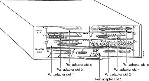
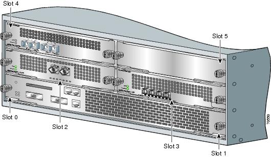
Cisco 7206 routers and Cisco 7206VXR routers (including the Cisco 7206 and Cisco 7206VXR as router shelves in a Cisco AS5800 Universal Access Server) have six slots for port adapters, and one slot for an input/output (I/O) controller. The slots are numbered from the lower left to the upper right, beginning with slot 1 and continuing through slot 6. You can place a port adapter in any of the six slots (slot 1 through slot 6). Slot 0 is always reserved for the I/O controller. Figure 1-14 shows the slot numbering on a Cisco 7206 router. The Cisco 7206VXR router is not shown.
Figure 1-14 Port Adapter Slots in the Cisco 7206 Router
Cisco uBR7200 Series Router Slot Numbering
The Cisco uBR7223 router has one port adapter slot (slot 1). Slot 0 is always reserved for the I/O controller—if present. The Cisco uBR7223 router is not shown.
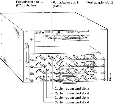
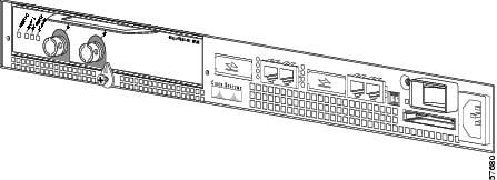
The Cisco uBR7246 router and Cisco uBR7246VXR router have two port adapter slots (slot1 and slot 2). Slot 0 is always reserved for the I/O controller—if present. Figure 1-15 shows the slot numbering of port adapters on a Cisco uBR7246 router or Cisco uBR7246VXR router.
Figure 1-15 Port Adapter Slots in the Cisco uBR7246 and Cisco uBR7246VXR Routers
Cisco 7201 Router Slot Numbering
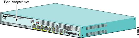
Figure 1-16 shows the front view of a Cisco 7201 router with a port adapter installed. There is only one port adapter slot (slot 1)in a Cisco 7201 router.
Figure 1-16 Port Adapter Slot in the Cisco 7201 Router
Cisco 7301 Router Slot Numbering
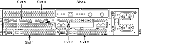
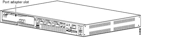
Figure 1-17 shows the front view of a Cisco 7301 router with a port adapter installed. There is only one port adapter slot (slot 1) in a Cisco 7301 router.
Figure 1-17 Port Adapter Slot in a Cisco 7301 Router
Cisco 7304 PCI Port Adapter Carrier Card Slot Numbering
The Cisco 7304 PCI Port Adapter Carrier Card installs in Cisco 7304 router module slots 2 through 5. Figure 1-18 shows a Cisco 7304 PCI Port Adapter Carrier Card with a port adapter installed. The Cisco 7304 PCI Port Adapter Carrier Card accepts one single-width port adapter.
Figure 1-19 shows the module slot numbering on a Cisco 7304 router. The port adapter slot number is the same as the module slot number. Slot 0 and slot 1 are reserved for the NPE module or NSE module
Figure 1-18 Cisco 7304 PCI Port Adapter Carrier Card—Port Adapter Installed
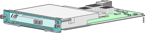
Figure 1-19 Module Slots on the Cisco 7304 Router
Cisco 7401ASR Router Slot Numbering
Figure 1-20 shows the front view of a Cisco 7401ASR router with a port adapter installed. There is only one port adapter slot (slot 1) in a Cisco 7401ASR router.
Figure 1-20 Port Adapter Slot in the Cisco 7401ASR Router
Cisco 7000 Series Routers and Cisco7500 Series Routers VIP Slot Numbering
Port adapters are supported on the VIPs (versatile interface processors) used in Cisco 7000 series and Cisco 7500 series routers. In the Cisco 7010 router and Cisco 7505 router, the VIP motherboard is installed horizontally in the VIP slot. In the Cisco 7507 router and Cisco 7513 router, the VIP motherboard is installed vertically in the VIP slot. A port adapter can be installed in either bay (port adapter slot 0 or 1) on the VIP. The bays are numbered from left to right on the VIP. Figure 1-21 shows the slot numbering on a VIP.
Figure 1-21 VIP Slot Locations—Horizontal Orientation
Cisco 7010 routers have three slots for port adapters, and two slots for Route Switch Processors (RSPs). The slots are numbered from bottom to top. You can place a port adapter in any of the VIP interface slots (slot 0 through 2). Slots 3 and 4 are always reserved for RSPs. The Cisco 7010 router is not shown.
Cisco 7505 routers have four slots for port adapters, and one slot for an RSP. The slots are numbered from bottom to top. You can place a port adapter in any of the VIP interface slots (slot 0 through 3). One slot is always reserved for the RSP. Figure 1-22 shows the slot numbering on a Cisco 7505 router.
Figure 1-22 VIP Slots in the Cisco 7505 Router
Cisco 7507 routers have five slots for port adapters, and two slots for RSPs. The slots are numbered from left to right. You can place a port adapter in any of the VIP interface slots (slot 0, 1, 4, 5, or 6). Slots 2 and 3 are always reserved for RSPs. The Cisco 7507 router is not shown.
Cisco 7513 routers have eleven slots for port adapters, and two slots for RSPs. The slots are numbered from left to right. You can place a port adapter in any of the VIP interface slots (slots 0 through 5, or slots 9 through 12). Slots 6 and 7 are always reserved for RSPs. The Cisco 7513 router is not shown.
Identifying Interface Addresses
This section describes how to identify interface addresses for the PA-4T+ in supported platforms. Interface addresses specify the actual physical location of each interface on a router or switch.
Interfaces on a PA-4T+ installed in a router maintain the same address regardless of whether other port adapters are installed or removed. However, when you move a port adapter to a different slot, the first number in the interface address changes to reflect the new port adapter slot number.
Interfaces on a PA-4T+ installed in a VIP or FlexWAN module maintain the same address regardless of whether other interface processors or modules are installed or removed. However, when you move a VIP or FlexWAN module to a different slot, the interface processor or module slot number changes to reflect the new interface processor or module slot.
Note ![]() Interface ports are numbered from left to right starting with 0.
Interface ports are numbered from left to right starting with 0.
The following subsections describe the interface address formats for the supported platforms:
•![]() Catalyst RSM/VIP2 Interface Addresses
Catalyst RSM/VIP2 Interface Addresses
•![]() Catalyst 6000 Family FlexWAN Module
Catalyst 6000 Family FlexWAN Module
•![]() Cisco 7100 Series Routers Interface Addresses
Cisco 7100 Series Routers Interface Addresses
•![]() Cisco 7200 Series Routers and Cisco 7200 VXR Routers Interface Addresses
Cisco 7200 Series Routers and Cisco 7200 VXR Routers Interface Addresses
•![]() Cisco uBR7200 Series Routers Interface Addresses
Cisco uBR7200 Series Routers Interface Addresses
•![]() Cisco 7201 Router Interface Addresses
Cisco 7201 Router Interface Addresses
•![]() Cisco 7301 Router Interface Addresses
Cisco 7301 Router Interface Addresses
•![]() Cisco 7304 PCI Port Adapter Carrier Card Interface Addresses
Cisco 7304 PCI Port Adapter Carrier Card Interface Addresses
•![]() Cisco 7401ASR Router Interface Addresses
Cisco 7401ASR Router Interface Addresses
•![]() Cisco 7000 Series Routers and Cisco 7500 Series Routers VIP Interface Addresses
Cisco 7000 Series Routers and Cisco 7500 Series Routers VIP Interface Addresses
Table 1-9 summarizes the interface address formats for the supported platforms.
|
|
|
|
|
|---|---|---|---|
Catalyst RSM/VIP2 in Catalyst 5000 family switches |
Port-adapter-slot-number/interface-port-number |
Port adapter slot— 0 or 1 Interface port—0 through 3 |
0/1 |
Catalyst 6000 family FlexWAN module in Catalyst 6000 family switches |
Module-slot-number/port-adapter-bay-number/ |
Module slot —21 through 13 (depends on the number of slots in the switch) Port adapter bay— 0 or 1 Interface port—0 through 3 |
3/0/0 |
Cisco 7120 series router |
Port-adapter-slot-number/interface-port-number |
Port adapter slot—always 3 Interface port—0 through 3 |
3/1 |
Cisco 7140 series router |
Port-adapter-slot-number/interface-port-number |
Port adapter slot—always 4 Interface port—0 through 3 |
4/0 |
Cisco 7200 series routers and Cisco 7200 VXR routers |
Port-adapter-slot-number/interface-port-number |
Port adapter slot—1 through 6 (depends on the number of slots in the router)2 Interface port—0 through 3 |
1/0 |
Cisco 7201 router |
Port-adapter-slot-number/interface-port-number |
Port adapter slot—always 1 Interface port—0 through 3 |
1/0 |
Cisco uBR7223 router |
Port-adapter-slot-number/interface-port-number |
Port adapter slot—always 12 Interface port—0 through 3 |
1/0 |
Cisco uBR7246 and Cisco uBR7246VXR routers |
Port-adapter-slot-number/interface-port-number |
Port adapter slot—1 or 22 Interface port—0 through 3 |
1/2 |
Cisco 7301 router |
Port-adapter-slot-number/interface-port-number |
Port adapter slot—always 1 Interface port—0 through 3 |
1/0 |
Cisco 7304 PCI Port Adapter Carrier Card in Cisco 7304 router |
Module-slot-number/interface-port-number |
Module slot— 2 through 5 Interface port—0 through 3 |
3/0 |
Cisco 7401ASR router |
Port-adapter-slot-number/interface-port-number |
Port adapter slot—always 1 Interface port—0 through 3 |
1/0 |
VIP in Cisco 7000 series routers or Cisco 7500 series routers |
Interface-processor-slot-number/port-adapter- |
Interface processor slot—0 through 12 (depends on the number of slots in the router) Port adapter slot— 0 or 1 Interface port—0 through 3 |
3/1/0 |
1 Slot 1 is reserved for the supervisor engine. If a redundant supervisor engine is used, it must go in slot 2; otherwise, slot 2 can be used for other modules. 2 Port adapter slot 0 is reserved for the Fast Ethernet port on the I/O controller (if present). |
Catalyst RSM/VIP2 Interface Addresses
In Catalyst 5000 family switches, the Catalyst RSM/VIP2 can be installed in any slot except the top slots, which contain the supervisor engine modules. The Catalyst RSM/VIP2 in a Catalyst 5000 family switch does not use interface processor slot numbering; therefore, the slots in which it is installed are not numbered. A port adapter can be installed into either port adapter slot 0 or slot 1 on a Catalyst RSM/VIP2. See Figure 1-10.
The interface address is composed of a two-part number in the format port-adapter-slot number/interface-port number. See Table 1-9.
For example, if the four-port PA-4T+ is installed in a VIP in interface processor slot 1, port adapter slot 1, the interface addresses would be 1/1/0, 1/1/1, 1/1/2, and 1/1/3 (interface processor slot 1, port adapter slot 1, and interfaces 0,1, 2, and 3).
Catalyst 6000 Family FlexWAN Module
In Catalyst 6000 family switches, the Catalyst 6000 family FlexWAN module can be installed in module slots 2 through 13 (depending on the number of slots in the router). Slot 1 is reserved for the supervisor engine. A port adapter can be installed into either port adapter bay 0 or bay 1 on a FlexWAN module. See Figure 1-11.
The interface address is composed of a three-part number in the format module-number/port-adapter-bay-number/interface-port-number. See Table 1-9.
The first number identifies the module slot of the chassis in which the FlexWAN module is installed (slot 2 through slot 3, 6, 9, or 13 depending on the number of slots in the chassis). These module slots are generally numbered from top to bottom, starting with 1.
The second number identifies the bay of the FlexWAN module in which the port adapter is installed (0 or 1). The bays are numbered from left to right on the FlexWAN module.
The third number identifies the physical port number on the port adapter. The PA-4T+ is a four-port port adapter, therefore the port can be 0 through 3.
For example, if a four-port PA-4T+ is installed in a FlexWAN module in module slot 3, port adapter bay 0, then the interface addresses are 3/0/0 through 3/0/3 (module slot 3, port adapter bay 0, and interfaces 0 through 3). If the port adapter was in port adapter bay 1 on the FlexWAN module, these same interface addresses would be numbered 3/1/0 through 3/1/3
Note ![]() The FlexWAN module physical port address begins with slot 0, which differs from the conventional Catalyst 6000 family port address, which begins with slot 1.
The FlexWAN module physical port address begins with slot 0, which differs from the conventional Catalyst 6000 family port address, which begins with slot 1.
Cisco 7100 Series Routers Interface Addresses
In Cisco 7120 series router, port adapters are installed in port adapter slot 3. See Figure 1-12. In the Cisco 7140 series router, port adapters are installed in port adapter slot 4. See Figure 1-13.
The interface address is composed of a two-part number in the format port-adapter-slot-number/interface-port-number. See Table 1-9. For example, if a four-port PA-4T+ is installed on a Cisco 7120 router, the interface addresses would be 3/0 through 3/3. If a four-port PA-4E1G is installed on a Cisco 7140 router, the interface addresses would be 4/0 through 4/3.
Cisco 7200 Series Routers and Cisco 7200 VXR Routers Interface Addresses
In Cisco 7200 series routers and Cisco 7200 VXR routers, port adapter slots are numbered from the lower left to the upper right, beginning with slot 1 and continuing through slot 2 for the Cisco 7202, slot 4 for the Cisco 7204 and Cisco 7204VXR, and slot 6 for the Cisco 7206 and Cisco 7206VXR. Port adapters can be installed in any available port adapter slot from 1 through 6 (depending on the number of slots in the router). (Slot 0 is reserved for the I/O controller.) See Figure 1-14.
The interface address is composed of a two-part number in the format port-adapter-slot-number/interface-port-number. See Table 1-9. For example, if a four-port PA-4T+ is installed in slot 1of a Cisco 7200 series router, the interface addresses would be 1/0 through 1/3.
Cisco uBR7200 Series Routers Interface Addresses
In the Cisco uBR7223 router, only one slot accepts port adapters and it is numbered slot 1.
In the Cisco uBR7246 router and Cisco uBR7246VXR router, port adapters can be installed in two port adapter slots (slot1 and slot 2). Slot 0 is always reserved for the I/O controller—if present. See Figure 1-15.
The interface address is composed of a two-part number in the format port-adapter-slot-number/interface-port-number. See Table 1-9. For example, if a four-port PA-4T+ is installed in slot 1of a Cisco uBR7223 series router, the interface addresses would be 1/0 through 1/3. If a four-port PA-4T+ is installed in slot 2 of a Cisco uBR7246 or Cisco uBR7246VXR router, the interface addresses would be 2/0 through 2/3.
Cisco 7201 Router Interface Addresses
In the Cisco 7201 router, only one slot accepts port adapters and it is numbered as slot 1. See Figure 1-16.
The interface address is composed of a two-part number in the format port-adapter-slot-number/interface-port-number. See Table 1-9. For example, if a four-port PA-4T+ is installed in a Cisco 7201 router, the interface addresses would be 1/0 through 1/3.
Cisco 7301 Router Interface Addresses
In the Cisco 7301 router, only one slot accepts port adapters and it is numbered as slot 1. See Figure 1-17.
The interface address is composed of a two-part number in the format port-adapter-slot-number/interface-port-number. See Table 1-9. For example, if a four-port PA-4T+ is installed in a Cisco 7301 router, the interface addresses would be 1/0 through 1/3.
Cisco 7304 PCI Port Adapter Carrier Card Interface Addresses
In the Cisco 7304 router, port adapters are installed in a Cisco 7304 PCI port adapter carrier card, which installs in Cisco 7304 router module slots 2 through 5. The port adapter slot number is the same as the module slot number. See Figure 1-18 and Figure 1-19.
The interface address is composed of a two-part number in the format module-slot-number/interface-port-number. See Table 1-9. For example, if a four-port PA-4T+ is installed in the Cisco 7304 PCI port adapter carrier card in Cisco 7304 router module slot 3, the interface addresses would be 3/0 through 3/3.
Cisco 7401ASR Router Interface Addresses
In the Cisco 7401ASR router, only one slot accepts port adapters and it is numbered as slot 1. See Figure 1-20.
The interface address is composed of a two-part number in the format port-adapter-slot-number/interface-port-number. See Table 1-9. For example, if a four-port PA-4T+ is installed in a Cisco 7401ASR router, the interface addresses would be 1/0 through 1/3.
Cisco 7000 Series Routers and Cisco 7500 Series Routers VIP Interface Addresses
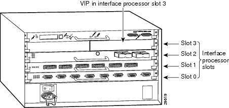
In Cisco 7000 series routers and Cisco 7500 series routers, port adapters are installed on a versatile interface processor (VIP), which installs in interface processor slots 0 through 12 (depending on the number of slots in the router). The port adapter can be installed in either bay (port adapter slot 0 or 1) on the VIP. See Figure 1-21, and Figure 1-22.
The interface address for the VIP is composed of a three-part number in the format interface-processor-slot-number/port-adapter-slot-number/interface-port-number. See Table 1-9.
The first number identifies the slot in which the VIP is installed (slot 0 through 12, depending on the number of slots in the router).
The second number identifies the bay (port adapter slot) on the VIP in which the port adapter is installed (0 or 1). The bays are numbered from left to right on the VIP.
The third number identifies the physical port number (interface port number) on the port adapter. The port numbers always begin at 0 and are numbered from left to right. The number of additional ports depends on the number of ports on the port adapter. The PA-4T+ is a four-port port adapter, therefore the port can be 0 through 3.
For example, if a four-port PA-4T+ is installed in a VIP in interface processor slot 3, port adapter slot 1, the interface addresses would be 3/1/0 through 3/1/3 (interface processor slot 3, port adapter slot 1, and interfaces 0, 1, 2 and3).
Note ![]() Although the processor slots in the 7-slot Cisco 7000 router and Cisco 7507router and the 13-slot Cisco 7513 router and Cisco 7576 router are vertically oriented and those in the 5-slot Cisco 7010 router and Cisco 7505 router are horizontally oriented, all Cisco 7000 series routers and Cisco 7500 series routers use the same method for slot and port numbering.
Although the processor slots in the 7-slot Cisco 7000 router and Cisco 7507router and the 13-slot Cisco 7513 router and Cisco 7576 router are vertically oriented and those in the 5-slot Cisco 7010 router and Cisco 7505 router are horizontally oriented, all Cisco 7000 series routers and Cisco 7500 series routers use the same method for slot and port numbering.
 Feedback