PA-4E1G Serial Port Adapter Installation and Configuration
Bias-Free Language
The documentation set for this product strives to use bias-free language. For the purposes of this documentation set, bias-free is defined as language that does not imply discrimination based on age, disability, gender, racial identity, ethnic identity, sexual orientation, socioeconomic status, and intersectionality. Exceptions may be present in the documentation due to language that is hardcoded in the user interfaces of the product software, language used based on RFP documentation, or language that is used by a referenced third-party product. Learn more about how Cisco is using Inclusive Language.
- Updated:
- September 14, 2007
Chapter: Removing and Installing the PA-4E1G
- Handling Port Adapters
- Online Insertion and Removal
- Warnings and Cautions
- Port Adapter Removal and Installation
- Cisco 7100 Series Routers—Removing and Installing a Port Adapter
- Cisco 7200 Series Routers and Cisco 7200 VXR Routers—Removing and Installing a Port Adapter
- Cisco uBR7200 Series Routers—Removing a Port Adapter
- Cisco uBR7200 Series Routers—Installing a Port Adapter
- Cisco 7201 Router—Removing and Installing a Port Adapter
- Cisco 7301 Router—Removing and Installing a Port Adapter
- Cisco 7304 PCI Port Adapter Carrier Card—Removing and Installing a Port Adapter
- Cisco 7401ASR Router—Removing and Installing a Port Adapter
- Cisco 7000 Series Routers and Cisco 7500 Series Routers with VIP—Removing and Installing a Port Adapter
- Installing Interface Cables
Removing and Installing Port Adapters
This chapter describes how to remove the PA-4E1G port adapter from supported platforms and also how to install a new or replacement port adapter. This chapter contains the following sections:
•![]() Port Adapter Removal and Installation
Port Adapter Removal and Installation
Handling Port Adapters
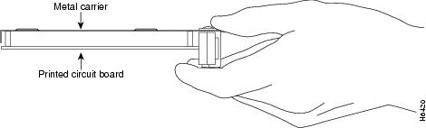
Each port adapter circuit board is mounted to a metal carrier and is sensitive to electrostatic discharge (ESD) damage.

Note ![]() When a slot is not in use, a blank port adapter must fill the empty slot to allow the router or switch to conform to electromagnetic interference (EMI) emissions requirements and to allow proper airflow across the installed port adapters. If you plan to install a new port adapter in a slot that is not in use, you must first remove the blank port adapter.
When a slot is not in use, a blank port adapter must fill the empty slot to allow the router or switch to conform to electromagnetic interference (EMI) emissions requirements and to allow proper airflow across the installed port adapters. If you plan to install a new port adapter in a slot that is not in use, you must first remove the blank port adapter.

Figure 3-1 Handling a Port Adapter
Online Insertion and Removal
Several platforms support online insertion and removal (OIR) of port adapters; therefore, you do not have to power down routers when removing and replacing a PA-4E1G in the Cisco 7100 series routers, Cisco 7200 series routers, Cisco 7200 VXR routers, Cisco uBR7200 series routers, Cisco 7201 router, Cisco 7301 router, or Cisco 7401ASR router.
Although the Cisco 7304 PCI port adapter carrier card and VIP support OIR, individual port adapters do not. To replace port adapters, you must first remove the Cisco 7304 PCI port adapter carrier card or VIP from the chassis and then install or replace port adapters as required. If a blank port adapter is installed on the Cisco 7304 PCI port adapter carrier card or VIP on which you want to install a new port adapter, you must first remove the Cisco 7304 PCI port adapter carrier card or VIP from the chassis and then remove the blank port adapter.
Note ![]() As you disengage the port adapter from the router or switch, OIR administratively shuts down all active interfaces in the port adapter.
As you disengage the port adapter from the router or switch, OIR administratively shuts down all active interfaces in the port adapter.
Warnings and Cautions
Observe the following warnings and cautions when installing or removing port adapters:
•![]() Do not slide a port adapter all the way into the slot until you have connected all required cables. Trying to do so disrupts normal operation of the router or switch.
Do not slide a port adapter all the way into the slot until you have connected all required cables. Trying to do so disrupts normal operation of the router or switch.
•![]() If a port adapter lever or other retaining mechanism does not move to the locked position, the port adapter is not completely seated in the midplane. Carefully pull the port adapter halfway out of the slot, reinsert it, and move the port adapter lever or other mechanism to the locked position.
If a port adapter lever or other retaining mechanism does not move to the locked position, the port adapter is not completely seated in the midplane. Carefully pull the port adapter halfway out of the slot, reinsert it, and move the port adapter lever or other mechanism to the locked position.
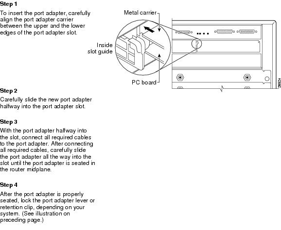
•![]() To prevent jamming the carrier between the upper and the lower edges of the port adapter slot, and to ensure that the edge connector at the rear of the port adapter mates with the connection at the rear of the port adapter slot, make certain that the carrier is positioned correctly, as shown in the cutaway illustrations in the "Port Adapter Removal and Installation" section.
To prevent jamming the carrier between the upper and the lower edges of the port adapter slot, and to ensure that the edge connector at the rear of the port adapter mates with the connection at the rear of the port adapter slot, make certain that the carrier is positioned correctly, as shown in the cutaway illustrations in the "Port Adapter Removal and Installation" section.
Note ![]() Before you begin installation, read Chapter 2, "Preparing for Installation," for a list of parts and tools required for installation.
Before you begin installation, read Chapter 2, "Preparing for Installation," for a list of parts and tools required for installation.

Warning ![]() When performing the following procedures, wear a grounding wrist strap to avoid ESD damage to the card. Some platforms have an ESD connector for attaching the wrist strap. Do not directly touch the midplane or backplane with your hand or any metal tool, or you could shock yourself.
When performing the following procedures, wear a grounding wrist strap to avoid ESD damage to the card. Some platforms have an ESD connector for attaching the wrist strap. Do not directly touch the midplane or backplane with your hand or any metal tool, or you could shock yourself.
Port Adapter Removal and Installation
In this section, the illustrations that follow give step-by-step instructions on how to remove and install port adapters. Although the procedures may refer to a particular type of port adapter, the steps are the same for installing and removing all types of port adapters. This section contains the following illustrations:
•![]() Cisco 7100 Series Routers—Removing and Installing a Port Adapter
Cisco 7100 Series Routers—Removing and Installing a Port Adapter
•![]() Cisco 7200 Series Routers and Cisco 7200 VXR Routers—Removing and Installing a Port Adapter
Cisco 7200 Series Routers and Cisco 7200 VXR Routers—Removing and Installing a Port Adapter
•![]() Cisco uBR7200 Series Routers—Removing a Port Adapter
Cisco uBR7200 Series Routers—Removing a Port Adapter
•![]() Cisco uBR7200 Series Routers—Installing a Port Adapter
Cisco uBR7200 Series Routers—Installing a Port Adapter
•![]() Cisco 7201 Router—Removing and Installing a Port Adapter
Cisco 7201 Router—Removing and Installing a Port Adapter
•![]() Cisco 7301 Router—Removing and Installing a Port Adapter
Cisco 7301 Router—Removing and Installing a Port Adapter
•![]() Cisco 7304 PCI Port Adapter Carrier Card—Removing and Installing a Port Adapter
Cisco 7304 PCI Port Adapter Carrier Card—Removing and Installing a Port Adapter
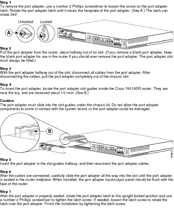
•![]() Cisco 7401ASR Router—Removing and Installing a Port Adapter
Cisco 7401ASR Router—Removing and Installing a Port Adapter
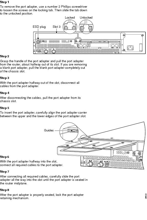
Cisco 7100 Series Routers—Removing and Installing a Port Adapter
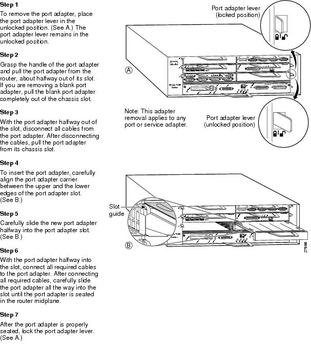
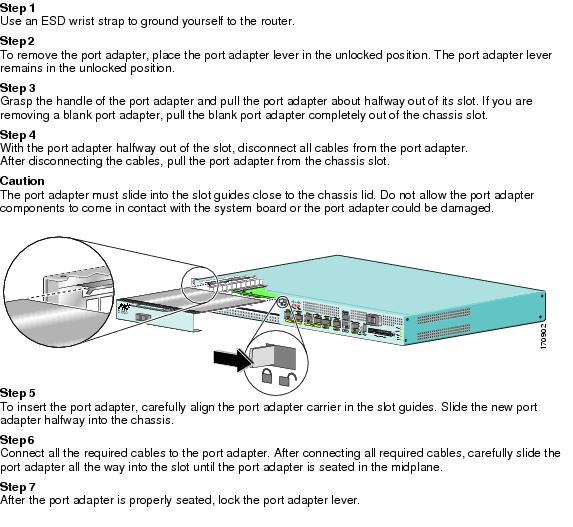
Cisco 7200 Series Routers and Cisco 7200 VXR Routers—Removing and Installing a Port Adapter
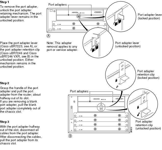
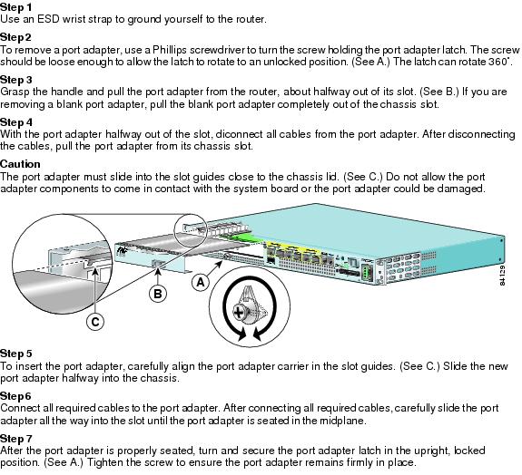
Cisco uBR7200 Series Routers—Removing a Port Adapter
Cisco uBR7200 Series Routers—Installing a Port Adapter
Cisco 7201 Router—Removing and Installing a Port Adapter
Cisco 7301 Router—Removing and Installing a Port Adapter
Cisco 7304 PCI Port Adapter Carrier Card—Removing and Installing a Port Adapter
You can install one single-width port adapter in a Cisco 7304 PCI Port Adapter Carrier Card. This section provides step-by-step instructions for removing and installing a port adapter in a Cisco 7304 PCI Port Adapter Carrier Card.
Warning ![]() When performing the following procedures, wear a grounding wrist strap to avoid ESD damage to the Cisco 7304 PCI Port Adapter Carrier Card. Some platforms have an ESD connector for attaching the wrist strap. Do not directly touch the midplane or backplane with your hand or any metal tool, or you could shock yourself.
When performing the following procedures, wear a grounding wrist strap to avoid ESD damage to the Cisco 7304 PCI Port Adapter Carrier Card. Some platforms have an ESD connector for attaching the wrist strap. Do not directly touch the midplane or backplane with your hand or any metal tool, or you could shock yourself.
To remove and install a port adapter in a Cisco 7304 PCI Port Adapter Carrier Card, refer to Figure 3-2 and do the following:
Step 1 ![]() If the Cisco 7304 PCI Port Adapter Carrier Card is still in the router, you must remove the Cisco 7304 PCI Port Adapter Carrier Card before removing a port adapter.
If the Cisco 7304 PCI Port Adapter Carrier Card is still in the router, you must remove the Cisco 7304 PCI Port Adapter Carrier Card before removing a port adapter.
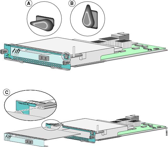
Step 2 ![]() To remove the port adapter from the Cisco 7304 PCI Port Adapter Carrier Card, turn the port adapter lock from its locked and horizontal position shown in A of Figure 3-2 to its unlocked and vertical position shown in B of Figure 3-2.
To remove the port adapter from the Cisco 7304 PCI Port Adapter Carrier Card, turn the port adapter lock from its locked and horizontal position shown in A of Figure 3-2 to its unlocked and vertical position shown in B of Figure 3-2.
Step 3 ![]() Grasp the handle of the port adapter and pull the port adapter from the Cisco 7304 PCI Port Adapter Carrier Card. (You have already disconnected the cables from the port adapter when removing the Cisco 7304 PCI Port Adapter Carrier Card).
Grasp the handle of the port adapter and pull the port adapter from the Cisco 7304 PCI Port Adapter Carrier Card. (You have already disconnected the cables from the port adapter when removing the Cisco 7304 PCI Port Adapter Carrier Card).
Step 4 ![]() To insert the port adapter in the Cisco 7304 PCI Port Adapter Carrier Card, locate the guide rails inside the Cisco 7304 PCI Port Adapter Carrier Card that hold the port adapter in place. They are at the top left and top right of the port adapter slot and are recessed about an inch, as shown in C of Figure 3-2.
To insert the port adapter in the Cisco 7304 PCI Port Adapter Carrier Card, locate the guide rails inside the Cisco 7304 PCI Port Adapter Carrier Card that hold the port adapter in place. They are at the top left and top right of the port adapter slot and are recessed about an inch, as shown in C of Figure 3-2.
Step 5 ![]() Carefully slide the port adapter in the Cisco 7304 PCI Port Adapter Carrier Card until the port adapter makes contact with the port adapter interface connector. When fully seated, the port adapter front panel should be flush with the face of the Cisco 7304 PCI Port Adapter Carrier Card.
Carefully slide the port adapter in the Cisco 7304 PCI Port Adapter Carrier Card until the port adapter makes contact with the port adapter interface connector. When fully seated, the port adapter front panel should be flush with the face of the Cisco 7304 PCI Port Adapter Carrier Card.
Step 6 ![]() After the port adapter is properly seated, turn the port adapter lock to its locked and horizontal position, as shown in A of Figure 3-2.
After the port adapter is properly seated, turn the port adapter lock to its locked and horizontal position, as shown in A of Figure 3-2.
Figure 3-2 illustrates how to remove and install a port adapter in a Cisco 7304 PCI Port Adapter Carrier Card.
Figure 3-2 Cisco 7304 PCI Port Adapter Carrier Card—Port Adapter Removal and Installation
Cisco 7401ASR Router—Removing and Installing a Port Adapter
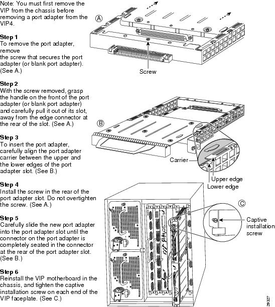
Cisco 7000 Series Routers and Cisco 7500 Series Routers with VIP—Removing and Installing a Port Adapter
Installing Interface Cables
To continue your PA-4E1G installation, you must install the port adapter cables. The instructions that follow apply to all supported platforms.
Use the following procedure to connect cables to the PA-4E1G in unbalanced mode:
Step 1 ![]() Attach the DB-15 end of a 75-ohm, unbalanced coaxial cable with BNC connector to the first DB-15 port you plan to use on the unbalanced, 75-ohm PA-4E1G.
Attach the DB-15 end of a 75-ohm, unbalanced coaxial cable with BNC connector to the first DB-15 port you plan to use on the unbalanced, 75-ohm PA-4E1G.
Step 2 ![]() Attach the network end of the 75-ohm, unbalanced coaxial cable to your external E1-G.703/G.704 equipment.
Attach the network end of the 75-ohm, unbalanced coaxial cable to your external E1-G.703/G.704 equipment.
Step 3 ![]() Repeat Steps 1 and 2 for each additional interface you plan to use on the port adapter.
Repeat Steps 1 and 2 for each additional interface you plan to use on the port adapter.
Use the following procedure to connect cables to the PA-4E1G in balanced mode:
Step 1 ![]() Attach the DB-15 end of one of the following types of cables to the first DB-15 port you plan to use on the balanced, 120-ohm PA-4E1G (see Figure 3-3):
Attach the DB-15 end of one of the following types of cables to the first DB-15 port you plan to use on the balanced, 120-ohm PA-4E1G (see Figure 3-3):
•![]() Balanced (120-ohm) cable with an RJ-45 connection at the network end
Balanced (120-ohm) cable with an RJ-45 connection at the network end
•![]() Balanced (120-ohm) cable with twinaxial connectors and cables at the network end
Balanced (120-ohm) cable with twinaxial connectors and cables at the network end
•![]() Balanced (120-ohm) cable with DB-15 connectors on both ends
Balanced (120-ohm) cable with DB-15 connectors on both ends
Step 2 ![]() Attach the network end of the 120-ohm, balanced cable to your external E1-G.703/G.704 equipment.
Attach the network end of the 120-ohm, balanced cable to your external E1-G.703/G.704 equipment.
Step 3 ![]() Repeat Steps 1 and 2 for each additional interface you plan to use on the port adapter.
Repeat Steps 1 and 2 for each additional interface you plan to use on the port adapter.
Figure 3-3 Connecting a PA-4E1G 120-Ohm DB-15 Cable—Front View (Shown Without Handle)
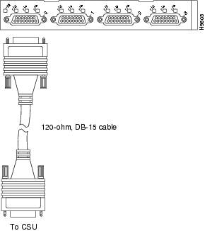
Note ![]() Port adapters have a handle attached, but this handle is not shown to allow a full view of detail on each port adapter's faceplate.
Port adapters have a handle attached, but this handle is not shown to allow a full view of detail on each port adapter's faceplate.
When attaching the cable receptacle on the PA-4E1G, use the cable-management bracket that shipped with your router for extra strain relief.
This completes the procedure for attaching a balanced or unbalanced cable to the PA-4E1G. Proceed to Chapter 4, "Configuring the PA-4E1G."
 Feedback