PA-POS-1OC3 Single-Port Port Adapter Installation and Configuration Guide
Bias-Free Language
The documentation set for this product strives to use bias-free language. For the purposes of this documentation set, bias-free is defined as language that does not imply discrimination based on age, disability, gender, racial identity, ethnic identity, sexual orientation, socioeconomic status, and intersectionality. Exceptions may be present in the documentation due to language that is hardcoded in the user interfaces of the product software, language used based on RFP documentation, or language that is used by a referenced third-party product. Learn more about how Cisco is using Inclusive Language.
- Updated:
- April 12, 2007
Chapter: Configuration
- Using the EXEC Command Interpreter
- Configuring the Interfaces
- Customizing the Configuration
- Checking the Configuration
Configuring the PA-POS-1OC3
The following instructions apply to all supported platforms. Minor differences among the platforms—with Cisco IOS software commands—are noted.
This chapter contains the following sections:
•![]() Using the EXEC Command Interpreter
Using the EXEC Command Interpreter
•![]() Customizing the Configuration
Customizing the Configuration
•![]() PA-POS-1OC3 Statistics Counters
PA-POS-1OC3 Statistics Counters
•![]() Making a Back-to-Back Connection
Making a Back-to-Back Connection
Using the EXEC Command Interpreter
You modify the configuration of your router through the software command interpreter called the EXEC (also called enable mode). You must enter the privileged level of the EXEC command interpreter with the enable command before you can use the configure command to configure a new interface or change the existing configuration of an interface. The system prompts you for a password if one has been set.
The system prompt for the privileged level ends with a pound sign (#) instead of an angle bracket (>). At the console terminal, use the following procedure to enter the privileged level:
Step 1 ![]() At the user-level EXEC prompt, enter the enable command. The EXEC prompts you for a privileged-level password.
At the user-level EXEC prompt, enter the enable command. The EXEC prompts you for a privileged-level password.
Router> enable
Password:
Step 2 ![]() Enter the password (the password is case sensitive). For security purposes, the password is not displayed. When you enter the correct password, the system displays the privileged-level system prompt (#).
Enter the password (the password is case sensitive). For security purposes, the password is not displayed. When you enter the correct password, the system displays the privileged-level system prompt (#).
Router#
To configure the new interfaces, proceed to the "Configuring the Interfaces" section.
Configuring the Interfaces
After you verify that the new PA-POS-1OC3 is installed correctly (the ENABLED LED goes on), use the privileged-level configure command to configure the new interfaces. Have the following information available:
•![]() IP addresses, if you plan to configure the interface for IP routing
IP addresses, if you plan to configure the interface for IP routing
•![]() MTU size
MTU size
•![]() Framing mode
Framing mode
•![]() Transmit clock source
Transmit clock source
•![]() Loopback modes (if testing is required)
Loopback modes (if testing is required)
If you installed a new PA-POS-1OC3 or if you want to change the configuration of an existing interface, you must enter configuration mode to configure the new interfaces. If you replaced a PA-POS-1OC3 that was previously configured, the system recognizes the new interfaces and brings each of them up in their existing configurations.
For a summary of the configuration options available and instructions for configuring the interfaces on a PA-POS-1OC3, refer to the appropriate configuration publications listed in the "Related Documentation" section on page iv.
You execute configuration commands from the privileged level of the EXEC command interpreter, which usually requires password access. (See the "Using the EXEC Command Interpreter" section for an explanation of the privileged level of the EXEC.) Contact your system administrator, if necessary, to obtain password access.
On power-up, the OC-3 interface on a new PA-POS-1OC3 is shut down. To enable the interfaces, you must enter the no shutdown command in configuration mode. (See "Performing a Basic Configuration" section.) When the OC-3 interface is enabled (taken out of shutdown) with no additional arguments, the default interface configuration file parameters look like those in Table 4-1.
|
|
|
|
|---|---|---|
MTU |
mtu bytes (no mtu bytes) |
4470 bytes |
Framing |
pos framing sdh (no pos framing sdh) |
SONET framing |
Loopback internal |
loop internal (no loop internal) |
No internal loopback |
Loopback line |
loop line (no loop line) |
No line loopback |
Transmit clocking source |
clock source internal |
No loop internal, |
Cyclic redundancy checks |
crc 16 |
crc 16 |
SONET payload scrambling |
pos scramble-atm |
No scrambling |
1 These default parameters apply to the PA-POS-1OC3 in all supported platforms. |
Shutting Down an Interface
Before you remove an interface that you will not replace, or replace port adapters, use the shutdown command to shut down (disable) the interfaces to prevent anomalies when you reinstall the new or reconfigured interface processor. When you shut down an interface, it is designated administratively down in the show command displays.
Follow these steps to shut down an interface:
Step 1 ![]() Enter the privileged level of the EXEC command interpreter (also called enable mode). (See the "Using the EXEC Command Interpreter" section for instructions.)
Enter the privileged level of the EXEC command interpreter (also called enable mode). (See the "Using the EXEC Command Interpreter" section for instructions.)
Step 2 ![]() At the privileged-level prompt, enter configuration mode and specify that the console terminal is the source of the configuration subcommands, as follows:
At the privileged-level prompt, enter configuration mode and specify that the console terminal is the source of the configuration subcommands, as follows:
Router# configure terminal
Enter configuration commands, one per line. End with CNTL/Z.
Router(config)#
Step 3 ![]() Shut down interfaces by entering the interface pos subcommand (followed by the interface address of the interface), and then enter the shutdown command.
Shut down interfaces by entering the interface pos subcommand (followed by the interface address of the interface), and then enter the shutdown command.
When you have finished, press Ctrl-Z—hold down the Control key while you press Z—or enter end or exit to exit the configuration mode and return to the EXEC command interpreter.
Table 4-2 shows the shutdown command syntax for the supported platforms.
|
|
|
|
|---|---|---|
Cisco 7200 VXR routers1 |
interface, followed by the type (pos) and slot/port (port-adapter-slot-number/ |
The example is for interface 0 on a port adapter in slot 6. Router(config-if)# interface pos 6/0
Router(config-if)# shutdown
Ctrl-Z
Router# |
Cisco 7201 router |
interface, followed by the type (pos) and slot/port (port-adapter-slot-number/ |
The example is for interface 0 on a port adapter in slot 1. Router(config-if)# interface pos 1/0
Router(config-if)# shutdown
Ctrl-Z
Router# |
Cisco 7301 router |
interface, followed by the type (pos) and slot/port (port-adapter-slot-number/ |
The example is for interface 0 on a port adapter in slot 1. Router(config-if)# interface pos 1/0
Router(config-if)# shutdown
Ctrl-Z
Router# |
Cisco 7304 PCI Port Adapter Carrier Card in a Cisco 7304 router |
interface, followed by the type (pos) and slot/port (module-slot-number/ |
The example is for interface 0 on a port adapter in a Cisco 7304 PCI Port Adapter Carrier Card in module slot 3 of a Cisco 7304 router. Router(config-if)# interface pos 3/0
Router(config-if)# shutdown
Ctrl-Z
Router#
|
Cisco 7401ASR router |
interface, followed by the type (pos) and slot/port (port-adapter-slot-number/ |
The example is for interface 0 on a port adapter in slot 1. Router(config-if)# interface pos 1/0
Router(config-if)# shutdown
Ctrl-Z
Router# |
VIP in the Cisco 7500 series routers (7505, 7507, 7513) |
interface, followed by the type (pos) slot/port-adapter/port (interface-processor-slot-number/ |
The example is for interface 0 in port adapter slot 1 of a VIP installed in interface processor slot 1. Router(config)# interface pos 1/1/0
Router(config-if)# shutdown
Ctrl-Z
Router# |
Cisco 7600 series routers (7603, 7606, 7609, 7613) with FlexWAN or Enhanced FlexWAN |
interface, followed by the type (pos) module/bay/port (module-slot-number/port-adapter-bay- |
The example is for interface 0 on a port adapter in port adapter bay 0 of a FlexWAN module in module slot 3. Router# interfaces pos 3/0/0 Router(config-if)# shutdown
Ctrl-Z
Router# |
1 For the Cisco 7206VXR router shelves in the Cisco AS5800, the interface specified in the above example would include a shelf number. For example, the command interface serial 5/3/0 specifies the OC-3 interface of the PA-POS-1OC3 in port adapter slot 3 of router shelf 5. |
Step 4 ![]() Write the new configuration to NVRAM as follows:
Write the new configuration to NVRAM as follows:
Router# copy running-config startup-config
[OK]
Router#
The system displays an OK message when the configuration has been stored in NVRAM.
Verify that new interfaces are now in the correct state (shut down) using the show interfaces command (followed by the interface type and interface address of the interface) to display the specific interface.
Table 4-3 provides examples of the show interfaces pos command for the supported platforms.
|
|
|
|
|---|---|---|
Cisco 7200 VXR routers1 |
show interfaces pos, followed by slot/port (port-adapter-slot-number/ interface-port-number) |
The example is for interface 0 on a port adapter in slot 6. Router# show interfaces pos 6/0
Pos 6/0 is administratively down, line
protocol is down
[Additional display text omitted from this example] |
Cisco 7201 router |
show interfaces pos, followed by slot/port (port-adapter-slot-number/ interface-port-number) |
The example is for interface 0 on a port adapter in slot 1. Router# show interfaces pos 1/0
Pos 1/0 is administratively down, line
protocol is down
[Additional display text omitted from this example] |
Cisco 7301 router |
show interfaces pos, followed by slot/port (port-adapter-slot-number/ interface-port-number) |
The example is for interface 0 on a port adapter in slot 1. Router# show interfaces pos 1/0
Pos 1/0 is administratively down, line
protocol is down
[Additional display text omitted from this example] |
Cisco 7304 PCI Port Adapter Carrier Card in a Cisco 7304 router |
show interfaces pos, followed by slot/port (module-slot-number/ |
The example is for interface 0 on a port adapter in a Cisco 7304 PCI Port Adapter Carrier Card in module slot 3 of a Cisco 7304 router. Router# show interfaces pos 3/0
Pos 3/0 is administratively down, line
protocol is down
[Additional display text omitted from this example] |
Cisco 7401ASR router |
show interfaces pos, followed by slot/port (port-adapter-slot-number/ interface-port-number) |
The example is for interface 0 on a port adapter in slot 1. Router# show interfaces pos 1/0
Pos 1/0 is administratively down, line
protocol is down
[Additional display text omitted from this example] |
VIP in the Cisco 7500 series routers (7505, 7507, 7513) |
show interfaces pos followed by slot/port-adapter/port (interface-processor-slot-number/ |
The example is for interface 0 in port adapter slot 1 of a VIP installed in interface processor slot 1. Router#show interface pos 1/1/0
Pos 1/1/0 is administratively down, line
protocol is down
[Additional display text omitted from this example] |
Cisco 7600 series routers (7603, 7606, 7609, 7613) with FlexWAN or Enhanced FlexWAN |
show interfaces pos followed by slot/port-adapter/port (module-slot-number/ port-adapter-bay-number/ interface-port-number) |
The example is for interface 0 on a port adapter in port adapter bay 0 of a FlexWAN module in module slot 3. Router# show interfaces pos 3/0/0 Pos 3/0/0 is administratively down, line protocol is down [Additional display text omitted from this example] |
1 For the Cisco 7206VXR router shelves in the Cisco AS5800, the interface specified in the above example would include a shelf number. For example, the command show interface 5/3/0 specifies the OC-3 interface of the PA-POS-1OC3 in port adapter slot 3 of router shelf 5. |
Step 5 ![]() Re-enable interfaces by doing the following:
Re-enable interfaces by doing the following:
a. ![]() Repeat Step 3 to re-enable an interface. Substitute the no shutdown command for the shutdown command.
Repeat Step 3 to re-enable an interface. Substitute the no shutdown command for the shutdown command.
b. ![]() Repeat Step 4 to write the new configuration to memory. Use the copy running-config startup-config command.
Repeat Step 4 to write the new configuration to memory. Use the copy running-config startup-config command.
c. ![]() Repeat to verify that the interfaces are in the correct state. Use the show interfaces command followed by the interface type and interface address of the interface.
Repeat to verify that the interfaces are in the correct state. Use the show interfaces command followed by the interface type and interface address of the interface.
Performing a Basic Configuration
Following are instructions for performing a basic configuration, which include enabling an interface (with the no shutdown command) and specifying IP routing. You might also need to enter other configuration commands, depending on the requirements for your system configuration and the protocols you plan to route on the interface.
For complete descriptions of configuration commands and the configuration options available for the interfaces of your port adapter, refer to the appropriate software documentation.
In the following procedure, press the Return key after each step unless otherwise noted. At any time, you can exit the privileged level and return to the user level by entering disable at the prompt as follows:
Router# disable
Router>
Step 1 ![]() Enter configuration mode and specify that the console terminal will be the source of the configuration subcommands as follows:
Enter configuration mode and specify that the console terminal will be the source of the configuration subcommands as follows:
Router# configure terminal
Enter configuration commands, one per line. End with CNTL/Z.
Router(config)#
Step 2 ![]() Specify the new interface to configure by entering the interface pos command, followed by the interface address of the interface you plan to configure.
Specify the new interface to configure by entering the interface pos command, followed by the interface address of the interface you plan to configure.
Table 4-4 provides example of the interface pos subcommand for the supported platforms.
|
|
|
|
|---|---|---|
Cisco 7200 VXR routers1 |
interface pos, followed by slot/port (port-adapter-slot-number/ |
This example is for interface 0 of a PA-POS-1OC3 in port adapter slot 6: Router(config)# interface pos 6/0 Router(config-if)# |
Cisco 7201 router |
interface pos, followed by slot/port (port-adapter-slot-number/ |
The example is for interface o of a PA-POS-1OC3 in port adapter slot 1: Router(config)# interface pos 1/0 Router(config-if)# |
Cisco 7301 router |
interface pos, followed by slot/port (port-adapter-slot-number/ |
The example is for interface o of a PA-POS-1OC3 in port adapter slot 1: Router(config)# interface pos 1/0 Router(config-if)# |
Cisco 7304 PCI Port Adapter Carrier Card in a Cisco 7304 router |
interface pos, followed by slot/port (module-slot-number/ |
The example is for interface 0 on a port adapter in a Cisco 7304 PCI Port Adapter Carrier Card in module slot 3 of a Cisco 7304 router. Router# interface pos 3/0
Router(config-if)# |
Cisco 7401ASR router |
interface pos, followed by slot/port (port-adapter-slot-number/ |
The example is for interface 0 of a PA-POS-1OC3 in port adapter slot 1: Router(config)# interface pos 1/0 Router(config-if)# |
VIPs in the Cisco 7500 series routers (7505, 7507, 7513) |
interface pos, followed by slot/port-adapter/port (interface-processor-slot-number/ |
The example is for interface 0 in port adapter slot 1 of a VIP installed in interface processor slot 1. Router(config)# interface pos 1/1/0
Router(config-if)# |
Cisco 7600 series routers (7603, 7606, 7609, 7613) with FlexWAN or Enhanced FlexWAN |
interface pos, followed by slot/port-adapter/port (module-slot-number/ port-adapter-bay-number/ interface-port-number) |
The example is for interface 0 on a port adapter in port adapter bay 0 of a FlexWAN module in module slot 3. Router# interface pos 3/0/0 Router(config-if)# |
1 For the Cisco 7206VXR router shelves in the Cisco AS5800, the interface specified in the above example would include a shelf number. For example, the command interface pos 5/3/0 specifies the OC-3 interface of the PA-POS-1OC3 in port adapter slot 3 of router shelf 5. |
Step 3 ![]() Assign an IP address and subnet mask to the interface (if IP routing is enabled on the system) by using the ip address configuration subcommand, as in the following example:
Assign an IP address and subnet mask to the interface (if IP routing is enabled on the system) by using the ip address configuration subcommand, as in the following example:
Router(config-if)# ip address 10.0.0.10 255.255.255.255
Step 4 ![]() Change the shutdown state to up and enable the interface as follows:
Change the shutdown state to up and enable the interface as follows:
Router(config-if)# no shutdown
The no shutdown command passes an enable command to the interface and causes the PA-POS-1OC3 to configure itself based on the previous configuration commands sent.
Step 5 ![]() Add any additional configuration subcommands required to enable routing protocols and set the interface characteristics.
Add any additional configuration subcommands required to enable routing protocols and set the interface characteristics.
Step 6 ![]() After including all of the configuration commands to complete your configuration, press Ctrl-Z—hold down the Control key while you press Z—or enter end or exit to exit configuration mode and return to the EXEC command interpreter prompt.
After including all of the configuration commands to complete your configuration, press Ctrl-Z—hold down the Control key while you press Z—or enter end or exit to exit configuration mode and return to the EXEC command interpreter prompt.
Step 7 ![]() Write the new configuration to NVRAM as follows:
Write the new configuration to NVRAM as follows:
Router# copy running-config startup-config
[OK]
Router#
This completes the procedure for creating a basic configuration. To check the interface configuration with show commands, proceed to the "Checking the Configuration" section.
Customizing the Configuration
You can customize the default values of all configuration parameters to match your network environment. Use the interface subcommands in the following sections if you need to customize the PA-POS-1OC3 configuration:
•![]() Setting the Source of the Transmit Clock
Setting the Source of the Transmit Clock
•![]() Configuring Cyclic Redundancy Checks
Configuring Cyclic Redundancy Checks
•![]() Configuring SONET Payload Scrambling
Configuring SONET Payload Scrambling
The interface subcommands that follow function the same regardless of the platform in which your PA-POS-1OC3 is installed; however, all these commands require that you first enter the interface pos command to select the interface that you want to configure. In all the configuration examples that follow, the interface address argument for the interface pos command is for a Cisco 7200 VXR router: 3/0 (port adapter slot 3, interface 0).
For the appropriate interface pos command syntax to use for your particular platform, see Table 4-4.
Setting the MTU Size

Note ![]() The default MTU size is 4470 bytes. The default value, 4470 bytes, exactly matches the maximum transmission unit (MTU) of the fiber distributed data interface (FDDI) and high-speed serial interface (HSSI) for autonomous switching.
The default MTU size is 4470 bytes. The default value, 4470 bytes, exactly matches the maximum transmission unit (MTU) of the fiber distributed data interface (FDDI) and high-speed serial interface (HSSI) for autonomous switching.
Step 1 ![]() To set the MTU size, enter the mtu bytes command, where bytes is a value in the range of 64 to 9216.
To set the MTU size, enter the mtu bytes command, where bytes is a value in the range of 64 to 9216.
Router(config)# interface pos 3/0
Router(config-if)# mtu 3000
Step 2 ![]() To restore the default of 4470 bytes, enter the no mtu command.
To restore the default of 4470 bytes, enter the no mtu command.
Router(config)# interface pos 3/0
Router(config-if)# no mtu 3000
Configuring Framing
The default framing setting is SONET STS-3c.
Step 1 ![]() To configure for SDH STM-1, enter the pos framing sdh command:
To configure for SDH STM-1, enter the pos framing sdh command:
Router(config)# interface pos 3/0
Router(config-if)# pos framing sdh
Step 2 ![]() To change back to SONET STS-3c, enter the no pos framing sdh command.
To change back to SONET STS-3c, enter the no pos framing sdh command.
Router(config)# interface pos 3/0
Router(config-if)# no pos framing sdh
Setting the Source of the Transmit Clock
The clocking default specifies that the PA-POS-1OC3 use the recovered receive (RX) clock to provide transmit (TX) clocking (called loop timing).
Note ![]() If line loopback is selected, the PA-POS-1OC3 is forced into loop timing mode until the loopback is disengaged.
If line loopback is selected, the PA-POS-1OC3 is forced into loop timing mode until the loopback is disengaged.
Step 1 ![]() To specify that the PA-POS-1OC3 generate the transmit clock internally, enter the clock source internal command:
To specify that the PA-POS-1OC3 generate the transmit clock internally, enter the clock source internal command:
Router(config)# interface pos 3/0
Router(config-if)# clock source internal
Step 2 ![]() To restore loop timing, enter the no clock source internal command or the clock source line command.
To restore loop timing, enter the no clock source internal command or the clock source line command.
Router(config)# interface pos 3/0
Router(config-if)# no clock source internal
Configuring Cyclic Redundancy Checks
The cyclic redundancy check (CRC) default is for a 16-bit CRC. The CRC is an error-checking technique that uses a calculated numeric value to detect errors in transmitted data. The PA-POS-1OC3 also supports a 32-bit CRC. The sender of a data frame calculates the frame check sequence (FCS). The sender appends the FCS value to outgoing messages. The receiver recalculates the FCS and compares it to the FCS from the sender. If a difference exists, the receiver assumes that a transmission error occurred and sends a request to the sender to resend the frame.
Step 1 ![]() To configure an interface for a 32-bit CRC, enter the crc 32 command:
To configure an interface for a 32-bit CRC, enter the crc 32 command:
Router(config)# interface pos 3/0
Router(config-if)# crc 32
Step 2 ![]() To disable the 32-bit CRC and return the interface to the default 16-bit CRC, enter the no crc 32 command.
To disable the 32-bit CRC and return the interface to the default 16-bit CRC, enter the no crc 32 command.
Router(config)# interface pos 3/0
Router(config-if)# no crc 32
Configuring SONET Payload Scrambling
The default is for SONET payload scrambling to be disabled. SONET payload scrambling applies a self-synchronous scrambler (x^43+1) to the Synchronous Payload Envelope (SPE) of the OC-3 interface to ensure sufficient bit-transition density.
Note ![]() Both ends of the connection must use the same scrambling algorithm.
Both ends of the connection must use the same scrambling algorithm.
You enable SONET payload scrambling using the pos scramble-atm command. (This command has no keywords or arguments.)
Step 1 ![]() To enable SONET payload scrambling, use the following command sequence:
To enable SONET payload scrambling, use the following command sequence:
Router(config)# interface pos 3/0
Router(config-if)# pos scramble-atm
Router(config-if)# no shutdown
Router(config-if)# end
Step 2 ![]() To verify that SONET payload scrambling is enabled on an interface, enter the show startup-config command. If scrambling is enabled, the following line is displayed in the configuration:
To verify that SONET payload scrambling is enabled on an interface, enter the show startup-config command. If scrambling is enabled, the following line is displayed in the configuration:
pos scramble-atm
Step 3 ![]() To disable SONET payload scrambling, use the no pos scramble-atm command.
To disable SONET payload scrambling, use the no pos scramble-atm command.
Router(config)# interface pos 3/0
Router(config-if)# no pos scramble-atm
Configuring APS
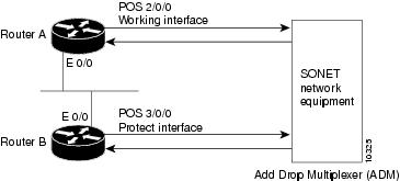
The following example shows the configuration of automatic protection switching (APS) on router A and router B. (See Figure 4-1.) In this example, router A is configured with the working interface, and router B is configured with the protect interface. If the working interface on router A becomes unavailable, the connection will automatically switch over to the protect interface on router B.
Figure 4-1 Basic APS Configuration
On router A, which contains the working interface, use the following configuration:
Router# configure terminal
Router(config)# interface loopback 1
Router(config-if)# ip address 10.7.7.7 255.255.255.0
Router(config)# interface pos 2/0/0
Router(config-if)# aps group 1
Router(config-if)# aps working 1
Router(config-if)# pos ais-shut
Router(config-if)# end
Router#
On router B, which contains the protect interface, use the following configuration:
Router# configure terminal
Router(config)# interface loopback 2
Router(config-if)# ip address 10.7.7.6 255.255.255.0
Router(config)# interface pos 3/0/0
Router(config-if)# aps group 1
Router(config-if)# aps protect 1 10.7.7.7
Router(config-if)# pos ais-shut
Router(config-if)# end
Router#
Note ![]() The loopback interface is used as the interconnect. The aps group command is used even when a single protect group is configured.
The loopback interface is used as the interconnect. The aps group command is used even when a single protect group is configured.
To verify the configuration or to determine if a switchover has occurred, use the show aps command.
For more information on SONET APS, see the following documents:
•![]() Automatic Protection Switching of Packet-over-SONET Circuits at the following URL:
Automatic Protection Switching of Packet-over-SONET Circuits at the following URL:
http://www.cisco.com/en/US/products/sw/iosswrel/ps1824/products_feature_guide09186a0080087ad9.html
•![]() Configuring Redundancy for POS/APS at the following URL:
Configuring Redundancy for POS/APS at the following URL:
http://www.cisco.com/warp/public/127/POS/pos-aps_14680.html
Checking the Configuration
After configuring the new interface, use show commands to display the status of the new interface or all interfaces, and use the ping and loopback commands to check connectivity. This section includes the following subsections:
•![]() Using show Commands to Verify the New Interface Status
Using show Commands to Verify the New Interface Status
•![]() Using the ping Command to Verify Network Connectivity
Using the ping Command to Verify Network Connectivity
For complete command descriptions and examples, refer to the publications listed in the "Related Documentation" section on page iv.
Using show Commands to Verify the New Interface Status
Table 4-5 demonstrates how you can use the show commands to verify that new interfaces are configured and operating correctly and that the PA-POS-1OC3 appears in them correctly. Sample displays of the output of selected show commands appear in the sections that follow.
Note ![]() The outputs that appear in this document may not match the output you receive when running these commands. The outputs in this document are examples only.
The outputs that appear in this document may not match the output you receive when running these commands. The outputs in this document are examples only.
If an interface is shut down and you configured it as up, or if the displays indicate that the hardware is not functioning properly, ensure that the interface is properly connected and terminated. If you still have problems bringing up the interface, contact a service representative for assistance.
This section includes the following subsections:
•![]() Using the show version or show hardware Commands
Using the show version or show hardware Commands
•![]() Using the show interfaces Command
Using the show interfaces Command
Choose the subsection appropriate for your system. Proceed to the "Using the ping Command to Verify Network Connectivity" section when you have finished using the show commands.
Using the show version or show hardware Commands
Display the configuration of the system hardware, the number of each interface type installed, the Cisco IOS software version, the names and sources of configuration files, and the boot images using the show version (or show hardware) command.
Note ![]() The outputs that appear in this document may not match the output you receive when running these commands. The outputs in this document are examples only.
The outputs that appear in this document may not match the output you receive when running these commands. The outputs in this document are examples only.
The following sections provide output of the show version command for some of the supported platforms:
•![]() Cisco 7200 VXR Routers—Example Output of the show version Command
Cisco 7200 VXR Routers—Example Output of the show version Command
•![]() Cisco 7201 Router—Example Output of the show version Command
Cisco 7201 Router—Example Output of the show version Command
•![]() Cisco 7301 Router—Example Output of the show version Command
Cisco 7301 Router—Example Output of the show version Command
•![]() VIP in Cisco 7500 Series Routers—Example Output of the show version Command
VIP in Cisco 7500 Series Routers—Example Output of the show version Command
Cisco 7200 VXR Routers—Example Output of the show version Command
Following is an example of the show version command from a Cisco 7206 VXR router with the PA-POS-1OC3 installed:
Router# show version
Cisco Internetwork Operating System Software
IOS (tm) 7200 Software (C7200-JS-M), Version 12.3(10), RELEASE SOFTWARE (fc3)
Copyright (c) 1986-2004 by cisco Systems, Inc.
Compiled Mon 16-Aug-04 23:46 by kellythw
Image text-base: 0x60008AF4, data-base: 0x62014000
ROM: System Bootstrap, Version 12.3(4r)T1, RELEASE SOFTWARE (fc1)
Router uptime is 3 minutes
System returned to ROM by power-on
System image file is "disk2:c7200-js-mz.123-10"
cisco 7206VXR (NPE-G1) processor (revision A) with 491520K/32768K bytes of memory.
Processor board ID 26813737
SB-1 CPU at 700MHz, Implementation 1, Rev 0.2, 512KB L2 Cache
6 slot VXR midplane, Version 2.6
Last reset from power-on
Bridging software.
X.25 software, Version 3.0.0.
SuperLAT software (copyright 1990 by Meridian Technology Corp).
TN3270 Emulation software.
PCI bus mb1 (Slots 1, 3 and 5) has a capacity of 600 bandwidth points.
Current configuration on bus mb1 has a total of 0 bandwidth points. This configuration is
within the PCI bus capacity and is supported.
PCI bus mb2 (Slots 2, 4 and 6) has a capacity of 600 bandwidth points.
Current configuration on bus mb2 has a total of 300 bandwidth points. This configuration
is within the PCI bus capacity and is supported.
Please refer to the following document "Cisco 7200 Series Port Adaptor Hardware
Configuration Guidelines" on CCO <www.cisco.com>, for c7200 bandwidth points
oversubscription/usage guidelines.
3 Gigabit Ethernet/IEEE 802.3 interface(s)
1 Packet over SONET network interface(s)
509K bytes of non-volatile configuration memory.
125184K bytes of ATA PCMCIA card at slot 2 (Sector size 512 bytes).
16384K bytes of Flash internal SIMM (Sector size 256K).
Configuration register is 0x0
Cisco 7201 Router—Example Output of the show version Command
Following is an example of the show version command from a Cisco 7201 router:
Router# show version
Cisco IOS Software, 7200 Software (C7200P-ADVENTERPRISEK9-M), Version
12.4(biffDEV.061001), INTERIM SOFTWARE Copyright (c) 1986-2006 by Cisco Systems, Inc.
Compiled Sun 01-Oct-06 23:42 by biff
ROM: System Bootstrap, Version 12.4(4r)XD5, RELEASE SOFTWARE (fc1)
BOOTLDR: Cisco IOS Software, 7200 Software (C7200P-KBOOT-M), Version 12.4(TAZ3DEV.060927),
INTERIM SOFTWARE
c7201alpha1 uptime is 5 days, 18 hours, 32 minutes System returned to ROM by power-on
System image file is "disk0:c7200p-adventerprisek9-mz.2006-10-01.biffdev"
This product contains cryptographic features and is subject to United States and local
country laws governing import, export, transfer and use. Delivery of Cisco cryptographic
products does not imply third-party authority to import, export, distribute or use
encryption.
Importers, exporters, distributors and users are responsible for compliance with U.S. and
local country laws. By using this product you agree to comply with applicable laws and
regulations. If you are unable to comply with U.S. and local laws, return this product
immediately.
A summary of U.S. laws governing Cisco cryptographic products may be found at:
http://www.cisco.com/wwl/export/crypto/tool/stqrg.html
If you require further assistance please contact us by sending email to export@cisco.com.
Cisco 7201 (c7201) processor (revision A) with 917504K/65536K bytes of memory.
Processor board ID 2222222222222
MPC7448 CPU at 1666Mhz, Implementation 0, Rev 2.2
1 slot midplane, Version 2.255
Last reset from power-on
1 FastEthernet interface
4 Gigabit Ethernet interfaces
2045K bytes of NVRAM.
62443K bytes of USB Flash usbflash0 (Read/Write)
250880K bytes of ATA PCMCIA card at slot 0 (Sector size 512 bytes).
65536K bytes of Flash internal SIMM (Sector size 512K).
Configuration register is 0x2
Cisco 7301 Router—Example Output of the show version Command
Following is an example of the show version command from a Cisco 7301 router with the PA-POS-1OC3 installed:
Router# show version
Cisco Internetwork Operating System Software
IOS (tm) 7301 Software (C7301-JS-M), Version 12.3(10), RELEASE SOFTWARE (fc3)
Copyright (c) 1986-2004 by cisco Systems, Inc.
Compiled Mon 16-Aug-04 22:00 by kellythw
Image text-base: 0x60008AF4, data-base: 0x61F8A000
ROM: System Bootstrap, Version 12.2(8r)B3, RELEASE SOFTWARE (fc1)
rac3-7301 uptime is 0 minutes
System returned to ROM by power-on
System image file is "disk0:c7301-js-mz.123-10"
cisco 7301 (NPE) processor (revision A) with 983040K/65536K bytes of memory.
Processor board ID 74998962
SB-1 CPU at 700MHz, Implementation 1, Rev 0.2, 512KB L2 Cache
1 slot midplane, Version 2.0
Last reset from power-on
Bridging software.
X.25 software, Version 3.0.0.
SuperLAT software (copyright 1990 by Meridian Technology Corp).
TN3270 Emulation software.
3 Gigabit Ethernet/IEEE 802.3 interface(s)
1 Packet over SONET network interface(s)
509K bytes of non-volatile configuration memory.
125184K bytes of ATA PCMCIA card at slot 0 (Sector size 512 bytes).
32768K bytes of Flash internal SIMM (Sector size 256K).
Configuration register is 0x0
VIP in Cisco 7500 Series Routers—Example Output of the show version Command
Following is an example of the show version command from a Cisco 7500 series router with the Cisco PA-POS-1OC3 port adapter installed in a VIP:
Router#show version
Cisco Internetwork Operating System Software
IOS (tm) RSP Software (RSP-PV-M), Version 12.2(613), RELEASE SOFTWARE (fc1)
Copyright (c) 1986-2002 by cisco Systems, Inc.
Compiled Sun 08-Dec-02 16:14 by biff
Image text-base:0x60010B50, data-base:0x61620000
ROM:System Bootstrap, Version 11.1(2), RELEASE SOFTWARE (fc1)
Router uptime is 1 minute
System returned to ROM by reload at 00:53:36 UTC Mon Dec 9 2002
System image file is "slot0:rsp-pv-mz"
cisco RSP8 (R7000) processor with 131072K/8216K bytes of memory.
R7000 CPU at 250Mhz, Implementation 39, Rev 1.0, 256KB L2, 2048KB L3 Cache
Last reset from power-on
G.703/E1 software, Version 1.0.
G.703/JT2 software, Version 1.0.
X.25 software, Version 3.0.0.
Bridging software.
Chassis Interface.
1 EIP controller (6 Ethernet).
1 VIP4-50 RM5271 controller (2 POS).
6 Ethernet/IEEE 802.3 interface(s)
2 Packet over SONET network interface(s)
123K bytes of non-volatile configuration memory.
16384K bytes of Flash PCMCIA card at slot 0 (Sector size 128K).
8192K bytes of Flash internal SIMM (Sector size 256K).
Configuration register is 0x0
Using the show diag Command
Display the types of port adapters installed in your system (and specific information about each) using the show diag slot command, where slot is the port adapter slot in a Cisco 7200 VXR router, Cisco 7201 router, Cisco 7301 router, and Cisco 7401ASR router, the module slot in a Cisco 7304 PCI Port Adapter Carrier Card in a Cisco 7304 router, and the interface processor slot in Cisco 7500 series routers with a VIP. In the FlexWAN module, the show diag command is used without the slot designation.
Note ![]() The outputs that appear in this document may not match the output you receive when running these commands. The outputs in this document are examples only.
The outputs that appear in this document may not match the output you receive when running these commands. The outputs in this document are examples only.
The following sections provide output of the show diag command for some of the supported platforms:
•![]() Cisco 7200 VXR Routers—Example Output of the show diag Command
Cisco 7200 VXR Routers—Example Output of the show diag Command
•![]() Cisco 7201 Router—Example Output of the show diag Command
Cisco 7201 Router—Example Output of the show diag Command
•![]() Cisco 7301 Router—Example Output of the show diag Command
Cisco 7301 Router—Example Output of the show diag Command
•![]() VIP in Cisco 7500 Series Routers—Example Output of the show diag Command
VIP in Cisco 7500 Series Routers—Example Output of the show diag Command
Cisco 7200 VXR Routers—Example Output of the show diag Command
Following is an example of the show diag command for a PA-POS-1OC3 in port adapter slot 2 of a Cisco 7200 VXR router:
Router# show diag 2
Slot 2:
single OC3 POS Port adapter, 1 port
Port adapter is analyzed
Port adapter insertion time 16:01:44 ago
EEPROM contents at hardware discovery:
Hardware Revision :1.0
PCB Serial Number :00000000000
Part Number :73-8220-01
Board Revision :01
RMA Test History :00
RMA Number :0-0-0-0
RMA History :00
Unknown Field (type 0088):00 00 00 00
Product Number :PA-POS-1OC3
Top Assy. Part Number :800-21857-01
EEPROM format version 4
EEPROM contents (hex):
0x00:04 FF 40 03 E3 41 01 00 C1 8B 30 30 30 30 30 30
0x10:30 30 30 30 30 82 49 20 1C 01 42 30 31 03 00 81
0x20:00 00 00 00 04 00 88 00 00 00 00 CB 94 50 41 2D
0x30:50 4F 53 2D 32 4F 43 33 20 20 20 20 20 20 20 20
0x40:20 C0 46 03 20 00 55 61 01 FF FF FF FF FF FF FF
0x50:FF FF FF FF FF FF FF FF FF FF FF FF FF FF FF FF
0x60:FF FF FF FF FF FF FF FF FF FF FF FF FF FF FF FF
0x70:FF FF FF FF FF FF FF FF FF FF FF FF FF FF FF FF
Cisco 7201 Router—Example Output of the show diag Command
Following is an example of the show diag command from a Cisco 7201 router:
Router# show diag 1
Slot 1:
Dual OC3 POS Port adapter, 2 ports
Port adapter is analyzed
Port adapter insertion time 00:02:19 ago
EEPROM contents at hardware discovery:
Hardware Revision : 1.0
PCB Serial Number : JAE07520DYL
Part Number : 73-8220-02
Board Revision : A0
RMA Test History : 00
RMA Number : 0-0-0-0
RMA History : 00
Deviation Number : 0
Product (FRU) Number : PA-POS-2OC3
Top Assy. Part Number : 800-21857-02
EEPROM format version 4
EEPROM contents (hex):
0x00: 04 FF 40 03 E3 41 01 00 C1 8B 4A 41 45 30 37 35
0x10: 32 30 44 59 4C 82 49 20 1C 02 42 41 30 03 00 81
0x20: 00 00 00 00 04 00 88 00 00 00 00 CB 94 50 41 2D
0x30: 50 4F 53 2D 32 4F 43 33 20 20 20 20 20 20 20 20
0x40: 20 C0 46 03 20 00 55 61 02 FF FF FF FF FF FF FF
0x50: FF FF FF FF FF FF FF FF FF FF FF FF FF FF FF FF
0x60: FF FF FF FF FF FF FF FF FF FF FF FF FF FF FF FF
0x70: FF FF FF FF FF FF FF FF FF FF FF FF FF FF FF FF
Cisco 7301 Router—Example Output of the show diag Command
Following is an example of the show diag command for a PA-POS-1OC3 in port adapter slot 1 of a Cisco 7301 router:
Router# show diag 1
Slot 1:
single OC3 POS Port adapter, 1 port
Port adapter is analyzed
Port adapter insertion time 7w2d ago
EEPROM contents at hardware discovery:
Hardware Revision : 1.0
PCB Serial Number : JAE080216FB
Part Number : 73-8220-02
Board Revision : A0
RMA Test History : 00
RMA Number : 0-0-0-0
RMA History : 00
Deviation Number : 0
Product (FRU) Number : PA-POS-1OC3
Top Assy. Part Number : 800-21857-02
EEPROM format version 4
EEPROM contents (hex):
0x00: 04 FF 40 03 E3 41 01 00 C1 8B 4A 41 45 30 38 30
0x10: 32 31 36 46 42 82 49 20 1C 02 42 41 30 03 00 81
0x20: 00 00 00 00 04 00 88 00 00 00 00 CB 94 50 41 2D
0x30: 50 4F 53 2D 32 4F 43 33 20 20 20 20 20 20 20 20
0x40: 20 C0 46 03 20 00 55 61 02 FF FF FF FF FF FF FF
0x50: FF FF FF FF FF FF FF FF FF FF FF FF FF FF FF FF
0x60: FF FF FF FF FF FF FF FF FF FF FF FF FF FF FF FF
0x70: FF FF FF FF FF FF FF FF FF FF FF FF FF FF FF FF
VIP in Cisco 7500 Series Routers—Example Output of the show diag Command
Following is an example of the show diag command that shows a PA-POS-1OC3 in port adapter slot 4 on a VIP in interface processor slot 1:
Router#show diag 1
Slot 1:
Physical slot 1, ~physical slot 0xE, logical slot 1, CBus 0
Microcode Status 0x4
Master Enable, LED, WCS Loaded
Board is analyzed
Pending I/O Status:None
EEPROM format version 1
VIP4-80 RM7000 controller, HW rev 2.02, board revision A0
Serial number:18588146 Part number:73-3143-03
Test history:0x00 RMA number:00-00-00
Flags:cisco 7000 board; 7500 compatible
EEPROM contents (hex):
0x20:01 22 02 02 01 1B A1 F2 49 0C 47 03 00 00 00 00
0x30:50 13 33 00 00 00 00 00 00 00 00 00 00 00 00 00
Slot database information:
Flags:0x4 Insertion time:0x41FCECC (6d22h ago)
Controller Memory Size:64 MBytes CPU SDRAM, 64 MBytes Packet SDRAM
PA Bay 0 Information:
POS PA, 2 port, PA-POS-1OC3
EEPROM format version 4
HW rev 1.00, Board revision 01
Serial number:00000000000 Part number:73-8220-01
--Boot log begin--
Cisco Internetwork Operating System Software
IOS (tm) VIP Software (SVIP-DW-M), Version 12.2(613), RELEASE SOFTWARE (fc1)
TAC Support:http://www.cisco.com/tac
Copyright (c) 1986-2002 by cisco Systems, Inc.
Compiled Sun 08-Dec-02 16:10 by biff
Image text-base:0x60010930, data-base:0x604C0000
--Boot log end--
Using the show interfaces Command
Display status information (including the physical slot and interface address) for the interfaces you specifyusing the show interfaces command.
For complete descriptions of interface subcommands and the configuration options available, refer to the publications listed in the "Related Documentation" section on page iv.
Note ![]() The ouputs that appear in this document may not match the output you receive when running these commands. The outputs in this document are examples only.
The ouputs that appear in this document may not match the output you receive when running these commands. The outputs in this document are examples only.
The following sections provide output of the show interfaces command for some of the supported platforms:
•![]() Cisco 7200 VXR Series Routers—Example Output of the show interfaces Command
Cisco 7200 VXR Series Routers—Example Output of the show interfaces Command
•![]() Cisco 7201 Router—Example Output of the show interfaces Command
Cisco 7201 Router—Example Output of the show interfaces Command
•![]() Cisco 7301 Router—Example Output of the show interfaces Command
Cisco 7301 Router—Example Output of the show interfaces Command
•![]() VIP in Cisco 7500 Series Routers—Example Output of the show interfaces Command
VIP in Cisco 7500 Series Routers—Example Output of the show interfaces Command
Cisco 7200 VXR Series Routers—Example Output of the show interfaces Command
Following is an example of the show interfaces pos command for a PA-POS-1OC3 in port adapter slot 4 of a Cisco 7200 VXR router:
Router# show interfaces pos 4/0
PE3#sh int pos4/1
POS4/1 is down, line protocol is down
Hardware is Packet over Sonet
Internet address is 142.50.8.3/24
MTU 4470 bytes, BW 155000 Kbit, DLY 100 usec,
reliability 255/255, txload 1/255, rxload 1/255
Encapsulation HDLC, crc 16, loopback not set
Keepalive not set
Scramble disabled
Last input never, output never, output hang never
Last clearing of "show interface" counters 3d23h
Input queue: 0/75/0/0 (size/max/drops/flushes); Total output drops: 0
Queueing strategy: fifo
Output queue: 0/40 (size/max)
5 minute input rate 0 bits/sec, 0 packets/sec
5 minute output rate 0 bits/sec, 0 packets/sec
0 packets input, 0 bytes, 0 no buffer
Received 0 broadcasts (0 IP multicast)
0 runts, 0 giants, 0 throttles
0 parity
0 input errors, 0 CRC, 0 frame, 0 overrun, 0 ignored, 0 abort
0 packets output, 0 bytes, 0 underruns
0 output errors, 0 applique, 20 interface resets
0 output buffer failures, 0 output buffers swapped out
0 carrier transitions
Note ![]() For the Cisco 7206 VXR router shelves in the Cisco AS5800 Universal Access Router, the show interfaces pos command requires a shelf number in the format show interfaces pos shelf-number/port-adapter-slot-number/interface-port. For example, the command show interfaces pos 5/3/0 specifies the OC-3 interface of a PA-POS-1OC3 in port adapter slot 3 of router shelf 5.
For the Cisco 7206 VXR router shelves in the Cisco AS5800 Universal Access Router, the show interfaces pos command requires a shelf number in the format show interfaces pos shelf-number/port-adapter-slot-number/interface-port. For example, the command show interfaces pos 5/3/0 specifies the OC-3 interface of a PA-POS-1OC3 in port adapter slot 3 of router shelf 5.
Cisco 7201 Router—Example Output of the show interfaces Command
Following is an example of the show interfaces command from a Cisco 7201 router:
Router# show interfaces
GigabitEthernet0/0 is up, line protocol is up
Hardware is MV64460 Internal MAC, address is 0019.56c5.2adb (bia
0019.56c5.2adb)
Internet address is 209.165.200.225
MTU 1500 bytes, BW 1000000 Kbit, DLY 10 usec,
reliability 255/255, txload 1/255, rxload 45/255
Encapsulation ARPA, loopback not set
Keepalive set (10 sec)
Full-duplex, 1000Mb/s, media type is RJ45
output flow-control is XON, input flow-control is XON
ARP type: ARPA, ARP Timeout 04:00:00
Last input 00:07:03, output 00:00:07, output hang never
Last clearing of "show interface" counters 00:00:04
Input queue: 0/75/0/0 (size/max/drops/flushes); Total output drops: 0
Queueing strategy: fifo
Output queue: 0/40 (size/max)
5 minute input rate 180240000 bits/sec, 430965 packets/sec
5 minute output rate 0 bits/sec, 0 packets/sec
2222975 packets input, 133378500 bytes, 0 no buffer
Received 0 broadcasts, 0 runts, 0 giants, 0 throttles
0 input errors, 0 CRC, 0 frame, 0 overrun, 0 ignored
0 watchdog, 0 multicast, 0 pause input
0 input packets with dribble condition detected
0 packets output, 0 bytes, 0 underruns
0 output errors, 0 collisions, 0 interface resets
0 babbles, 0 late collision, 0 deferred
0 lost carrier, 0 no carrier, 0 pause output
0 output buffer failures, 0 output buffers swapped out
Cisco 7301 Router—Example Output of the show interfaces Command
Following is an example of the show interfaces pos command for a PA-POS-1OC3 in a Cisco 7301 router:
Router# show interfaces
(text omitted)
Hardware is Packet over Sonet
MTU 4470 bytes, BW 155000 Kbit, DLY 100 usec,
reliability 255/255, txload 1/255, rxload 1/255
Encapsulation HDLC, crc 16, loopback not set
Keepalive set (10 sec)
Scramble disabled
Last input never, output never, output hang never
Last clearing of "show interface" counters never
Input queue: 0/75/0/0 (size/max/drops/flushes); Total output drops: 0
Queueing strategy: fifo
Output queue: 0/40 (size/max)
5 minute input rate 0 bits/sec, 0 packets/sec
5 minute output rate 0 bits/sec, 0 packets/sec
0 packets input, 0 bytes, 0 no buffer
Received 0 broadcasts, 0 runts, 0 giants, 0 throttles
0 parity
0 input errors, 0 CRC, 0 frame, 0 overrun, 0 ignored, 0 abort
0 packets output, 0 bytes, 0 underruns
0 output errors, 0 applique, 0 interface resets
0 output buffer failures, 0 output buffers swapped out
0 carrier transitions
POS1/1 is administratively down, line protocol is down
VIP in Cisco 7500 Series Routers—Example Output of the show interfaces Command
Following is an example of the show interfaces pos command used with the VIP. In this example, the pos interfaces is on a port adapter in port adapter slot 1 of a VIP in interface processor slot 1. Most of the status information for each interface is omitted. (Interfaces are administratively shut down until you enable them.)
Router#show interface pos 1/1/0
POS1/1/1 is up, line protocol is up
Hardware is Packet Over Sonet
Internet address is 11.0.0.1/16
MTU 4470 bytes, BW 155000 Kbit, DLY 100 usec,
reliability 240/255, txload 4/255, rxload 1/255
Encapsulation HDLC, crc 16, loopback not set
Keepalive not set
Scramble disabled
Last input 00:24:38, output 02:58:40, output hang never
Last clearing of "show interface" counters 00:00:52
Input queue:0/75/0/0 (size/max/drops/flushes); Total output drops:0
Queueing strategy:fifo
Output queue:0/40 (size/max)
5 minute input rate 366000 bits/sec, 953 packets/sec
5 minute output rate 2977000 bits/sec, 7476 packets/sec
100 packets input, 856 bytes, 0 no buffer
Received 0 broadcasts, 0 runts, 0 giants, 0 throttles
0 parity
8 input errors, 8 CRC, 0 frame, 0 overrun, 0 ignored, 0 abort
0 packets output, 0 bytes, 0 underruns
0 output errors, 0 applique, 0 interface resets
0 output buffer failures, 0 output buffers swapped out
0 carrier transitions
Using the ping Command to Verify Network Connectivity
You can use the ping command to verify that an interface port is functioning properly. This section provides a brief description of this command. Refer to the publications listed in the "Related Documentation" section on page iv for detailed command descriptions and examples.
The ping command sends echo request packets out to a remote device at an IP address that you specify. After sending an echo request, the system waits a specified time for the remote device to reply. Each echo reply is displayed as an exclamation point (!) on the console terminal; each request that is not returned before the specified timeout is displayed as a period (.). A series of exclamation points (!!!!!) indicates a good connection; a series of periods (.....) or the messages (timed out) or (failed) indicate a bad connection.
Following is an example of a successful ping command to a remote server with the address 10.0.0.10:
Router# ping 10.0.0.10 <Return>
Type escape sequence to abort.
Sending 5, 100-byte ICMP Echoes to 10.0.0.10, timeout is 2 seconds:
!!!!!
Success rate is 100 percent (5/5), round-trip min/avg/max = 1/15/64 ms
Router#
If the connection fails, verify that you have the correct IP address for the destination and that the device is active (powered on), and repeat the ping command.
Using loopback Commands
The loopback test allows you to troubleshoot, detect, and isolate equipment malfunctions by testing the connection between the OC-3 interface and a remote device. The loopback command places an interface in internal loopback (also called local loopback) or line loopback mode, which enables test packets that are generated from the ping command to loop through a remote device or a cable. If the packets complete the loop, the connection is good. If not, you can isolate a fault to the remote device or the cable in the path of the loopback test.
Note ![]() Engaging line loopback automatically switches the interface to loop timing. The interface switches back to the user-specified timing source once the loopback is disengaged.
Engaging line loopback automatically switches the interface to loop timing. The interface switches back to the user-specified timing source once the loopback is disengaged.
Configuring an Interface for Internal Loopback
The default loopback setting is for no loopback. With internal (or local) loopback, packets from the router are looped back in the framer. Outgoing data gets looped back to the receiver without actually being transmitted. Internal loopback is useful for checking that the PA-POS-1OC3 is working.
Step 1 ![]() To configure an interface for internal loopback, enter the loop internal command:
To configure an interface for internal loopback, enter the loop internal command:
Router(config)# interface pos 3/0
Router(config-if)# loop internal
Step 2 ![]() To disable internal loopback, enter the no loop internal command.
To disable internal loopback, enter the no loop internal command.
Router(config)# interface pos 3/0
Router(config-if)# no loop internal
Configuring an Interface for Line Loopback
Note ![]() Engaging line loopback automatically switches the interface to loop timing. It switches back to the user-specified timing source when the loopback is disengaged.
Engaging line loopback automatically switches the interface to loop timing. It switches back to the user-specified timing source when the loopback is disengaged.
The default loopback setting is for no loopback. With line loopback, the receive (RX) fiber is logically connected to the transmit (TX) optical fiber cable so that packets from the remote router are looped back to it. Incoming data gets looped around and retransmitted to the remote end omitting the received part, which is of no significance.
Step 1 ![]() To configure an interface for line loopback, enter the loop line command:
To configure an interface for line loopback, enter the loop line command:
Router(config)# interface pos 3/0
Router(config-if)# loop line
Step 2 ![]() To disable line loopback, enter the no loop line command.
To disable line loopback, enter the no loop line command.
Router(config)# interface pos 3/0
Router(config-if)# no loop line
For more information about interface subcommands and the configuration options available for the supported routers, refer to the publications listed in the "Related Documentation" section on page iv.
Push/Pull Mode Description
The PA-POS-2OC3 and PA-POS-1OC3 port adapters support a different algorithm (from that of most port adapters) for handling data. On the transmit side, it can either pull packets from the CPU (Pull mode) or push packets from the CPU to the port adapter (Push mode). The PA-POS-2OC3 and PA-POS-1OC3 port adapters were developed with a software architecture that deviates from the design of previously developed port adapters. A majority of the port adapters allow data to be pulled from the CPU to their interfaces. By default, the TX DMA mode is Pull for NPE-G1 and Push for NPE-G2. You cannot change the default TX DMA modes for NPE-G1 and NPE-G2 using the the dma model pull enable command. For NPE-G1, the TX DMA mode is always Pull and for NPE-G2, the TX DMA mode is always Push.
Note ![]() This functioanlity is implemented startingwith the following Cisco IOS Releases: 12.4(24)T01, 12.4(22)T02, 12.4(20)T03, 12.2(33)SRD02, 12.2(33)SRC04, 12.2(33)SB07, and 12.2(31)SB16
This functioanlity is implemented startingwith the following Cisco IOS Releases: 12.4(24)T01, 12.4(22)T02, 12.4(20)T03, 12.2(33)SRD02, 12.2(33)SRC04, 12.2(33)SB07, and 12.2(31)SB16
If you run the dma model pull enable command on NPE-G1, the running configuration shows that the Pull mode is enabled otherwise the information about Pull mode is not displayed in the running configuration. Running the dma model pull enable command on NPE-G2 result in error message.

PA-POS-1OC3 Statistics Counters
The PA-POS-1OC3 maintains counts of certain errors. Each error counter is 16 bits long. Errors include the following:
•![]() CRC errors—Packet corrupted in reception
CRC errors—Packet corrupted in reception
•![]() Giants received—Packet length too large (greater than 16 KB)
Giants received—Packet length too large (greater than 16 KB)
•![]() Runts—Packet length too small (less than or equal to 4 bytes)
Runts—Packet length too small (less than or equal to 4 bytes)
•![]() Ignores—No receive buffers available; receive buffers full
Ignores—No receive buffers available; receive buffers full
PA-POS-1OC3 Error Messages
The only error message you should see is of the following type and format:
%POS-0-MSG:%DEBUGGER-0-STACK_DATA8: 00E0  FFFFFFFF 80057F50 00000000 00000000  FFFFFFFF
80032CD4 00000000 00000000
Contact the Cisco Technical Assistance Center (TAC) for assistance with this error message. To contact the Cisco TAC, see the "Obtaining Documentation and Submitting a Service Request" section on page vi.
Making a Back-to-Back Connection
This section provides an example of two sample configuration files from a Cisco 7200 VXR router and a Cisco 7301 router connected back-to-back through their OC-3 interfaces.
First router
interface POS 3/0 <to select port 0 of PA-POS-1OC3 in a Cisco 7200 / Cisco 7301 series
router>
interface POS 3/1 <to select port 1 of PA-POS-1OC3 in a Cisco 7200 / Cisco 7301 series
router>
ip address 10.0.0.10 255.255.255.0
no keepalive
clock source internal
Second router
interface POS 3/0 <to select port 0 of PA-POS-1OC3 in a Cisco 7200 / Cisco 7301 series
router>
interface POS 3/1 <to select port 1 of PA-POS-1OC3 in a Cisco 7200 / Cisco 7301 series
router>
ip address 10.0.0.20 255.255.255.0
no keepalive
Step 1 ![]() To connect two PA-POS-1OC3-equipped routers back to back, attach the appropriate cable between the OC-3 interface port on each PA-POS-1OC3.
To connect two PA-POS-1OC3-equipped routers back to back, attach the appropriate cable between the OC-3 interface port on each PA-POS-1OC3.
By default, the PA-POS-1OC3 uses loop timing mode.
Step 2 ![]() To specify that the PA-POS-1OC3 generates the transmit clock internally, add the clock source internal command to your configuration (see the first router example above: clock source internal).
To specify that the PA-POS-1OC3 generates the transmit clock internally, add the clock source internal command to your configuration (see the first router example above: clock source internal).
Note ![]() For back-to-back operation, at least one of the connected OC-3 interfaces must be configured to supply its internal clock to the line.
For back-to-back operation, at least one of the connected OC-3 interfaces must be configured to supply its internal clock to the line.
 Feedback