- Title and copyright: PA-A1 ATM Port Adapter Installation and Configuration
- Preface: PA-A1 ATM Port Adapter Installation and Configuration
- Overview: PA-A1 ATM Port Adapter
- Preparing to Install the PA-A1 ATM Port Adapter
- Removing and Installing the PA-A1 ATM Port Adapter
- Attaching the PA-A1 ATM Interface Cables
- Configuring the PA-A1 ATM Port Adapter
PA-A1 ATM Port Adapter Installation and Configuration
Bias-Free Language
The documentation set for this product strives to use bias-free language. For the purposes of this documentation set, bias-free is defined as language that does not imply discrimination based on age, disability, gender, racial identity, ethnic identity, sexual orientation, socioeconomic status, and intersectionality. Exceptions may be present in the documentation due to language that is hardcoded in the user interfaces of the product software, language used based on RFP documentation, or language that is used by a referenced third-party product. Learn more about how Cisco is using Inclusive Language.
- Updated:
- September 14, 2007
Chapter: Attaching the PA-A1 ATM Interface Cables
Attaching the PA-A1 ATM Interface Cables
To continue your PA-A1 ATM port adapter installation, you must attach the port adapter cables. The instructions that follow apply to all supported platforms. This chapter contains the following sections:
•![]() Connecting an Interface Cable
Connecting an Interface Cable
•![]() Approximating the PA-A1 ATM Power Margin
Approximating the PA-A1 ATM Power Margin
Connecting an Interface Cable
PA-A1 ATM interfaces are full-duplex. You must use the appropriate ATM interface cable to connect the PA-A1 ATM with an external ATM network. The PA-A1 ATM cables, shown in Figure 4-1 and Figure 4-2, provide an interface to ATM switching fabrics for transmitting and receiving data at rates of up to 155 Mbps bidirectionally. The PA-A1 ATM connects to the SONET/SDH 155 Mbps multimode or single-mode optical fiber—STS-3 or STM-1 physical layer.
An OC-3 ATM interface cable, which is used to connect your router to an external DSU (an ATM network), is available for use with the PA-A1 ATM.

Note ![]() The ATM port on the PA-A1 ATM is considered to be a DTE device.
The ATM port on the PA-A1 ATM is considered to be a DTE device.
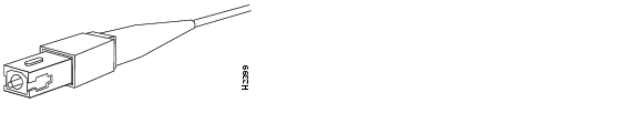
For SONET/SDH multimode and SONET/STC-3 single-mode connections, use one duplex SC connector (see Figure 4-1) or two single SC connectors (see Figure 4-2). The SONET simplex and duplex SC connectors are shipped with removable dust covers on each connector.
Figure 4-1 Duplex SC Connector
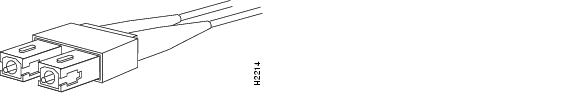
Figure 4-2 Simplex SC Connector
Single-mode and multimode cables should perform to the following specifications:
|
|
|
|
|---|---|---|
ISO/IEC 9314-3 |
2 km (all cables in a connection, end-to-end) |
62.5-micron core with an optical loss of 0 to 9 dB, or 50-micron core with an optical loss of 7 dB |
Note ![]() A single fiber link should not mix 62.5- and 50-micron core cable.
A single fiber link should not mix 62.5- and 50-micron core cable.
SONET Distance Limitations
The SONET specification for fiber-optic transmission defines two types of fiber: single-mode and multimode. Modes can be thought of as bundles of light rays entering the fiber at a particular angle. Single-mode fiber allows only one mode of light to propagate through the fiber, while multimode fiber allows multiple modes of light to propagate through the fiber. Multiple modes of light propagating through the fiber travel different distances depending on the entry angles. The differing travel speeds cause the modes to arrive at the destination at different times. Single-mode fiber is capable of higher bandwidth and greater cable run distances than multimode fiber.
The typical maximum distances for single-mode and multimode transmissions, as defined by SONET, are shown in Table 4-1. If the distance between two connected stations is greater than this maximum distance, significant signal loss can result, making transmission unreliable.
|
|
Budget |
|
|
Between Stations 1 |
|---|---|---|---|---|
Single-mode2 |
13 dB3 |
-28 to -8 dBm |
Up to 9.3 miles (15 km) |
|
Multimode |
11 dB |
-19 to -14 dBm |
-30 to -14 dBm |
Up to 1.2 miles (2 km) |
1 Table 4-1 gives typical results. Use the power budget calculations described below to determine the actual distances. 2 Complies with Bellcore GR-253 Intermediate Reach Specification. 3 dB = decibels 4 dBm = decibels per milliwatt 5 nm = nanometers |
Determining the Power Budget
To design an efficient optical data link, evaluate the power budget. The power budget is the amount of light available to overcome attenuation in the optical link and to exceed the minimum power that the receiver requires to operate within its specifications. Proper operation of an optical data link depends on modulated light reaching the receiver with enough power to be correctly demodulated.
Attenuation, caused by the passive media components (cables, cable splices, and connectors), is common to both multimode and single-mode transmission.
The following variables reduce the power of the signal (light) transmitted to the receiver in multimode transmission:
•![]() Chromatic dispersion (spreading of the signal in time because of the different speeds of light wavelengths)
Chromatic dispersion (spreading of the signal in time because of the different speeds of light wavelengths)
•![]() Modal dispersion (spreading of the signal in time because of the different propagation modes in the fiber)
Modal dispersion (spreading of the signal in time because of the different propagation modes in the fiber)
Attenuation is significantly lower for optical fiber than for other media. For multimode transmission, chromatic and modal dispersion reduce the available power of the system by the combined dispersion penalty (dB). The power lost over the data link is the sum of the component, dispersion, and modal losses.
Table 4-2 lists the factors of attenuation and dispersion for typical fiber-optic cable.
|
|
|
|
|---|---|---|
Attenuation |
0.5 dB |
1.0 dB/km |
Dispersion |
No limit |
500 MHz/km1 |
1 The product of bandwidth and distance must be less than 500 MHz/km. |
Approximating the PA-A1 ATM Power Margin
The LED used for a multimode transmission light source creates multiple propagation paths of light, each with a different path length and time requirement to cross the optical fiber, causing signal dispersion (smear). Higher order mode loss (HOL) results when light from the LED enters the fiber and radiates into the fiber cladding. A worst case estimate of power margin (PM) for multimode transmissions assumes minimum transmitter power (PT), maximum link loss (LL), and minimum receiver sensitivity (PR). The worst case analysis provides a margin of error; not all of the parts of an actual system will operate at the worst case levels.
The power budget (PB) is the maximum possible amount of power transmitted. The following equation lists the calculation of the power budget:
PB = PT - PR
PB = -20 decibels per meter (dBm) - (-30 dBm)
PB = 10 dB
The power margin calculation is derived from the power budget and subtracts the link loss:
PM = PB - LL
If the power margin is positive, the link usually will work.
Table 4-3 lists the factors that contribute to link loss and the estimate of the link loss value attributable to those factors.
After calculating the power budget minus the data link loss, the result should be greater than zero. Circuits whose results are less than zero may have insufficient power to operate the receiver.
The SONET specification requires that the signal must meet the worst case parameters listed in Table 4-4.
|
|
|
|
|---|---|---|
PT |
-15 dBm |
-20 dBm |
PR |
-31 dBm |
-30 dBm |
PB |
13 dB |
11 dB |
Multimode Power Budget Example with Sufficient Power for Transmission
The following is an example of multimode power budget calculated based on the following variables:
•![]() Length of multimode link = 3 kilometers (km)
Length of multimode link = 3 kilometers (km)
•![]() 4 connectors
4 connectors
•![]() 3 splices
3 splices
•![]() Higher order loss (HOL)
Higher order loss (HOL)
•![]() Clock recovery module (CRM)
Clock recovery module (CRM)
Estimate the power budget as follows:
PB = 11 dB - 3 km (1.0 dB/km) - 4 (0.5 dB) - 3 (0.5 dB) - 0.5 dB (HOL) - 1 dB (CRM)
PB = 11 dB - 3 dB - 2 dB - 1.5 dB - 0.5 dB - 1 dB
PB = 3 dB
The positive value of 3 dB indicates that this link would have sufficient power for transmission.
Multimode Power Budget Example of Dispersion Limit
The following example has the same parameters as the previous example, but with a multimode link distance of 4 km:
PB = 11 dB - 4 km (1.0 dB/km) - 4 (0.5 dB) - 3 (0.5 dB) - 0.5 dB (HOL) - 1 dB (CRM)
PB = 11 dB - 4 dB - 2 dB - 1.5 dB - 0.5 dB - 1 dB
PB = 2 dB
The value of 2 dB indicates that this link would have sufficient power for transmission. But, because of the dispersion limit on the link (4 km x 155.52 MHz > 500 MHz/km), this link would not work with multimode fiber. In this case, single-mode fiber would be the better choice.
Single-Mode Transmission
The single-mode signal source is an injection laser diode. Single-mode transmission is useful for longer distances, because there is a single transmission path within the fiber and smear does not occur. In addition, chromatic dispersion is also reduced because laser light is essentially monochromatic.
The maximum overload specification on the single-mode receiver is -14 dBm. The single-mode receiver can be overloaded when using short lengths of fiber because the transmitter can transmit up to -8 dB, but no damage to the receiver will result.

SONET Single-Mode Power Budget Example
The following example of a single-mode power budget assumes two buildings, 8 kilometers apart, are connected through a patch panel in an intervening building with a total of 12 connectors:
•![]() Length of single-mode link = 8 km
Length of single-mode link = 8 km
•![]() 12 connectors
12 connectors
Estimate the power margin as follows:
PM = PB - LL
PM = 13 dB - 8 km (0.5 dB/km) - 12 (0.5 dB)
PM = 13 dB - 4 dB - 6 dB
PM = 3 dB
The value of 3 dB indicates that this link would have sufficient power for transmission and is not in excess of the maximum receiver input power.
Using Statistics to Estimate the Power Budget
Statistical models more accurately determine the power budget than the worst case method. Determining the link loss with statistical methods requires accurate knowledge of variations in the data-link components. Statistical power budget analysis is beyond the scope of this document. For further information, refer to UNI Forum specifications, ITU-T standards, and your equipment specifications.
 Feedback