[an error occurred while processing this directive]

Support

Chapter 4 - Troubleshooting

 Feedback

Table Of Contents

Troubleshooting

Troubleshooting Overview

Initialization and Self-Test Problems

Troubleshooting Subsystems

Coaxial Cable Subsystem

RF and Digital Subsystem

Ethernet Subsystem

USB Subsystem

PC Subsystem

VoIP Subsystem

Further Contacts


Troubleshooting


This chapter provides basic installation troubleshooting information. The chapter includes the following sections:

Troubleshooting Overview

Initialization and Self-Test Problems

Troubleshooting Subsystems

Further Contacts


Note This chapter provides only hardware troubleshooting information that does not require access to the cable voice adapter's command-line interface (CLI) or knowledge of CLI commands.


Troubleshooting Overview

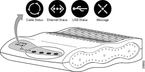
Installation problems with Cisco CVA122/CVA122E Cable Voice Adapter are commonly due to the cable system and its topography. The LEDs on the front panel reveal operational status and help you determine problem areas. See Figure 4-1 for the layout of the LEDs on the Cisco CVA122/CVA122E Cable Voice Adapter's front panel. See Table 1-1 for a description of these LEDs.

Figure 4-1 Cisco CVA122/CVA122E Cable Voice Adapter Front Panel LEDs

Initialization and Self-Test Problems

When the Cisco CVA122/CVA122E Cable Voice Adapter first powers on, the following occurs:

1. The cable voice adapter runs its self-test and diagnostic procedures. All LEDs briefly light and then turn off when self-test and diagnostic procedures are successful. The procedures ensure that all components are functioning. To complete all self-test and diagnostic procedures, the Cisco CVA122/CVA122E Cable Voice Adapter must be able to:

Perform a system reset trap.

Fetch and execute instructions from the ROM Monitor area of the Flash memory chip.

Write several internal registers and reset the control processor successfully.

Correctly configure the port registers.

Perform conditional branches.

Verify that the software-controlled LEDs are functional.

If all diagnostic procedures are successful, the LEDs briefly blink.

2. The next step of the self-test initializes the memory controller and its Dynamic Random Access Memory (DRAM). If this step succeeds,

The cable voice adapter first attempts to initialize the memory controller. If this fails, the USB LED lights and remains on to indicate a problem with the memory controller. Otherwise, the console port is initialized and the banner is output to the console port.

Next, the cable voice adapter performs a self-test on the low registers of the DRAM. If a problem exists, the Cable Status, Ethernet, and USB LEDs light and remain on to indicate a problem with low memory.

The cable voice adapter then attempts to clear the processor's cache memory. If this fails, the Ethernet LED lights and remains on indicate a processor cache failure.

The cable voice adapter then attempts to clear the BSS area of the DRAM; if this fails, the Cable Status and Ethernet LEDs light and remain on to indicate a memory or controller problem. If this test succeeds, the Message LED begins blinking.

Finally, the cable voice adapter attempts to clear the rest of DRAM. If this fails, the Ethernet and USB LEDs remain on to indicate a possible memory or controller problem.

Table 4-1 summarizes the self-test failure codes displayed by the LEDs; these patterns appear when the Cisco CVA122/CVA122E Cable Voice Adapter has failed to complete a self-test and enters its diagnostics mode.

Table 4-1 LED Self-Test Failure Codes

Cable Status
Ethernet
USB
Error Description
   

ON

Initialization of the memory controller failed.

ON

ON

ON

The self-test of the low registers of the DRAM failed. This indicates a problem with low memory.


ON


The self-test of the processor cache memory failed. This indicates a processor cache failure.

ON

ON


A memory or controller problem was detected while clearing the BSS area of the DRAM.


ON

ON

A memory or controller problem was detected while clearing the remaining DRAM.


If the main memory initialization routine successfully completes, all LEDs turn off.

3. If all self-tests passed, the cable voice adapter boots the Cisco IOS image stored in its Flash memory. The Message LED blinks during the boot process and continues blinking until it finishes booting the Cisco IOS image; after loading the image, the Message LED turns off. If the Message LED does not start to blink, or if it continues to blink for more than ten minutes, proceed to the "Troubleshooting Subsystems" section.

4. The cable voice adapter starts normal operations after it starts up the Cisco IOS image. At this point, the LEDs indicate the status of the cable voice adapter:

The Cable Activity LED blinks to indicate activity on the cable interface and remains on otherwise.

The Ethernet LED goes on solid when the Ethernet interface is properly connected to an Ethernet network interface card on a PC. The Ethernet LED also blinks to indicate activity on the Ethernet interface.

The USB LED goes on solid when the USB port is properly connected to a USB port on a PC. The USB LED also blinks to indicate activity on the USB interface.

The service provider controls the Message LED, which can be used to notify the user of special events, such as waiting voicemail or email. Contact your service provider for details on this LED.

5. When the cable voice adapter and computer have booted successfully, you should be able to access an Internet web site, which will confirm that the cable voice adapter is configured correctly. If you cannot access a web site, proceed to the "PC Subsystem" section.

Troubleshooting Subsystems

The key to troubleshooting is to isolate a problem to a specific subsystem:

Coaxial Cable Subsystem

RF and Digital Subsystem

Ethernet Subsystem

USB Subsystem

PC Subsystem

VoIP Subsystem

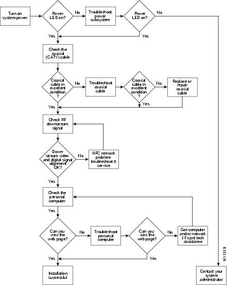
Figure 4-2 on the next page provides a general troubleshooting flowchart. Table 4-2 can help you correlate LED behavior with possible problems, and suggested courses of actions.

Figure 4-2 Basic Troubleshooting Strategy for Startup Problems

Table 4-2 LED Troubleshooting Tips1  

Icon
LED
Status
Possible Problem
Suggested Action

Cable and Power Status

Cable Status LED is blinking.


Cable Status LED remains off.

System is locking on to downstream and upstream channels.

Power cord not connected.

Power outlet not operating.

Power supply has failed.

Wait until the cable voice adapter finishes its power-up sequence. If the blinking is continuous, contact your service provider.

Check power connections.

Check the outlet or try another one.

Replace the power supply.

Ethernet

Ethernet LED remains off.

Ethernet interface is not in use.


PC not powered on.

Bad Ethernet connection.

Incorrect cable between the cable voice adapter, hub (if one is being used), and the PC.


Ethernet driver and TCP/IP software not installed.


Faulty Ethernet card.

This is normal behavior when the Ethernet interface is not used.

Verify the PC is powered on.

Reseat the Ethernet cable at both ends.

Verify that the Ethernet cable is the correct type (straight-through or cross-connect) for the equipment used. If using an Ethernet hub, try connecting a PC directly to the cable voice adapter using a straight-through cable.

Install the proper driver and TCP/IP software for the Ethernet card and verify that DHCP is enabled on the PC.

Replace the Ethernet card.

USB

USB LED is off.

USB interface is not in use.


USB cable is not connected to cable voice adapter and PC.


USB software drivers are not installed on the PC.


PC is running Windows 95 or Windows NT.

This is normal behavior when the USB interface is not used.

Verify that the correct cable (host-device cable with type "A" and type "B" connectors, maximum length 5 meters) is being used and is firmly inserted in both connectors.

Install the USB software according to the instructions in the booklet that accompanies the USB driver CD.

Windows 95 and Windows NT do not contain support for USB networking. Install Windows 98, Windows 2000, or Windows Millennium.

Message

This LED is defined by the service provider. Contact your service provider for details on its use and meaning.

1 If using the CVA120 Series Universal Power Supply (UPS), the UPS contains two LEDs that give additional information about the power supply to the Cisco CVA122/CVA122E Cable Voice Adapter. See the documentation accompanying the UPS for details.


Coaxial Cable Subsystem

For proper operation the Cisco CVA122/CVA122E Cable Voice Adapter must be able to establish a connection with the service provider's CMTS. There are many conditions inherent to coaxial cable that can inhibit this connection:


Step 1 Verify the cable connection from the cable voice adapter to the HFC plant and headend by checking the video reception. You should test the same coaxial cable that the cable voice adapter is connected to—if necessary, disconnect the cable voice adapter from the coaxial cable and connect a cable-ready TV in its place.

If the TV does not receive any cable channels, contact the service provider to re-establish service to the site. If the TV does receive cable channels, it indicates that the basic infrastructure between the site and the HFC plant and headend is working; however, because data connections are much more sensitive to signal interference than cable TV service, it is still possible that a problem exists that prevents reception of the data signals.

Step 2 If you are using a splitter or couple to share the coaxial cable between a TV and the cable voice adapter, remove the splitter/coupler, TV, and any other devices connected to the cable (such as video or DVD players) so that the cable voice adapter connects directly to the coaxial cable coming out of the CATV wall outlet. Make sure the cable voice adapter is the only device on this segment of cable.

If the cable voice adapter functions in this configuration, inspect the splitter and any other devices that were installed on this cable segment. If necessary, upgrade them and their interconnecting cables with ones that have higher-quality connectors—see "Coaxial Connector and Cable Specifications" in "Connector and Cable Specifications" for the recommended cable and connector quality. A high-pass filter might be necessary between the modem and TV to prevent signal interference. If this does not help, you might need to install a separate cable for TV reception.

Step 3 Disconnect the coaxial cable from the back of the cable voice adapter and inspect the cable and its connector. Is the center conductor on the coaxial cable end straight and of the correct length to ensure a good connection?

If the center conductor is not straight or appears to be too long or too short, cut the coaxial cable behind the connector end, and strip the insulation back. Make sure that the newly exposed center conductor is straight. Before replacing the new cable connector end, check the general condition of the cable. Make sure the new conductor end is securely crimped to the cable.


Note The center connector should extend 1/8 inch (3.2 mm) beyond the end of the connector.


Step 4 Is the coaxial cable running to the cable voice adapter in excellent condition?

The coaxial cable between the cable voice adapter and the cable tap must be very high quality. The cable insulation must be at least 80% braid with foil. If the existing cable appears to be of lesser quality or in poor condition, replace the cable from the ground block or tap to the cable end.

Step 5 Is the coaxial cable connection to the back of the cable voice adapter secure?

Check that the coaxial cable end is securely screwed onto the F-connector at the back of the cable voice adapter. Hand-tighten the connector, making sure it is finger tight; then give it a 1/6 turn.


Note If you are unable to resolve the problem, contact your internal service organization for instructions and assistance.


RF and Digital Subsystem

The use of RF and digital signals on the same cable can lead to interference if the HFC network is not correctly configured.


Step 1 Is the downstream video signal being received at the ground block or at the tap?

Connect a premium services cable converter to the ground block or at the tap and contact field service dispatch. Ask the CMTS system administrator to check if they can locate the box on the network by sending an impulse, or on-demand, video signal to the converter.

If field service can locate the converter at the ground block or at the tap, repeat the test with the cable voice adapter connected to the cable end near the computer.

If field service cannot locate the converter at the cable end, but can locate the converter at the ground block or tap, replace the cable from the ground block or tap to the cable end.

Step 2 Check the adjacent video channel. The digital data signal should be approximately in the range of -2 to +15 dBmV on a nearby analog channel. Confirm this value using a portable field strength meter, or power meter, to measure the adjacent analog video signal.


Ethernet Subsystem

Use the following procedure if you cannot communicate with the Internet from a PC that connects to the Cisco CVA122/CVA122E Cable Voice Adapter using an Ethernet connection.


Step 1 Is the Ethernet LED on the front panel of the Cisco CVA122/CVA122E Cable Voice Adapter turned on?

If the Ethernet LED does not light, do the following until the LED begins to light:

a. Verify that the Cisco CVA122/CVA122E Cable Voice Adapter and computer are both powered on.

b. Disconnect the Ethernet cable between the cable voice adapter and computer and reconnect it, making sure it is firmly seated in each connector.

c. Verify that the Ethernet cable is connected to the proper RJ-45 connector on the computer. If the computer has multiple RJ-45 connectors, verify that the one you are using is the connector for the Ethernet card configured for use with the cable voice adapter.

d. Verify that the Ethernet cable is the proper type for the equipment used. A straight-through cable should be used when connecting the cable voice adapter to a computer. A crossover cable should be used when connecting to an Ethernet hub (although if the Ethernet hub has an uplink port, you might be able to use a straight-through cable).

e. If using an Ethernet hub, verify that the correct Ethernet cables are connecting the computers to the hub. (See the hub's documentation for details on the correct cables that should be used.)

f. If using an Ethernet hub, try connecting a computer directly to the cable voice adapter using a straight-through cable.

Step 2 Does the Ethernet LED blink when you attempt to access a site on the Internet?

If the Ethernet LED does not blink, check that the software drivers for the computer's Ethernet card are installed.

a. Choose Start:Settings>Control Panel to display the Control Panel.

b. Double-click the Network icon.

c. Click the Configuration tab.

d. Scroll through the network components list and verify that the list contains both a driver for the Ethernet card and a driver for the TCP/IP software for the Ethernet card.

If either driver does not appear, install the proper drivers for your Ethernet card and its TCP/IP software.

Step 3 Is the computer's TCP/IP software configured for dynamic IP addressing (DHCP)?

a. Display the Network Configuration window, as described above.

b. Click on the component for the TCP/IP software for the Ethernet card.

c. Click the Properties button and verify that the IP address is set for Obtain an IP address automatically.

d. Choose Start>Run and enter winipcfg in the dialog box (Windows 95/98/Millennium) or ipconfig (Windows NT/2000).

e. In the IP configuration dialog box, select the Ethernet adapter from the pull-down menu and click the Renew All button to force the computer to obtain an IP address from the DHCP server at the headend.

Step 4 Did the computer obtain an IP address from the headend?

If the computer could not obtain an IP address from the headend, try removing and reinstalling the Ethernet card, following the directions given in its documentation. In particular, verify that the card does not conflict with any other devices:

a. Choose Start:Settings>Control Panel to display the Control Panel.

b. Double-click the System icon.

c. Click the Devices tab and then click on the plus sign next to Network adapters.

d. Verify that the display for the Ethernet card does not contain either a red "X" or a yellow exclamation point. If it does, then the Ethernet card has a conflict with some other device in the computer. This conflict must be resolved before proceeding; to identify the conflict, select the Ethernet card, click on Properties, and then click on the Resources tab.

e. If the above fails, replace the Ethernet card.

USB Subsystem

Use the following procedure if you cannot communicate with the Internet from a PC that connects to the Cisco CVA122/CVA122E Cable Voice Adapter using a USB connection.


Step 1 Is the computer running Windows 98, Windows Millennium, or Windows 2000?

If not, install Windows 98, Windows Millennium, or Windows 2000 on this computer. Windows 95 and Windows NT do not support networking through the USB interface.

Step 2 Is the USB LED on the front panel of the Cisco CVA122/CVA122E Cable Voice Adapter on?

If the USB LED does not light, do the following until the LED begins to light:

a. Verify that the Cisco CVA122/CVA122E Cable Voice Adapter and computer are both powered on.

b. Verify that the correct cable (host-device cable with type "A" and type "B" connectors, maximum length 5 meters) is being used and is firmly connected to both the cable voice adapter and PC.

c. Disconnect the USB cable between the cable voice adapter and computer and reconnect it, making sure it is firmly seated in each connector.

d. If using a USB hub, try disconnecting all devices and connecting the Cisco CVA122/CVA122E Cable Voice Adapter directly to the computer using a host-to-device (type "A" to type "B")

Step 3 Does the USB LED blink when you attempt to access a site on the Internet?

If the USB LED does not blink, check that the USB software drivers are installed.

a. Choose Start:Settings>Control Panel to display the Control Panel.

b. Double-click the Network icon.

c. Click the Configuration tab.

d. Scroll through the network components list and verify that the list contains both a driver for the Cisco CVA122/CVA122E Cable Voice Adapter and a driver for TCP/IP software for the Cisco CVA122/CVA122E Cable Voice Adapter.

e. If either driver does not appear, install the USB software according to the instructions in the booklet that accompanies the Cisco CVA120 series USB driver software CD.

PC Subsystem

To isolate a problem with a PC that is connected to the Cisco CVA122/CVA122E Cable Voice Adapter:


Step 1 Can you access a web page using the web browser installed on the computer?

If you cannot access a web page, verify that the computer network protocol is configured for TCP/IP and that DHCP services are enabled using the following Windows options:

a. Turn on your PC and enter your network username and password.

b. Choose Start:Settings>Control Panel to display the Control Panel.

c. Double-click the Network icon. The Network window appears with the Configuration tab in the foreground. If the Configuration tab is not in the foreground, click this tab.

d. Scroll the network components list box until the Ethernet adapter TCP/IP option displays for your network adapter or USB port and double-click the selection. The TCP/IP Properties window appears with the IP Address tab in the foreground. If the IP Address tab is not in the foreground, click this tab.


Note If there is no TCP/IP entry for the installed network adapter or USB port, the Windows software is not configured for IP operation. See the computer and network interface card user guides on how to configure these settings.


e. Make sure that the button next to Obtain an IP address automatically is selected. If this button is not selected, the computer is not configured for DHCP. Select the Obtain an IP address automatically radio button now and save the configuration settings.

f. Close all networking windows and close the Control Panel.

g. Follow the onscreen instructions and reboot your PC.

Step 2 Is the network interface (Ethernet or USB) operational?

See the steps given in "Ethernet Subsystem" section and "USB Subsystem" section to troubleshoot the network interface connection on the computer.

Step 3 Is the computer already configured to work with special software such as America Online? Some computers come with dialup adapters preconfigured to work with special software. To ensure the setup is correct, follow the procedures below.

Setting the Internet Properties

a. Turn on your PC and enter your network username and password.

b. Choose Start:Settings:Control Panel to display the Control Panel.

c. Double-click the Internet icon. The Internet Properties window appears with the General tab in the foreground.

d. Click the Connection tab. The Internet Properties Connection tab displays. The Connect to the Internet: as needed check box is checked and the name of the dialup adapter appears in the Dial-Up Networking connection list box.

e. Click the Connect to the Internet: as needed check box to deselect the option.


Note The check box must not be checked. If the checkbox is checked, the computer attempts to open a dialup adapter connection each time a network application is started.


f. Click OK.

g. From the Control Panel, double-click the System icon. The System Properties window displays with the General tab in the foreground.

h. Click the Device Manager tab.

i. Click the Network adapter selection. Make sure the display does not contain either a red "X" or a yellow exclamation point.

j. Click OK.

Setting Network Components

a. Turn on your PC and enter your network user name and password.

b. Choose Start:Settings:Control Panel to display the Control Panel.

c. Double-click the Network icon. The Network window appears with the Configuration tab in the foreground.

d. Scroll the list box until the particular dialup adapter selection appears. If the computer has America Online installed, two network components will be displayed: AOL Dialup Adapter and TCP/IP:AOL Dialup Adapter.


Note The computer might have more than one dialup adapter. Be sure to select the right dialup adapter.


e. If the subscriber does not intend to use America Online, remove both these components from the Network components list box:

Click AOL Dialup Adapter to highlight it. Click Remove.

Click TCP/IP:AOL Dialup Adapter to highlight it. Click Remove.

f. If the subscriber intends to use America Online, double-click the TCP/IP component associated with the dialup adapter. The TCP/IP Properties window appears with the IP Address tab in the foreground.

g. Click the Obtain an IP address automatically button. The IP address for the dialup connection will only be assigned when the connection is made. By default, the computer will be assigned an IP address by the Cisco CVA122/CVA122E Cable Voice Adapter via DHCP.


Note When set up correctly, the Cisco CVA122/CVA122E Cable Voice Adapter is the default Internet connection device. The subscriber might select the dialup adapter as an alternative connection path.


h. Click OK. A dialog box appears, informing you for the change to become effective, the computer must be rebooted.

i. Click Yes to reboot the computer.


VoIP Subsystem

If you do not have dial tone when picking up a telephone or fax device connected to the Cisco CVA122/CVA122E Cable Voice Adapter's voice ports, verify the following:


Step 1 Has the subscriber has purchased voice services from the service provider?

Voice services must be enabled and configured by the service provider before they can be used. Verify that the subscriber's service contract provides voice services.

Step 2 Have voice services been enabled in the configuration file that is downloaded to the Cisco CVA122/CVA122E Cable Voice Adapter at system startup?

If necessary, contact your provisioning or billing administrator or customer service department. If the provisioning or billing system is designed to support automatic feature upgrades, and the cable voice adapter's UID (cable MAC address) is already in the billing system and configured for use with voice, ask to have the cable voice adapter refreshed with the correct voice configuration.

Step 3 Does the Cisco IOS image being used on the Cisco CVA122/CVA122E Cable Voice Adapter support the required number of voice ports?

The version of Cisco IOS image software determines whether the Cisco CVA122/CVA122E Cable Voice Adapter supports 0, 1, or 2 voice ports. Verify that the image being used supports the number of voice ports being used by the subscriber.

Step 4 Are the telephone, modem, and FAX devices plugged into the proper voice port connectors on the rear panel of the cable voice adapter?

Verify that the telephone, modem, and FAX devices are plugged in to the "V1+V2" or "V2" voice port assigned to them by the service provider.

Step 5 Is the proper cable connecting the telephone, modem, or FAX device to the Cisco CVA122/CVA122E Cable Voice Adapter?

If connecting a single-line telephone, the cable can be either a two-wire or four-wire cable; when connecting a two-line telephone, the cable must be a four-wire cable. In all cases, the cable must have an RJ-11 connector on at least one end; the other connector depends on the device being connected. Disconnect the cable at both ends and reconnect it, making sure the cable makes a firm and secure fit at both ends. If this doesn't help, replace the cable with a known good cable.

Step 6 Is the telephone, modem, or FAX device a dual-line telephone?

A dual-line telephone must be plugged into the "V1+V2" voice port. Single-line telephones can be plugged into either voice port.

Step 7 Is the telephone, modem, or FAX device an analog (FXS) device that uses a tone pushbutton dial set?

The Cisco CVA122/CVA122E Cable Voice Adapter supports only analog devices that use tone dialing.

Step 8 Is the sum of the RENs of all devices on any one telephone line less than five?

If you have plugged multiple telephone, modem, or FAX devices into the same telephone line to use as extensions, the sum of their Ringer Equivalence Numbers (REN) cannot exceed five. If this happens, the phones might not ring properly or at all. See the documentation for each phone for its REN value.


Further Contacts

If you experience trouble with the startup that is not resolved with the procedures and tips in this chapter, contact field service dispatch for further assistance and instructions. Also see the documentation available in the Broadband Cable section on CCO and the Documentation CD-ROM.


Note Cisco recommends that a CMTS systems engineer or network administrator be available, or on-call, to assist field service technicians or installers in troubleshooting a Cisco CVA122/CVA122E Cable Voice Adapter.

If you are a network administrator or systems engineer with a Cisco product covered under warranty or a maintenance contract, contact Cisco's Technical Assistance Center (TAC) at 800 553-2447, 408 526-7209, or tac@cisco.com.


[an error occurred while processing this directive]