PDF(369.6 KB) View with Adobe Reader on a variety of devices
Updated:July 27, 2010
Bias-Free Language
The documentation set for this product strives to use bias-free language. For the purposes of this documentation set, bias-free is defined as language that does not imply discrimination based on age, disability, gender, racial identity, ethnic identity, sexual orientation, socioeconomic status, and intersectionality. Exceptions may be present in the documentation due to language that is hardcoded in the user interfaces of the product software, language used based on RFP documentation, or language that is used by a referenced third-party product. Learn more about how Cisco is using Inclusive Language.
Configuring the Cisco uBR-MC88V Cable Interface Line Card
First Published: February 15, 2010
Last Modified: June 3, 2015
The Cisco uBR-MC88V cable interface line card is a DOCSIS 3.0 line card designed specifically for Cisco uBR7246VXR and Cisco uBR7225VXR universal broadband routers. This line card transmits and receives radio frequency (RF) signals between the subscriber and the headend over a hybrid fiber-coaxial (HFC) system.
Finding Feature Information
Your software release may not support all the features documented in this module. For the latest feature information and caveats, see the release notes for your platform and software release. To find information about the features documented in this module, and to see a list of the releases in which each feature is supported, see the “Feature Information for Configuring the Cisco uBR-MC88V Cable Interface Line Card” section.
Use Cisco Feature Navigator to find information about platform support and Cisco IOS, Catalyst OS, and Cisco IOS XE software image support. To access Cisco Feature Navigator, go to http://www.cisco.com/go/cfn. An account on Cisco.com is not required.
Prerequisites for Configuring the Cisco uBR-MC88V Cable Interface Line Card
Table 1 lists the general compatibility prerequisites for the Cisco uBR-MC88V cable interface line card.
Table 1 Software and Hardware Compatibility Matrix for the Cisco uBR-MC88V Line Card
CMTS Platform
Processor Engine
Cisco IOS Release
Cisco uBR7246VXR router
Cisco uBR7225VXR router
Network Processing Engine G2 (NPE-G2)
12.2(33)SCD and later
Note The Cisco uBR-MC88V cable interface line card requires the new uBR7246VXR fan tray as part of its hardware. The part number for the new fan tray is MAS-U7246VXR-FAN2.
Restrictions for Configuring the Cisco uBR-MC88V Cable Interface Line Card
Online insertion and removal (OIR) or hot swapping between two Cisco uBR-MC88V line cards is supported in Cisco IOS Release 12.2(33)SCD. However, OIR between line cards of different types is not supported. That is, if you replace an existing Cisco uBR-MC28U line card with the Cisco uBR-MC88V line card, you must reconfigure the line card.
Note We recommend that you reload the Cisco uBR7246VXR or Cisco uBR7225VXR router when replacing a cable interface line card with a card of a different type.
You cannot install any of the existing line cards along with the Cisco uBR-MC88V line card in Cisco IOS Release 12.2(33)SCD.
You cannot configure a bonded channel using the channels of multiple cable interface line cards. A bonded channel must be configured using the channels of the same line card.
Note Note: We cannot bond across cards and cannot make a cable interface (Mac domain) across cards. Channel bonding can be done only on the same card.
The Cisco uBR-MC88V cable interface line card supports the Advanced Encryption Standard (AES) only when the Baseline Privacy Interface Plus (BPI+) is enabled.
Information About the Cisco uBR-MC88V Cable Interface Line Card
The Cisco uBR-MC88V cable interface line card serves as the RF interface between the cable headend and the DOCSIS-compliant cable modems, EuroDOCSIS-compliant cable modems, or set-top boxes (STBs). The Cisco uBR-MC88V cable interface line card has eight RF upstream (US) and two downstream (DS) physical connectors. Each downstream physical connector includes four downstream channels. The Cisco uBR-MC88V line card supports two cable interfaces (MAC domains), and the downstream and upstream channels are dynamically associated with any of these MAC domains.
Upstream data, from the subscriber, comes through the upstream ports (US0–US7) on the Cisco uBR-MC88V cable interface line card. The line card then processes and configures the data and sends it across the backplane to the WAN or backhaul card (or both), and out to the Internet.
Downstream data, to the subscriber, comes from the Internet through the WAN or backhaul card (or both), and across the backplane to the Cisco uBR-MC88V cable interface line card. The Cisco uBR-MC88V line card processes and configures the data and sends it out through the appropriate radio frequency channel on a downstream port (DS0–DS1) to be combined with the rest of the downstream signals in the headend.
The Cisco uBR-MC88V cable interface line card supports both DOCSIS and EuroDOCSIS cable modem networks. The card supports downstream channels in the 69 to 999 MHz range, and upstream channels in the 5 to 55 MHz range. The Cisco uBR-MC88V cable interface line card supports Annex B and Annex A data rates, channel widths, and modulation schemes, and has DOCSIS MAC management and spectrum management capabilities. This card also supports DOCSIS 3.0, A-TDMA, S-CDMA, downstream bonding, and upstream bonding rates.
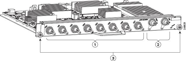
Figure 1 shows the Cisco uBR-MC88V cable interface line card faceplate.
Figure 1 Cisco uBR-MC88V Cable Interface Line Card Faceplate
1
Upstream F-connectors
3
Captive installation screws
2
Downstream F-connectors
—
Table 2 describes the LEDs on the Cisco uBR-MC88V cable interface line card.
Table 2 Cisco uBR-MC88V Cable Interface Line Card LEDs
LED Label
Status
Description
Enabled
Green
Off
The line card is operating normally.
Either the card is shut down or the slot is not working.
US0 through US7
Green
Off
Upstream-enabled path is configured and able to pass traffic.
Upstream port is not enabled.
DS0 through DS1
Green
Off
RF-enabled downstream path is configured and able to pass traffic out through the upconverter at radio frequencies.
RF is not enabled.
Note The LED status of a DS port becomes Off only when all the four RF channels on the port are disabled.
Table 3 shows the supported DOCSIS modulation schemes.
Table 3 Supported DOCSIS and EuroDOCSIS Modulation Schemes
The Cisco uBR-MC88V cable interface line card provides the following benefits:
Additional flexibility for cable operators in partitioning the cable plant to address growing subscriber bandwidth demands; enables cost-effective scalability of services and subscribers.
Hardware-based support for DOCSIS 2.0 (apart from DOCSIS 1.1 features) and DOCSIS 3.0 features such as S-CDMA, Upstream Channel Bonding, and other DOCSIS 3.0 downstream features.
Stacking Number Configuration
A new command, rf-channel stacking, was introduced in Cisco IOS Release 12.2(33)SCD to suppress a carrier or mute an RF channel on the Cisco uBR-MC88V line card. By default, the stacking number is configured as 4. If you change the default stacking number configuration, traffic loss may occur on the active channels. That is, if you change the stacking number from 4 to 2, traffic is interrupted on the RF channels 0 and 1.
However, traffic loss does not occur if you do not change the stacking number configuration when shutting down an RF channe l using the rf-channel rf-shutdown command.
Note We recommend that you do not change the default stacking number configuration. You can change the default configuration when you want RF diagnostics performed on a particular channel. For example, if you want to perform RF diagnostics on RF channel 2, you need to change the default stacking number configuration to 2 to completely mute this channel.
For more information about the rf-channel stacking command, see the Cisco IOS CMTS Cable Command Reference at the following URL:
The Onboard Failure Logging (OBFL) feature enables storage and collection of critical failure information in the NVRAM of the line card. The Cisco uBR-MC88V cable interface line card supports OBFL in Cisco IOS Release 12.2(33)SCD and later.
The OBFL stored data assists in understanding and debugging field failures upon Return Material Authorization (RMA) of a field-replaceable unit at repair and failure analysis sites.
OBFL records operating temperatures, voltages, hardware uptime, and any other important events that assist onboard diagnosis in case of hardware failures.
For more information on the feature, see the Onboard Failure Logging feature guide located at the following URL:
Note The sample output documented in the Onboard Failure Logging feature guide might slightly vary for Cisco CMTS routers.
How to Configure the Cisco uBR-MC88V Cable Interface Line Card
This section describes the steps for configuring the Cisco uBR-MC88V line card at startup. These procedures provide only the initial, basic configuration for the line card.
The universal broadband router must be operational before beginning the following basic configuration procedures for the line card:
Configuring an Integrated Cable Controller Interface on the Cisco uBR-MC88V Line Card
Every downstream port on the Cisco uBR-MC88V line card is configured as an integrated cable controller. Every Cisco uBR-MC88V line card can have up to two integrated cable controllers. You will have to configure all RF channel parameters such as downstream channel ID, frequency, and modulation rates on the controller interface.
Assigns a downstream channel ID to an RF channel in controller configuration mode.
rf-port— RF channel number on the physical port of the line card. The valid range is from 0 to 3.
channel-id—Unique channel ID. The valid range is from 1 to 255.
Note We recommend you to retain the system-generated default channel IDs instead of configuring it.
Step 5
rf-channel rf-port frequency { freq | none } [ annex { A | B } modulation { 64 | 256 } [ interleave-depth value ]]
Router(config-controller)# rf-channel 0 frequency 453000000 annex B modulation 256 interleave-depth 32
Configures the frequency of an RF channel in controller configuration mode.
rf-port—RF channel number on the physical port of the line card. The valid range is from 0 to 3.
freq—Center frequency for the RF channel. The valid range for each RF channel is different based on the Annex type.
none—Removes the specified frequency if the RF channel is shut down.
annex {A | B}—Indicates the MPEG framing format for each RF channel.
– A—Annex A. Indicates that the downstream is compatible with the European MPEG framing format specified in ITU-TJ.83 Annex A.
– B—Annex B. Indicates that the downstream is compatible with the North American MPEG framing format specified in ITU-TJ.83 Annex B.
modulation {64 | 256}—Indicates the modulation rate (64 or 256 QAM) for each RF channel.
interleave-depth value—Indicates the downstream interleave depth. For annex A, the interleave value is 12. For annex B, the valid values are 8, 16, 32, 64, and 128.
Note When the frequency, annex, or modulation is changed, it is reflected across all RF channels in the port. The frequency is automatically assigned using the 6 Mhz or 8 Mhz range based on the annex. The range of the frequency depends on the RF channel being configured.
Sets the RF power output level in the controller integrated cable mode. The RF power for an RF channel is based on the power mode.
rf-port—RF channel number on the physical port of the line card. The valid range is from 0 to 3.
power-level—Desired RF output power level in dBmV. The valid range is from 44 to 63 dBmV. The format is XY.Z. By default,.Z is added as.0. There are four modes of power levels. Mode indicates the number of RF channels enabled on the physical port. The RF channel stacking number configuration determines the power mode on the Cisco uBR-MC88V line card.
– Single Mode: The RF channel stacking number equals to 1 in this mode. The valid range is from 45 to 63 dBmV. (Channel 0 is enabled while the other channels are disabled.)
– Dual Mode: The RF channel stacking number equals to 2 in this mode.The valid range is from 48 to 56 dBmV. (Channels 0 and 1 are enabled; channels 2 and 3 are disabled.)
– Tri Mode: The RF channel stacking number equals to 3 in this mode. The valid range is from 46 to 54 dBmV. (Channels 0, 1, and 2 are enabled; channel 3 is disabled.)
– Quad Mode: The RF channel stacking number equals to 4. The valid range is from 44 to 52 dBmV. (Channels 0, 1, 2, and 3 are enabled.)
Step 7
no rf-channel rf-port rf-shutdown
Router(config-controller)# no rf-channel 0 rf-shutdown
Enables the RF channel.
Step 8
end
Router(config-controller)# end
Exits controller configuration mode and returns to privileged EXEC mode.
Example
The following example shows how to configure an integrated cable controller interface on the Cisco uBR-MC88Vline card:
Router(config-controller)# no rf-channel 3 rf-shutdown
Router(config-controller)# end
Note When you specify the RF channel parameters for the first RF channel on the integrated cable controller, all RF channel parameters except the interleave depth value are autoconfigured for the rest of the RF channels that are shared on the integrated cable controller. For example, if the frequency on RF channel 0 is configured, the frequency on the other RF channels are automatically configured based on the frequency value of RF channel 0.
Configuring a Cable Interface on the Cisco uBR-MC88V Line Card
The cable interface is the MAC domain interface that hosts integrated cable interfaces and associates upstream channels with the integrated cable interfaces.
Configures the RF channels from the Cisco uBR-MC88V cable interface line card to the primary channels in a MAC domain on the same slot and port.
slot —Slot where the line card resides.
– Cisco uBR7246VXR router: The valid range is from 3 to 6.
– Cisco uBR7225VXR router: The valid range is from 1 to 2.
port —Downstream port number on the line card. The allowed port value is 0 or 1.
rf-port—RF channel number. The valid range is from 0 to 3.
upstream grouplist—Specifies the upstream logical identifier. The valid range is dependent on the number of upstream ports configured using the cable upstream max-ports command. If the maximum upstream port number is 8, the valid range for the upstream logical identifier is from 0 to 7. If the maximum upstream port number is 4, the valid range for the upstream logical identifier is from 0 to 3.
Step 5
cable upstream max-ports n
Router(config-if)#
cable upstream max-ports 4
Configures the maximum number of upstreams on a downstream interface on the Cisco uBR-MC88V cable interface line card.
n—Number of upstream ports. The valid range is from 1 to 8. The default value is 4.
Maps an upstream port to a physical port on the Cisco uBR-MC88V cable interface line card for use with a particular downstream.
logical-port—Upstream port number for the logical port assignment. The number of logical ports is configured with the cable modulation-profile command. The valid range is from 0 to 7.
physical-port—Upstream port number for the actual physical port. The valid range is from 0 to 7.
Configures an upstream to use modulation profiles.
n—Upstream port number. The valid range is from 0 to 7.
atdma—Indicates the upstream only for DOCSIS 2.0 Advanced Time Division Multiple Access (A-TDMA) modulation profiles.
scdma—Indicates the upstream only for DOCSIS 2.0 Synchronous Code Division Multiple Access (S-CDMA) modulation profiles.
scdma-d3 —Indicates the upstream only for DOCSIS 3.0 S-CDMA modulation profiles.
tdma—Indicates the upstream only for DOCSIS 1.0 and DOCSIS 1.1 Time Division Multiple Access (TDMA) modulation profiles. The default DOCSIS mode is tdma.
tdma-atdma—Indicates the upstream for both A-TDMA and TDMA operation (mixed mode).
Step 8
cable upstream n channel-width first-choice-width [ last-choice-width ]
Specifies an upstream channel width for an upstream port.
n—Upstream port number. The valid range is from 0 to 7.
first-choice-width—Upstream channel width in hertz (Hz). Valid values for the Cisco uBR-MC88V line card are:
– 1600000 (channel width 1600 kHz, symbol rate 1280 ksym/sec)
– 200000 (channel width 200 kHz, symbol rate 160 ksym/sec)
– 3200000 (channel width 3200 kHz, symbol rate 2560 ksym/sec)
– 400000 (channel width 400 kHz, symbol rate 320 ksym/sec)
– 6400000 (channel width 6400 kHz, symbol rate 5120 ksym/sec)
– 800000 (channel width 800 kHz, symbol rate 640 ksym/sec)
last-choice-width—Upstream channel width in hertz. The valid values are the same as those for the first-choice-width parameter, but for proper operation, the last-choice-width should be equal to or less than the first-choice-width value.
Assigns one or two modulation profiles to an upstream port.
n—Upstream port number. The valid range is from 0 to 7.
primary-profile-number—Primary modulation profile for the upstream port.
secondary-profile-number—Secondary modulation profile for the upstream port. This is used when noise on the upstream increases to the point that the primary modulation profile can no longer be used. Valid values are the same as for the primary modulation profile.
tertiary-profile-number—Tertiary modulation profile for the upstream port.
7. cable rf-bandwidth-percent percent-value [ remaining ratio excess-value ]
8. end
DETAILED STEPS
Command or Action
Purpose
Step 1
enable
Router> enable
Enables privileged EXEC mode.
Enter your password if prompted.
Step 2
configure terminal
Router# configure terminal
Router(config)#
Enters global configuration mode.
Step 3
interface integrated-cable slot/port:rf-channel
Router(config)# interface integrated-cable 5/1:0
Enters the interface configuration mode.
slot —Slot where the line card resides.
– Cisco uBR7246VXR router: The valid range is from 3 to 6.
– Cisco uBR7225VXR router: The valid range is from 1 to 2.
port —Downstream port number on the line card. The valid port value is 0 or 1.
rf-channel—RF channel number. The valid range is from 0 to 3.
Step 4
shutdown
Router(config-if)# shutdown
Shuts down the integrated cable interface.
Note You must shut down a particular interface before enabling dynamic bandwidth sharing (DBS) on that interface.
Step 5
cable dynamic-bw-sharing
Router(config-if)# cable dynamic-bw-sharing
Enables dynamic bandwidth sharing on the integrated cable interface.
Step 6
no shutdown
Router(config-if)# no shutdown
Enables the integrated cable interface.
Step 7
cable rf-bandwidth-percent percent-value [ remaining ratio excess-value ]
Router(config-if)#
cable rf-bandwidth-percent 96
Enables either static or dynamic bandwidth percentage sharing for an integrated cable interface in interface configuration mode.
percent-value —Static bandwidth allocation of a downstream RF channel. The valid range is from 1 to 100.
remaining ratio excess-value —(Optional) Specifies the ratio of the remaining or excess bandwidth that can be allocated to the integrated cable interface. The valid range is from 1 to 100. The default value is 1.
Note This option is available only when dynamic bandwidth sharing is enabled on the Cisco uBR-MC88V cable interface line card.
Step 8
end
Router(config-if)# end
Exits interface configuration mode and returns to privileged EXEC mode.
Example
The following example shows how to configure an integrated cable interface.
Router> enable
Router# configure terminal
Router(config)# interface integrated-cable 5/1:0
Router(config-if)# shutdown
Router(config-if)# cable dynamic-bw-sharing
Router(config-if)# no shutdown
Router(config-if)# cable rf-bandwidth-percent 96
Router(config-if)# end
Configuring a Wideband Cable Interface on the Cisco uBR-MC88V Line Card
A wideband cable interface is a logical representation of the channels in the bonding group and is configured using the interface wideband-cable command.
Restrictions
The maximum number of wideband cable interfaces that can be configured on the Cisco uBR-MC88V line card is 12. A single controller can have up to six wideband cable interfaces on the Cisco uBR-MC88V line card.
SUMMARY STEPS
1. enable
2. configure terminal
3. interface wideband-cable slot / port : wb_channel
Configures the RF channel bandwidth that is allocated to a specified wideband channel or bonding group.
rf-port—RF channel physical port on the field-programmable gate array (FPGA).
bandwidth-percent bw-percent—(Optional) Indicates the bandwidth percentage from this RF channel that is used for the wideband interface. The valid range is from 0 to 100. If the bandwidth percentage is not used, the default bandwidth value is 100 percent.
remaining ratio excess-value—(Optional) Indicates the ratio of the excess bandwidth that is allocated to the wideband interface. The valid range is from 1 to 100. The default value is 1.
Note This option is available only when dynamic bandwidth sharing is enabled on the Cisco uBR-MC88V cable interface line card.
Step 9
cable rf-channel controller port channel rf-port bandwidth-percent bw-percent
Configures the RF channel bandwidth percentage on another controller on the same line card.
controller port—Specifies the controller port value. Valid values are 0 and 1.
channel rf-port—Specifies the RF port.
bandwidth-percent bw-percent—(Optional) Indicates the bandwidth percentage from this RF channel that is used for the wideband interface. The valid range is from 0 to 100 percent. If the bandwidth percentage is not used, the default bandwidth value is 100 percent.
Step 10
cable bonding-group-id bonding-group-id
Router(config-if)# cable bonding-group-id 40
Configures the bonding group ID.
bonding-group-id— Bonding group ID. The valid range is from 1 to 144.
Step 11
end
Router(config-if)# end
Exits interface configuration mode and returns to privileged EXEC mode.
Example
The following example shows how to configure a wideband cable interface on the Cisco uBR-MC88V cable interface line card:
Configures upstream cable connector for a fiber node.
slot —Slot where the line card resides.
– Cisco uBR7246VXR router: The valid range is from 3 to 6.
– Cisco uBR7225VXR router: The valid range is from 1 to 2.
port-number—A range of physical upstream port numbers on the cable interface line card. This can be one or more port numbers or a range of port numbers separated by a hyphen or combinations of both. The valid range for upstream port numbers is from 0 to 7.
Step 6
end
Router(config-fiber-node)# end
Exits fiber-node configuration mode and returns to privileged EXEC mode.
Example
The following example shows how to configure the fiber node on the Cisco uBR-MC88V cable interface line card on the Cisco uBR-MC88V cable interface line card.
Configuration Example for the Cisco uBR-MC88V Line Card
The following is an example of basic configuration details of the Cisco uBR-MC88V line card on a Cisco uBR 7246VXR router:
controller Integrated-Cable 5/0
rf-channel 0 cable downstream channel-id 17
rf-channel 0 frequency 453000000 annex B modulation 256qam interleave 32
rf-channel 0 rf-power 52.0
no rf-channel 0 rf-shutdown
rf-channel 1 cable downstream channel-id 18
rf-channel 1 frequency 459000000 annex B modulation 256qam interleave 32
rf-channel 1 rf-power 52.0
no rf-channel 1 rf-shutdown
rf-channel 2 cable downstream channel-id 19
rf-channel 2 frequency 465000000 annex B modulation 256qam interleave 32
rf-channel 2 rf-power 52.0
no rf-channel 2 rf-shutdown
rf-channel 3 cable downstream channel-id 20
rf-channel 3 frequency 471000000 annex B modulation 256qam interleave 32
rf-channel 3 rf-power 52.0
no rf-channel 3 rf-shutdown
controller Integrated-Cable 5/1
rf-channel 0 cable downstream channel-id 21
rf-channel 0 frequency 477000000 annex B modulation 256qam interleave 32
rf-channel 0 rf-power 52.0
no rf-channel 0 rf-shutdown
rf-channel 1 cable downstream channel-id 22
rf-channel 1 frequency 483000000 annex B modulation 256qam interleave 32
rf-channel 1 rf-power 52.0
no rf-channel 1 rf-shutdown
rf-channel 2 cable downstream channel-id 23
rf-channel 2 frequency 489000000 annex B modulation 256qam interleave 32
rf-channel 2 rf-power 52.0
no rf-channel 2 rf-shutdown
rf-channel 3 cable downstream channel-id 24
rf-channel 3 frequency 495000000 annex B modulation 256qam interleave 32
rf-channel 3 rf-power 52.0
no rf-channel 3 rf-shutdown
interface Cable5/0
downstream Integrated-Cable 5/0 rf-channel 0-3
cable mtc-mode
cable rcp-control verbose
cable enable-trap cmonoff-notification
cable enable-trap cmonoff-interval 500
no cable packet-cache
cable bundle 1
cable upstream max-ports 4
cable upstream bonding-group 1
upstream 1
upstream 2
upstream 3
attributes 80000000
cable upstream 0 connector 0
cable upstream 0 frequency 9000000
cable upstream 0 channel-width 3200000 3200000
cable upstream 0 docsis-mode atdma
cable upstream 0 minislot-size 2
cable upstream 0 range-backoff 3 6
cable upstream 0 modulation-profile 221
no cable upstream 0 shutdown
cable upstream 1 connector 1
cable upstream 1 frequency 13000000
cable upstream 1 channel-width 3200000 3200000
cable upstream 1 docsis-mode atdma
cable upstream 1 minislot-size 2
cable upstream 1 range-backoff 3 6
cable upstream 1 modulation-profile 221
no cable upstream 1 shutdown
cable upstream 2 connector 2
cable upstream 2 frequency 17000000
cable upstream 2 channel-width 3200000 3200000
cable upstream 2 docsis-mode atdma
cable upstream 2 minislot-size 2
cable upstream 2 range-backoff 3 6
cable upstream 2 modulation-profile 221
no cable upstream 2 shutdown
cable upstream 3 connector 3
cable upstream 3 frequency 21000000
cable upstream 3 channel-width 3200000 3200000
cable upstream 3 docsis-mode atdma
cable upstream 3 minislot-size 2
cable upstream 3 range-backoff 3 6
cable upstream 3 modulation-profile 221
no cable upstream 3 shutdown
interface Integrated-Cable5/0:0
cable bundle 1
cable dynamic-bw-sharing
cable rf-bandwidth-percent 30
interface Wideband-Cable5/0:0
cable bundle 1
cable bonding-group-id 13
cable dynamic-bw-sharing
cable rf-channel 0 bandwidth-percent 40
cable rf-channel 1 bandwidth-percent 40
cable rf-channel 2 bandwidth-percent 40
cable fiber-node 1
description FN1-slot5
downstream Integrated-Cable 5/0 rf-channel 0-3
upstream Cable 5 connector 0-3
Verifying and Troubleshooting the Cisco uBR-MC88V Line Card Configuration
This section describes the show commands that you can use to verify the Cisco uBR-MC88V cable interface line card configuration.
To verify the integrated cable controller configuration details, use the show controller integrated-cable command as shown in the following example:
Router# show controller integrated-cable 4/1 config
Integrated Cable Controller 4/1:
----------------------------------
Channel 5 Annex = B Modulation = 64 QAM
Channel 6 Annex = B Modulation = 64 QAM
Channel 7 Annex = B Modulation = 64 QAM
Channel 8 Annex = B Modulation = 64 QAM
Jib3-DS Device Information:
---------------------------
HW Rev ID: 0x00000001 SW Rev ID: 0x0001000B
Device Type: Kawad
Driver State: 3
Channel Resources:
------------------
Total Non-bonded Channels..........= 8
Per-Controller Non-bonded Channels = 4
Total Bonded Channels..............= 12
Per-Controller Bonded Channels.....= 6
Slot-Wide Resources:
--------------------
Number of PHS Rules...........= 12288 (0x3000)
Number of BPI Table Entries...= 24576 (0x6000)
Number of Service Flows.......= 65536 (0x10000)
Sniffer Configuration:
----------------------
Non-Bonded Channel Mask = 0x00000000
Bonded Channel Mask.....= 0x00000000
Sniff All Enable........= False
Configured Sniffer MAC Addresses:
Entry MAC Address Enabled
----- --------------- -------
0 0000.0000.0000 False
1 0000.0000.0000 False
2 0000.0000.0000 False
3 0000.0000.0000 False
4 0000.0000.0000 False
5 0000.0000.0000 False
6 0000.0000.0000 False
7 0000.0000.0000 False
8 0000.0000.0000 False
9 0000.0000.0000 False
10 0000.0000.0000 False
11 0000.0000.0000 False
12 0000.0000.0000 False
13 0000.0000.0000 False
14 0000.0000.0000 False
15 0000.0000.0000 False
Replication Table:
------------------
Replication Entry Index Channel Mask
----------------------- ------------
Configured Bonding Groups:
--------------------------
Bonded Channel Channels in Bonding Group
-------------- -------------------------
Sync Configuration:
-------------------
Channel MAC Address Interval
------- -------------- --------
DS PHY Configuration of Controller 1:
---------------------
Base Frequency = 477000000Hz
RF-Power = 52.0dBmV
Annex, modulation = Annex B, 64 QAM
Channel Status Interleave
------- ------ ----------
0 Muted 5
1 Muted 5
2 Muted 5
3 Muted 5
To verify information about the interface controllers, use the show controller cable command as shown in the following example:
Router# show controller cable 5/1
Cable5/1 (idb 0x9E4809C)
Hardware is MC88V (F-connector) with Integrated Up-converter
CLC CPU is MPC8548E REV 2.1
Line card information:
System information:
Interface Cable5/1
Hardware is MC88V
Board hardware version :P1
===============CPLD registers===============
Revision regsiter: 0x00020005
IC Reset: 0x000003FF
IC Information: 0x00000013
Reset Cause: 0x00000000
Watchdog Reset: 0x00000000
Watchdog Control: 0x00000001
LED Register: 0x0000000F
Software NMI: 0x00000000
National Clk Sel Status: 0x00000000
CPU to MP Interrupt: 0x00000000
CPU to MP Interrupt en: 0x00000000
JIB Upstream port 0 Enabled Bound to local = 0
To verify information about the upstream related statistics, use the show controller cable command along with the upstream keyword as shown in the following example:
Router# show controller cable 5/1 upstream 0
Cable5/1 Upstream 0 is up
Frequency 10.000 MHz, Channel Width 1.600 MHz, Symbol Rate 1.280 Msps
Modulations - Short QPSK, Long QPSK
This upstream is mapped to physical port 4
Spectrum Group is overridden
US phy MER(SNR)_estimate for good packets - 27.4111 dB
Nominal Input Power Level 0 dBmV, Tx Timing Offset 6768
Ranging Backoff Start 3, Ranging Backoff End 6
US timing offset adjustment type 0, value 0
Ranging Insertion Interval automatic (60 ms)
US throttling off
Tx Backoff Start 3, Tx Backoff End 5
Modulation Profile Group 21
Concatenation is enabled
Fragmentation is enabled
part_id=0x3140, rev_id=0x03, rev2_id=0x00
nb_agc_thr=0x0000, nb_agc_nom=0x0000
Range Load Reg Size=0x58
Request Load Reg Size=0x0E
Minislot Size in number of Timebase Ticks is = 4
Minislot Size in Symbols = 32
Bandwidth Requests = 0x75A
Piggyback Requests = 0x2C8
Invalid BW Requests= 0x0
Minislots Requested= 0xE62F
Minislots Granted = 0xA23
Minislot Size in Bytes = 8
Map Advance (Dynamic) : 2940 usecs
Map Count = 4957413
Remote Map Counts: LC 5 = 4954741
UCD Count = 0
Remote UCD Counts:
LC 5/1:0 = 5264
PHY: us errors 0 us recoveries 2
MAC PHY TSS: tss error start 0 tss error end 0
MAC PHY Status: bcm3140 status 0 lookout status 0
Not Bound to Local Downstream
MAP/UCD Replication Instructions:
LC 5 index = 37, bitmap = 0x0010
To verify the channel grouping domain (CGD) associations of a cable MAC domain, use the show cable mac-domain cgd-associations command as shown in the following example:
Router# show cable mac-domain cable cgd-associations
To know about the DOCSIS 3.0 features supported with the Cisco uBR-MC88V line card, see the New Features in Cisco IOS Release 12.2(33)SCD document at the following URL:
No new or modified RFCs are supported, and support for existing RFCs has not been modified.
—
Technical Assistance
Description
Link
The Cisco Support website provides extensive online resources, including documentation and tools for troubleshooting and resolving technical issues with Cisco products and technologies.
To receive security and technical information about your products, you can subscribe to various services, such as the Product Alert Tool (accessed from Field Notices), the Cisco Technical Services Newsletter, and Really Simple Syndication (RSS) Feeds.
Access to most tools on the Cisco Support website requires a Cisco.com user ID and password.
Feature Information for Configuring the Cisco uBR-MC88V Cable Interface Line Card
Table 4 lists the release history for this feature.
Not all commands may be available in your Cisco IOS software release. For release information about a specific command, see the command reference documentation.
Use Cisco Feature Navigator to find information about platform support and software image support. Cisco Feature Navigator enables you to determine which Cisco IOS and Catalyst OS software images support a specific software release, feature set, or platform. To access Cisco Feature Navigator, go to http://www.cisco.com/go/cfn. An account on Cisco.com is not required.
NoteTable 4 lists only the Cisco IOS software release that introduced support for a given feature in a given Cisco IOS software release train. Unless noted otherwise, subsequent releases of that Cisco IOS software release train also support that feature.
Table 4 Feature Information for the Cisco uBR-MC88V Cable Interface Line Card
Feature Name
Releases
Feature Information
Configuring the Cisco uBR-MC88V Cable Interface Line Card
12.2(33)SCD
The Cisco uBR-MC88V line card was introduced on the Cisco uBR7246VXR and Cisco uBR7225VXR universal broadband routers.
The following sections provide information about this feature:
The following commands were introduced or modified:
rf-channel stacking
controller integrated-cable
downstream integrated-cable
interface integrated-cable
interface wideband-cable
Cisco and the Cisco logo are trademarks or registered trademarks of Cisco and/or its affiliates in the U.S. and other countries. To view a list of Cisco trademarks, go to this URL: www.cisco.com/go/trademarks. Third-party trademarks mentioned are the property of their respective owners. The use of the word partner does not imply a partnership relationship between Cisco and any other company. (1110R)
Any Internet Protocol (IP) addresses and phone numbers used in this document are not intended to be actual addresses and phone numbers. Any examples, command display output, network topology diagrams, and other figures included in the document are shown for illustrative purposes only. Any use of actual IP addresses or phone numbers in illustrative content is unintentional and coincidental.

 Feedback