Table of Contents
Configuring the Cisco uBR-MC3GX60V Cable Interface Line Card
Finding Feature Information
Contents
Prerequisites for Configuring the Cisco uBR-MC3GX60V Cable Interface Line Card
Restrictions for Configuring the Cisco uBR-MC3GX60V Cable Interface Line Card
Information About the Cisco uBR-MC3GX60V Cable Interface Line Card
Downstream Sharing Between the Cisco uBR-MC3GX60V Line Card and Cisco Wideband SPA
Onboard Failure Logging
Bonding Across 3G60 Controllers Support
Adjacency Resolution
How to Configure the Cisco uBR-MC3GX60V Cable Interface Line Card
Configuring the Modular Cable Controller on the Cisco uBR-MC3GX60V Cable Interface Line Card
Examples
Troubleshooting Tips
Configuring the GigE Interface for Downstream on the CiscouBR-MC3GX60V Cable Interface Line Card
Configuring a Cable Interface on the Cisco uBR-MC3GX60V Cable Interface Line Card
Examples
Troubleshooting Tips
Configuring the Modular Cable Interface on the Cisco uBR-MC3GX60V Cable Interface Line Card
Examples
Troubleshooting Tips
Configuring the Wideband Cable Interface on the Cisco uBR-MC3GX60V Cable Interface Line Card
Restrictions
Examples
Troubleshooting Tips
Configuring Bonding Across 3G60 Controllers Support
Restrictions
Examples
Troubleshooting Tips
Configuring the RF Plant Topology on the Cisco uBR-MC3GX60V Cable Interface LineCard
Prerequisites
Restrictions
Examples
Troubleshooting Tips
Configuring Redundancy on the Cisco uBR-MC3GX60V Cable Interface Line Card
Configuring the GigE Interface for Downstream on the CiscouBR-MC3GX60V Cable Interface Line Card
Prerequisites
Restrictions
Examples
Troubleshooting Tips
Configuring Global HCCP N+1 Line Card Redundancy on the Cisco uBR10012 Router
Prerequisites
Restrictions
Examples
Configuring the DEPI Control Plane on the Cisco uBR-MC3GX60V Cable Interface Line Card
Prerequisites
Restrictions
Examples
Troubleshooting Tips
Configuring Manual DEPI on the Cisco uBR-MC3GX60V Cable Interface Line Card
Prerequisites
Restrictions
Example
Troubleshooting Tips
Monitoring and Maintaining the Cisco uBR-MC3GX60V Cable Interface Line Card
Viewing the Cisco uBR-MC3GX60V Cable Interface Line Card Statistics
Viewing Information About the Cisco uBR-MC3GX60V Line Card and CiscoWideband SPA Downstream Sharing
Examples
Viewing Information About the Interface Controllers
Examples
Viewing Information About the Cable Modems
Examples
Troubleshooting the Cisco uBR-MC3GX60V Cable Interface Line Card
Upgrading Cisco uBR10-MC5X20S/U/H or Cisco UBR-MC20X20V Line Cards to Cisco uBR-MC3GX60V Cable Interface Line Card
Configuration Examples for the Cisco uBR-MC3GX60V Cable Interface Line Card
Configuration Examples for the Cisco uBR-MC3GX60V Cable Interface Line Card along with Wideband SPA
Configuration Restrictions
Configuration Restrictions for Cisco uBR-MC3GX60V Line Card and Cisco Wideband SPA Downstream Sharing
Additional References
Related Documents
Standards
MIBs
Technical Assistance
Feature Information for the Cisco uBR-MC3GX60V Cable Interface Line Card
Configuring the Cisco uBR-MC3GX60V Cable Interface Line Card
First Published: November 29, 2010
Last Updated: May 27, 2013
The Cisco uBR-MC3GX60V cable interface line card is a Cisco modular cable modem termination system (M-CMTS) DOCSIS 3.0-compliant line card designed for the Cisco uBR10012 universal broadband router. It supports 60 upstream and 72 downstream channels.
The Cisco uBR-MC3GX60V cable interface line card offers increased configuration flexibility and provides up to 14 times the downstream data density when compared to earlier generations of cable line cards.
Finding Feature Information
Your software release may not support all the features documented in this module. For the latest feature information and caveats, see the release notes for your platform and software release. To find information about the features documented in this module, and to see a list of the releases in which each feature is supported, see the “Feature Information for the Cisco uBR-MC3GX60V Cable Interface Line Card” section.
Use Cisco Feature Navigator to find information about platform support and Cisco software image support. To access Cisco Feature Navigator, go to
http://www.cisco.com/go/cfn
.
An account on Cisco.com is not required.
Prerequisites for Configuring the Cisco uBR-MC3GX60V Cable Interface Line Card
The Cisco uBR10012 universal broadband router must have two DOCSIS Timing, Communication and Control (DTCC) cards configured in the DOCSIS Timing Interface (DTI) mode to make the Cisco uBR-MC3GX60V cable interface line card work with an Edge QAM (EQAM) device.
Table 1
lists the general compatibility prerequisites for the Cisco uBR-MC3GX60V cable interface line card.
Table 1 Software and Hardware Compatibility Matrix for the Cisco uBR-MC3GX60V Line Card
|
|
|
|
Cisco uBR10012 router
|
PRE4
|
12.2(33)SCE and later releases
|
Cisco uBR10012 router
|
PRE5
|
12.2(33)SCH and later releases
|
Restrictions for Configuring the Cisco uBR-MC3GX60V Cable Interface Line Card
-
The Downstream External PHY Interface (DEPI) control plane and Manual DEPI features cannot be configured on the same Cisco uBR-MC3GX60V line card.
-
High Availability for Cisco Wideband SPA with Cisco uBR-MC3GX60V line card is not supported.
-
If Cisco uBR10-MC5X20 line card is used as working line card and Cisco uBR-MC3GX60V line card used as protect line card, the HCCP feature is not supported when the working line card is replaced (using Online Insertion and Removal (OIR)) with a Cisco uBR-MC3GX60V line card.
-
Port Channel configuration is not supported on Gigabit Ethernet interface of Cisco uBR-MC3GX60 line card.
Information About the Cisco uBR-MC3GX60V Cable Interface Line Card
With 72 downstream and 60 upstream channels, the Cisco uBR-MC3GX60V line card supports 9 service groups (SGs) for 8-channel downstream bonding, and 18 SGs for 4-channel downstream bonding. This line card can provide up to 72 SGs of 8 downstreams for a Cisco uBR10012 router. A larger number of SGs may be supported when downstream channels are shared between MAC domains.
The Cisco uBR-MC3GX60V cable line card has 4 connector inputs and 12 PHY receivers. The upstream channel-to-physical connector assignment is flexible enough to provide any combination of 1 to 12 channels per connector from the 4-connector bundle. This means four separate connectors could provide three US channels each, or two of the four connectors could provide six US channels each, and so on.
Note The Cisco uBR-MC3GX60V line card supports the same number of cable modems and other devices as those supported on other M-CMTS and I-CMTS line cards, on Cisco uBR10012 routers.
The Cisco uBR10012 chassis with the Cisco uBR-MC3GX60V line card offers high density downstream solutions for IP Video over DOCSIS (VDOC) and cable high speed data (HSD) applications.
The Cisco uBR10012 router can include:
-
Up to eight Cisco uBR-MC3GX60V line cards and up to six Cisco Wideband SPAs, or both
-
A mix of older line cards and up to six Cisco Wideband SPAs, or both
-
Cisco uBR-MC3GX60V line card must use PRE4 with SIP-600
-
Dual DTCCs are required even when connected to a single DTI server
The Cisco uBR-MC3GX60V line card offers high availability through:
-
N+1 redundancy for the Cisco uBR-MC3GX60V line card. A Cisco uBR-MC3GX60V can serve as a protect line card for up to seven Cisco uBR-MC3GX60V line cards.
Note Starting with Cisco IOS Release 12.2(33)SCE1, N+1 redundancy feature including DEPI redundancy is supported on the Cisco uBR-MC3GX60V cable interface line card.
-
External RF switch for upstream connectivity.
-
DEPI Path Redundancy (DPR) for M-CMTS interfaces:
– A protocol solution that allows for redundant DEPI connections in N+1 redundancy.
– Minimal packet loss during failovers.
-
PRE redundancy.
-
Six Gigabit Ethernet (GigE) small form-factor pluggable (SFP) ports, organized in three pairs for 1+1 network connectivity redundancy.
Note The GigE ports on the Cisco uBR-MC3GX60V line card support only Layer 2 CIN routing protocols.
Effective with Cisco IOS Release 12.2(33)SCG, you can configure the MAC domain to include the SPA cards and the Cisco uBR-MC3GX60V line card.
In a scenario, where 6 SPA cards and a single Cisco uBR-MC3GX60V line card are present in a chassis, 6 SPA rf-channels and 3 controller rf-channel can be configured as primary channels in a single MAC domain. However, we recommend that
not
more than 3 primary rf-channel controllers are configured in one MAC domain on the Cisco uBR-MC3GX60V line card.
Effective with Cisco IOS Release 12.2(33)SCG1, the Cisco uBR-MC3GX60V line card and up to five shared port adapters (SPAs) can be configured to the same LBG. You can:
-
Include all the downstreams and upstreams of the SPA cards and the Cisco uBR-MC3GX60V line card in the LBG.
-
Configure the fiber-node to include all the downstreams and upstreams of the SPA cards and the Cisco uBR-MC3GX60V line card.
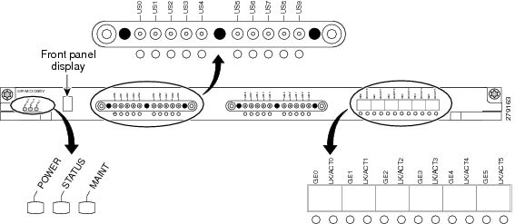
Figure 1 shows the Cisco uBR-MC3GX60V cable interface line card faceplate.
Figure 1 Cisco uBR-MC3GX60V Cable Interface Line Card Faceplate
Downstream Sharing Between the Cisco uBR-MC3GX60V Line Card and Cisco Wideband SPA
Starting with Cisco IOS Release 12.2(33)SCG, MAC domains hosted on the Cisco uBR-MC3GX60V cable interface line card can include downstream channels from the Cisco Wideband SPAs. Each Cisco uBR-MC3GX60V line card, together with the Cisco Wideband SPA, can now support up to 96 downstream channels. With this increased downstream capacity, Cisco uBR10012 router supports more number of CMs.
The Cisco uBR-MC3GX60V line card and the Cisco Wideband SPA downstream sharing is supported on the Cisco CMTS through:
-
The Cisco Wideband SPA downstreams that are included on the same fiber node as the Cisco uBR-MC3GX60V downstreams and upstreams.
-
Any upstream channel of the Cisco uBR-MC3GX60V line card that is bonded with any wideband SPA downstream channel.
-
A maximum of eight Cisco uBR-MC3GX60V line cards and six Cisco Wideband SPAs that are supported on a single chassis.
-
The Cisco uBR-MC3GX60V line card that serves as the modular host for the Cisco Wideband SPA.
-
The Hot-Standby Connection-to-Connection Protocol (HCCP) N+1 Redundancy that is supported for Cisco uBR-MC3GX60V line card with the Cisco Wideband SPA.
For more information on how to configure the Cisco uBR-MC3GX60V line card with the Cisco Wideband SPA, see “Configuring a Cable Interface on the Cisco uBR-MC3GX60V Cable Interface Line Card” section.
For more information on configuring the Cisco Wideband SPA, see the
Cisco uBR10012 Universal Broadband Router SIP and SPA Software Configuration
guide.
Onboard Failure Logging
The On-Board Failure Logging (OBFL) feature enables storage and collection of critical failure information in the non-volatile memory of a Field Replaceable Unit (FRU), like a route processor (RP) or line card. The Cisco uBR-MC3GX60V cable interface line card has 2 MB of non-volatile storage dedicated for OBFL use.
The OBFL stored data assists in understanding and debugging field failures on Return Material Authorization (RMA) of a RP or line card at repair and failure analysis sites.
OBFL records operating temperatures, voltages, hardware uptime, and any other important events that assist onboard diagnosis in case of hardware failures.
For more information about the feature, see the
Onboard Failure Logging
feature guide located at the following URL:
http://www.cisco.com/en/US/docs/ios/12_2sx/12_2sxh/feature/guide/sxhobfl.html#wp1053048.
Note The sample output documented in the Onboard Failure Logging feature guide might slightly vary for Cisco CMTS routers.
Bonding Across 3G60 Controllers Support
Downstream bonding group for a wideband cable interface on Cisco uBR-MC3GX60V includes only DS RF channels from one controller. This restricts the configuration of RF channels to bonding groups on other two controllers of the Cisco uBR-MC3GX60V cable interface line card.
Effective with Cisco IOS Release 12.2(33)SCH, the Bonding Across 3G60 Controllers Support feature allows the downstream bonding groups on one controller to include RF channels across all three downstream controllers. An RF channel can now belong to a maximum number of 96 bonding groups. The maximum number of RF channel members in a bonding group is 24.
For more information on how to configure the Bonding Across 3G60 Controllers Support feature, see Configuring Bonding Across 3G60 Controllers Support.
Adjacency Resolution
When Cisco uBR-MC5X20 line cards are replaced with Cisco uBR-MC3GX60V cable interface line card, the adjacency resolution (ADJ Resolve) process increases the CPU utilization.
The ADJ Resolve process uses ARP for resolution. If the ARP process is successful for an adjacency, then the adjacency is populated. However, if the ARP process is not successful, then the incomplete ARP request is added to the list of incomplete ARP requests and the number (of incomplete ARP requests) is incremented.
Every time an incomplete ARP request is re-sent and returned incomplete, the number is further incremented. As the number of incomplete ARP requests increases, the CPU utilization increases.
To resolve this high utilization of CPU:
-
Increase the number of interface bundles
-
Reduce the number of members per interface bundle
-
Implement ACL or any other mechanism to block scanning
-
Enable Divert Rate Limit (DRL) for fib_rp_glean diverts
DRL
:
To configure token bucket for each source IP address of each WAN, use the
service divert-rate-limit ip divert-code rate
rate
limit
limit
. This sends one packet to the Route Processor for ARP resolution per second with a burst size of 4 packets per second as minimum rate, instead of the default of 4,000 packets per second. This will reduce the ARP packet traffic to the CPU.
The DRL process is optimized with the following parameters:
-
DRL rate - 1 (indicating 1 packet per second being the minimum permitted rate)
-
DRL limit - 4 (indicating burst size of 4 packets per second being the minimum permitted burst size)
DHCP
:
DHCP leasequery eliminates the broadcast of ARP requests to all bundle members and, thus, reduces CPU utilization for ADJ Resolve process.
Use the
cable source-verify dhcp
and
no cable arp
commands to send leasequeries to the DHCP server for unknown IP addresses within the bundle instead of ARP requests.
DHCP leasequery process is optimized with the following parameters:
-
DHCP Leasequery filter packet burst size - 3 packets per second
-
DHCP Leasequery filter interval - 60 seconds interval
How to Configure the Cisco uBR-MC3GX60V Cable Interface Line Card
This section describes the steps for configuring the Cisco uBR-MC3GX60V line card at startup. These procedures provide only the initial, basic configuration for the line card.
The Cisco uBR10012 universal broadband router should be operational before beginning the following procedures to configure the Cisco uBR-MC3GX60V cable interface line card:
Note For Annex A and 256 QAM, each Cisco uBR-MC3GX60V supports up to 54 RF channels (18 channels on every controller) at full rate and up to 72 RF channels (24 channels on every controller) at less than full rate. For all other cases, the Cisco uBR-MC3GX60V supports up to 72 RF channels.
SUMMARY STEPS
1. enable
2.
configure
terminal
3.
controller modular-cable
slot/subslot/controller
4. (Optional step)
rf-channel
rf-port
cable downstream
channel-id
channel-id
5.
rf-channel
rf-port
frequency
[
freq
|
none
] [
annex
{
A
|
B
}
modulation
{
64
|
256
} [
interleave-depth
{
8
|
12
|
16
|
32
|
64
|
128
}]]
6.
rf-channel
rf-port
ip-address
ip-address
mac-address
mac-address
depi-remote-id
session-id
7.
no rf-channel
rf-port
rf-shutdown
8. end
DETAILED STEPS
|
|
|
|
Step 1
|
enable
Router> enable
|
Enables privileged EXEC mode.
-
Enter your password if prompted.
|
Step 2
|
configure
terminal
Router# configure terminal
|
Enters global configuration mode.
|
Step 3
|
controller modular-cable
slot/subslot/controller
Router(config)# controller
Modular-Cable 8/1/0
|
Enters controller configuration mode to configure the Cisco uBR-MC3GX60V modular cable controller.
-
slot
—Slot where the cable interface line card resides.
-
subslot
—(Cisco uBR10012 only) Secondary slot number of the cable interface line card.
-
controller
—Controller index for the modular cable.
|
Step 4
|
rf-channel
rf-port
cable downstream
channel-id
channel-id
Router(config-controller)# rf-channel 0 cable downstream channel-id 1
|
Assigns a downstream channel ID to an RF channel in the controller configuration mode.
-
rf-port
— RF channel number on the physical port of the line card. The valid range is from 0 to 23.
-
channel-id
—Unique channel ID. The valid range is from 1 to 255.
Note We recommend that you retain the system-generated default channel IDs instead of configuring them. |
Step 5
|
rf-channel
rf-port
frequency
[
freq
|
none
] [
annex
{
A
|
B
}
modulation
{
64
|
256
} [
interleave-depth
{
8
|
12
|
16
|
32
|
64
|
128
}]]
Router(config-controller)# rf-channel 0 frequency 453000000 annex B modulation 256 interleave-depth 32
|
Configures the frequency of an RF channel in modular cable controller configuration mode.
-
rf-port
—RF channel number on the physical port of the line card. The valid range is from 0 to 3.
-
freq
—Center frequency of the RF channel. The valid range for each RF channel is different based on the Annex type.
-
none
—Removes the specified frequency if the RF channel is shut down.
Note none can be configured on the modular cable controller of the N+1 protect line card as no frequency is required to be configured on that controller.
-
annex
{
A
|
B
}—Indicates the MPEG framing format for each RF channel.
–
A
—Indicates that the downstream is compatible with the European MPEG framing format specified in ITU-TJ.83 Annex A.
–
B
—Indicates that the downstream is compatible with the North American MPEG framing format specified in ITU-TJ.83 Annex B.
-
modulation
{
64
|
256
}—Indicates the modulation rate (64 or 256 QAM) for each RF channel.
-
interleave-depth value
—Indicates the downstream interleave depth. For annex A, the interleave value is 12. For annex B, the valid values are
8, 16, 32, 64, and 128.
|
Step 6
|
rf-channel
rf-port
ip-address
ip-address
mac-address
mac-address
depi-remote-id
session-id
Router(config-controller)# rf-channel 0 ip-address 192.168.100.20 mac-address 0090.f001.930c depi-remote-id 3001
|
Sets the DEPI CMTS configuration.
-
rf-port
—RF channel number on the physical port of the line card. The valid range is from 0 to 3.
-
ip-address
—IP address of the Cisco RF Gateway.
Note If the number of destination IP addresses, each corresponding to a DEPI tunnel, exceeds the limit of six, the command with the seventh IP address is rejected.
-
mac-address
—MAC address of the Cisco RF Gateway.
-
session-id
—DEPI remote session ID used for encapsulation of frames in DOCSIS-MPT mode.
Note The User Datagram Protocol (UDP) port-based manual DEPI configuration is no longer supported. Therefore, this configuration solution is not supported with Cisco RF Gateways that do not support the Layer 2 Transmission Protocol version 3. |
Step 7
|
no rf-channel
rf-port
rf-shutdown
Router(config-controller)# no rf-channel 0 rf-shutdown
|
Enables RF channel on the Cisco uBR10012 router.
Note For manual DEPI, this command does not affect the EQAM. However, first verify that the RF channel of the upconverter is unshut. |
Step 8
|
end
Router(config-controller)# end
|
Exits controller configuration mode and returns to privileged EXEC mode.
|
Examples
The following example shows how to configure the RF channel on a modular cable controller:
Router# configure terminal Router(config)# controller Modular-Cable 6/1/0 Router(config-controller)# rf-channel 0 cable downstream channel-id 1 Router(config-controller)# rf-channel 0 frequency 567000000 annex B modulation 256qam interleave 32 Router(config-controller)# rf-channel 0 ip-address 17.30.4.100 mac-address 0022.9084.4cbf depi-remote-id 3000 Router(config-controller)# rf-channel 1 cable downstream channel-id 2 Router(config-controller)# rf-channel 1 frequency 573000000 annex B modulation 256qam interleave 32 Router(config-controller)# rf-channel 1 ip-address 17.30.4.100 mac-address 0022.9084.4cbf depi-remote-id 3001 Router(config-controller)# no rf-channel 0 rf-shutdown
Troubleshooting Tips
-
Run the
show controllers modular-cable
slot/subslot/controller
command to view the modular cable controller configuration details.
Note The show controllers modular-cable command for the Cisco uBR- MC3GX60V line card has a number of subcommands. Run the following command to view all the subcommands:
Router# show controllers modular-Cable slot/subslot/controller ?
-
The following error may be displayed when you run the
no rf-channel 0 rf-shutdown
command:
%ERROR: Cannot unshut channel 0, please upgrade linecard license and retry
This error is displayed to indicate that there are insufficient licenses for the line card to unshut additional channels. You must either upgrade the license or shut down an unshut channel.
Configuring a Cable Interface on the Cisco uBR-MC3GX60V Cable Interface Line Card
The cable interface is the MAC domain interface that hosts modular cable interfaces and associates upstream channels with the modular cable interfaces.
SUMMARY STEPS
1.
enable
2.
configure
terminal
3.
interface cable
slot
/
subslot
/
cable-interface-index
4.
cable bundle
bundle-number
5.
downstream modular-cable
slot
/
subslot/controller
rf-channel
grouplist
upstream
grouplist
6.
cable upstream
n
frequency
up-freq-hz
7.
cable upstream
max-ports
n
8.
cable upstream
upstream-channel
connector
physical-port
9.
cable upstream
n
docsis-mode
{
atdma
|
scdma
|
tdma
|
tdma-atdma
}
10.
cable upstream
n
channel-width
first-choice-width
[
last-choice-width
]
11.
cable upstream
n
minislot-size
size
12.
cable upstream
n
range-backoff
{
automatic
|
start end
}
13.
cable upstream
n
modulation-profile
primary-profile-number
[
secondary-profile-number
] [
tertiary-profile-number
]
14.
no cable upstream
n
shutdown
15.
end
DETAILED STEPS
|
|
|
|
Step 1
|
enable
Router> enable
|
Enables privileged EXEC mode.
-
Enter your password if prompted.
|
Step 2
|
configure
terminal
Router# configure terminal
|
Enters global configuration mode.
|
Step 3
|
interface cable
slot
/
subslot
/
cable-interface-index
Router(config)#
interface cable 7/0/0
|
Enters the cable interface mode from the global configuration mode.
-
slot
—Slot where the cable interface line card resides.
-
subslot
—(Cisco uBR10012 only) Secondary slot number of the cable interface line card.
-
cable interface index
—Downstream port number or MAC domain index of the cable interface line card.
|
Step 4
|
cable bundle
bundle-number
Router(config-if)# cable bundle 2
|
Configures the cable interface to belong to an interface bundle.
-
bundle-number
—Bundle identifier. The valid range is from
1 to 255.
|
Step 5
|
downstream modular-cable
slot
/
subslot
/
controller
rf-channel
grouplist
upstream
grouplist
Router(config-if)#
downstream modular-cable 7/0/0 rf-channel 0
|
Sets the RF channels from the Cisco uBR-MC3GX60V cable line card as primary channels in the MAC domain.
-
slot
—Slot where the cable interface line card resides.
-
subslot
—(Cisco uBR10012 only) Secondary slot number of the cable interface line card.
-
controller
—Controller index for the modular cable.
-
grouplist—List of ranges for downstream RF channels. The valid range is from 0 to 23.
-
upstream
—Indicates the logical identifier of upstreams that serve these downstream RF channels.
Note The upstream keyword does not indicate an upstream logical channel that requires both, the upstream port number and the logical channel index (0 or 1). Here, it refers only to the upstream port.
-
grouplist
—List of ranges for upstream RF channels. The valid range is from 0 to 7.
|
Step 6
|
cable upstream
[
n
|
max-ports
]
frequency
up-freq-hz
Router(config-if)# cable upstream 2 frequency 25000000
|
Configures a fixed frequency of the upstream RF carrier for an upstream port.
-
n
—Upstream channel number on the cable interface line card where you want to assign an upstream frequency. The valid values range from 0 to 3.
-
up-freq-hz
—Upstream center frequency is configured to a fixed hertz (Hz) value. The valid upstream frequency ranges from 5 MHz (5000000 Hz) to 85 MHz (85000000 Hz). If you do not enter a frequency value, and spectrum management is configured, the Cisco CMTS dynamically specifies a center frequency for the given upstream interface.
Note The cable upstream freq-range command is not supported on the Cisco uBR-MC3GX60V cable line card. All interfaces on the Cisco uBR-MC3GX60V cable line card support the extended frequency range of 5 MHz-85 MHz. Note The range of the upstream frequency is not restricted by the global frequency range value configured by the cable freq-range command in global configuration mode. Note If the frequency is set to the DOCSIS 3.0 extended frequency range (5 MHz-85 MHz), ensure that the cable plant is also set up to support the extended frequency range. In particular, the diplexers used by the upstream should support the extended frequency range.
Also ensure that the center frequency of the upstream channel is less than 85MHz, so that [center frequency + 1/2 bandwidth] is less than or equal to 85MHz. |
Step 7
|
cable upstream
max-ports
n
Router(config-if)#
cable upstream
max-ports 4
|
Configures the maximum number of upstreams on a cable interface (MAC domain) on the Cisco uBR-MC3GX60V cable interface line card.
-
n—Number of upstream ports. The valid range is from 0 to 8.
|
Step 8
|
cable upstream
upstream-channel
connector
physical-port
Router(config-if)#
cable upstream 2 connector 0
|
Maps an upstream port to a physical port on the Cisco uBR-MC3GX60V cable interface line card for use with a particular downstream.
Note The 20 connectors are divided into 5 groups and each connector group can have up to 12 upstreams mapped to it. Therefore, if connector 0 has 12 upstreams mapped, then no upstreams can be mapped to connectors 1 to 3.
-
upstream-channel—Upstream channel number for the physical port assignment.
-
physical-port—Upstream port number for the actual physical port to be assigned. The valid range is from 0 to 19.
|
Step 9
|
cable upstream
n
docsis-mode
{
atdma
|scdma |
tdma
|
tdma-atdma
}
Router(config-if)#
cable upstream 2 docsis-mode
tdma
|
Configures an upstream to use either DOCSIS 1.x or DOCSIS 2.0 modulation profiles.
-
n—Upstream channel number. The valid values start with 0 for the first upstream port on the cable interface line card.
-
atdma—Indicates the upstream only for DOCSIS 2.0 Advanced Time Division Multiple Access (A-TDMA) modulation profiles.
-
scdma—Indicates the upstream only for DOCSIS 2.0 Synchronous Code Division Multiple Access (S-CDMA) modulation profiles.
-
tdma—Indicates the upstream only for DOCSIS 1.0 and DOCSIS 1.1 Time Division Multiple Access (TDMA) modulation profiles (default).
-
tdma-atdma—Indicates the upstream for both A-TDMA and TDMA operation (mixed mode).
|
Step 10
|
cable upstream
n
channel-width
first-choice-width
[
last-choice-width
]
Router(config-if)#
cable upstream 2
channel-width 1600000 1600000
|
Specifies an upstream channel width for an upstream port.
-
n—Upstream channel number. The valid values start with 0 for the first upstream port on the cable interface line card.
-
first-choice-width—Upstream channel width in Hz. The valid values for all cards are:
– 200,000 (160,000 symbols/sec)—Not valid when using Unsolicited Grant Service (UGS) or UGS with Activity Detection (UGS-AD) service flows (such as PacketCable voice calls)
– 400,000 (320,000 symbols/sec)
– 800,000 (640,000 symbols/sec)
– 1,600,000 (1,280,000 symbols/sec)
– 3,200,000 (2,560,000 symbols/sec)
-
last-choice-width—Upstream channel width in hertz (Hz). The valid values are the same as those for the first-choice-width parameter, but for proper operation, the last-choice-width should be equal to or less than the first-choice-width value. Use this parameter with supported cards to enable symbol rate management algorithms. The symbol rate automatically steps up from the first-choice-width value to the highest value until a stable channel is established.
|
Step 11
|
cable upstream
n
minislot-size
size
Router(config-if)#
cable upstream 2
minislot-size 4
|
Specifies the minislot size (in ticks) for a specific upstream interface.
-
n—Upstream channel number. The valid values start with 0 for the first upstream port on the cable interface line card.
-
size—Minislot size in time ticks. The valid minislot sizes are 2, 4, 8, 16, 32, 64, and 128.
|
Step 12
|
cable upstream
n
range-backoff
{
automatic
|
start end
}
Router(config-if)#
cable upstream 0 range-backoff 3 6
|
Specifies automatic or configured initial ranging backoff calculation.
-
n—Upstream channel number. The valid values start with 0 for the first upstream port on the cable interface line card.
-
automatic
—Indicates the fixed data backoff start and end values.
-
start
—Binary exponential algorithm. Sets the start value for the initial ranging backoff. The valid values range from 0 to 15.
-
end
—Binary exponential algorithm. Sets the end value for the initial ranging backoff. The valid values range from
start
to 15.
|
Step 13
|
cable upstream
n
modulation-profile
primary-profile-number
[
secondary-profile-number
] [
tertiary-profile-number
]
Router(config-if)#
cable upstream 0 modulation-profile 21
|
Assigns one or two modulation profiles to an upstream port.
-
n
—Upstream channel number. The valid values start with 0 for the first upstream port on the cable interface line card.
-
primary-profile-number
—Number identifying the primary modulation profile for the upstream port. The valid values range from 21 to 30.
-
secondary-profile-number
—Secondary modulation profile for the upstream port, which is used when noise on the upstream increases to the point that the primary modulation profile can no longer be used. The valid values are the same ranges as for the primary modulation profile.
-
tertiary-profile-number
—Tertiary modulation profile for the upstream port.
|
Step 14
|
no cable upstream
n
shutdown
Router(config-if)#
no cable upstream 0 shutdown
|
Enables a single upstream port.
-
n—Upstream channel number. The valid values start with 0 for the first upstream port on the cable interface line card.
|
Step 15
|
end
Router(config-if)# end
|
Returns to privileged EXEC mode.
|
Examples
The following example shows how to configure a cable interface:
Router# configure terminal Router(config)# interface cable 7/0/0 Router(config-if)# cable bundle 2 Router(config-if)# downstream modular-cable 7/0/0 rf-channel 0 Router(config-if)# cable upstream 2 frequency 25000000 Router(config-if)# cable upstream max-ports 4 Router(config-if)# cable upstream 2 connector 0 Router(config-if)# cable upstream 2 docsis-mode tdma Router(config-if)# cable upstream 2 channel-width 1600000 1600000e Router(config-if)# cable upstream 2 minislot-size 4 Router(config-if)# cable upstream 2 range-backoff 3 6 Router(config-if)# cable upstream 2 modulation-profile 21 Router(config-if)# no cable upstream 0 shutdown
Troubleshooting Tips
Run the show cable mac-domain cable
slot
/
subslot
/
port
cgd-associations command to view a summary of the Channel Grouping Domain (CGD) associations for all cable MAC domains.
The following error may be displayed when you run the
no cable upstream
n
shutdown
:
Router(config-if)# no cable upstream 3 shutdown %ERROR: Cannot unshut channel 3 on Cable7/0/0, please upgrade linecard license and retry
This error is displayed to indicate that there are insufficient licenses for the line card to unshut additional channels. You must either upgrade the license or shut down an unshut channel.
Note For information on logical channels, see S-CDMA and Logical Channel Support on the Cisco CMTS Routers feature guide on Cisco.com.
Configuring the Modular Cable Interface on the Cisco uBR-MC3GX60V Cable Interface Line Card
A modular cable interface forwards non-bonded traffic in the downstream direction. By default, this interface is allocated the bandwidth from the RF channel where it is configured.
The modular cable interfaces on slots 1 and 3 are only for SPAs. The modular cable interface for the Cisco uBR-MC3GX60V line card is restricted to slots 5 through 8.
Note The SPA and Cisco uBR-MC3GX60V line card modular cable interfaces are created independently of each other.
SUMMARY STEPS
1.
enable
2.
configure
terminal
3.
interface modular-cable
slot/subslot/controller:rf-channel
4.
cable rf-bandwidth-percent
percent-value
[
remaining ratio
excess-value
]
5.
end
DETAILED STEPS
|
|
|
|
Step 1
|
enable
Router> enable
|
Enables privileged EXEC mode.
-
Enter your password if prompted.
|
Step 2
|
configure
terminal
Router# configure terminal
|
Enters global configuration mode.
|
Step 3
|
interface modular-cable
slot/subslot/controller:rf-channel
Router(config)# interface Modular-Cable 8/1/0
|
Enters the configuration mode to configure the Cisco uBR-MC3GX60V modular cable interface.
-
slot
—Slot where the cable interface line card resides.
-
subslot
—(Cisco uBR10012 only) Secondary slot number of the cable interface line card.
-
controller
—Controller index for the modular cable.
-
rf-channel
—RF channel. The valid range is from 0 to 23.
|
Step 4
|
cable rf-bandwidth-percent
percent-value
[
remaining ratio
excess-value
]
Router(config-
if
)# cable rf-bandwidth-percent 96
|
Enables either static or dynamic bandwidth percentage sharing for a modular cable interface in interface configuration mode.
-
percent-value
—Static bandwidth allocation of a downstream RF channel. The range is from 1 to 100 percent.
-
remaining ratio
—(Optional) Indicates the ratio of the remaining or excess bandwidth that can be allocated to the modular cable channel.
Note If dynamic bandwidth sharing (DBS) is disabled (DBS is enabled by default) to use static bandwidth sharing, the remaining ratio option will not be available.
-
excess-value
—Value of excess bandwidth that can be allocated to the modular cable channel. The valid range is from 1 to 100. The default value is 1.
|
Step 5
|
end
Router(config-if)# end
|
Exits controller configuration mode and returns to privileged EXEC mode.
|
Examples
The following example shows how to configure a modular cable interface on the Cisco uBR-MC3GX60V line card:
Router# configure terminal Router(config)# interface modular-cable 7/0/0:0 Router(config-if)# cable rf-bandwidth-percent 96 Router(config-if)# cable bundle 1
Troubleshooting Tips
Run the
show interfaces modular-cable
slot/subslot/controller:rf-channel
command to view the modular cable configuration details.
Configuring the Wideband Cable Interface on the Cisco uBR-MC3GX60V Cable Interface Line Card
A wideband (WB) cable interface forwards bonded traffic in the downstream direction. A set of RF channels is configured under the wideband cable interface. The Cisco uBR-MC3GX60V has 3 downstream controllers and 32 bonded channels per controller with a maximum of 24 RF channels in a bonding group. The 24 RF channels must be on the same controller.
Restrictions
Wideband channels can be formed only from the downstream RF channels belonging to a single controller.
SUMMARY STEPS
1.
enable
2.
configure
terminal
3.
interface wideband-cable
slot/subslot/controller:bonded-channel
4.
cable bundle
bundle-id
5.
cable rf-channel
rf-channel
bandwidth-percent
bw-percent
6.
cable
bonding-group-secondary
7.
end
DETAILED STEPS
|
|
|
|
Step 1
|
enable
Router> enable
|
Enables privileged EXEC mode.
-
Enter your password if prompted.
|
Step 2
|
configure
terminal
Router# configure terminal
|
Enters global configuration mode.
|
Step 3
|
interface wideband-cable
slot/subslot/controller:bonded-channel
Router(config)# interface Wideband-Cable 8/1/2:31
|
Enters the wideband cable interface configuration mode.
-
slot
—Slot where the cable interface line card resides.
-
subslot
—(Cisco uBR10012 only) Secondary slot number of the cable interface line card.
-
controller
—Controller index for the modular cable.
-
bonded channel
—The valid range is from 0 to 31.
Note An RF channel from a specific controller in a modular and multiple wideband group cannot exceed 96 percent. |
Step 4
|
cable bundle
bundle-id
Router(config-if)# cable bundle 1
|
Configures the wideband cable interface to belong to an interface bundle.
-
bundle-id
—Bundle identifier. The valid range is from 1 to 255.
|
Step 5
|
cable rf-channel
rf-channel
bandwidth-percent
bw-percent
Router(config-
if
)# cable rf-channel 0 bandwidth-percent 25
|
Configures the bandwidth of the RF channel that would be allocated to a specified wideband channel or bonding group.
-
rf-channel
—RF channel on the physical port on the field-programmable gate array (FPGA).
-
bandwidth-percent
bw-percent
—(Optional) Indicates the percentage of bandwidth from this RF channel that is used for the wideband interface. The valid range is from 0 to 100 percent. If the
bandwidth-percent
is not used, the default bandwidth value is 100 percent.
|
Step 6
|
cable
bonding-group-secondary
Router(config-if)# cable bonding-group-secondary
|
Configures the bonding group for VDOC multicast.
|
Step 7
|
end
Router(config-if)# end
|
Exits interface configuration mode and returns to privileged EXEC mode.
|
Examples
The following example shows how to configure the wideband cable interface on the Cisco uBR-MC3GX60V line card:
Router# configure terminal Router(config)# interface wideband-cable 7/1/0:0 Router(config-if)# cable bundle 1 Router(config-if)# cable rf-channel 0 bandwidth-percent 25 Router(config-if)# cable rf-channel 1 bandwidth-percent 25 Router(config-if)# cable rf-channel 2 bandwidth-percent 25 Router(config-if)# cable rf-channel 3 bandwidth-percent 25
Troubleshooting Tips
-
Run the
show interfaces wideband-cable
slot/subslot/controller:bonded-channel
command to view the entire configuration of the bandwidth allocation between WB channels and RF channels.
-
Run the
show controllers modular-cable
[
association
|
config
|
mapping
] command to verify whether a wideband channel is configured correctly.
Restrictions
-
The maximum number of RF channel members in a bonding group is 24.
-
If a downstream bonding group includes RF channels with frequencies separated by a wide range, some wideband modems may not come online correctly. This happens because most modems do not support a wide range of frequencies. It is necessary to check the modems’ frequency ranges while configuring the range of frequencies for controllers and configuring the Bonding Across 3G60 Controllers Support feature.
SUMMARY STEPS
1.
enable
2.
configure terminal
3.
interface wideband-cable
slot/subslot/controller:bonded-channel
4.
cable bundle
bundle-id
5.
cable rf-channel {controller
controller
channel
rf-channel
}
[
bandwidth-percent
bw-percent
]
6.
end
DETAILED STEPS
|
|
|
|
Step 1
|
enable
Router> enable
|
Enables privileged EXEC mode.
-
Enter your password if prompted.
|
Step 2
|
configure
terminal
Router# configure terminal
|
Enters global configuration mode.
|
Step 3
|
interface wideband-cable
slot/subslot/controller:bonded-channel
Router(config)# interface Wideband-Cable 8/1/2:31
|
Enters the wideband cable interface configuration mode. For details, see the
Cisco IOS CMTS Cable Command Reference
.
-
slot
—Slot where the cable interface line card resides.
-
subslot
—(Cisco uBR10012 only) Secondary slot number of the cable interface line card.
-
controller
—Controller index for the modular cable.
-
bonded channel
—The valid range is from 0 to 31.
Note An RF channel from a specific controller in a modular and multiple wideband group cannot exceed 96 percent. |
Step 4
|
cable bundle
bundle-id
Router(config-if)# cable bundle 1
|
Configures the wideband cable interface to belong to an interface bundle.
-
bundle-id
—Bundle identifier. The valid range is from 1 to 255.
|
Step 5
|
cable rf-channel {controller
controller
channel
rf-channel
}
[
bandwidth-percent
bw-percent
]
Router(config-
if
)# cable rf-channel controller 0 channel 12 bandwidth-percent 25
|
Configures the bandwidth of the RF channel that would be allocated to a specified wideband channel or bonding group.
-
controller
controller
—Controller index for the modular cable.
-
channel
rf-channel
—RF channel on the physical port on the field-programmable gate array (FPGA).
-
bandwidth-percent
bw-percent
—(Optional) Indicates the percentage of bandwidth from this RF channel that is used for the wideband interface. The valid range is from 0 to 100 percent. If the
bandwidth-percent
is not used, the default bandwidth value is 100 percent.
|
Step 6
|
end
Router(config-if)# end
|
Exits interface configuration mode and returns to privileged EXEC mode.
|
Examples
The following example shows how to configure the Bonding Across 3G60 Controllers Support feature on the Cisco uBR-MC3GX60V line card:
Router>enable
Router#configuration terminal
Enter configuration commands, one per line. End with CNTL/Z.
Router(config)#interface wideband-cable 7/0/1:30
Router(config)#cable bundle 1
Router(config-if)#cable rf-channel 23 bandwidth-percent 10
Router(config-if)#cable rf-channel 22 bandwidth-percent 10
Router(config-if)#cable rf-channel 21 bandwidth-percent 10
Router(config-if)#cable rf-channel controller 0 channel 21 bandwidth-percent 10
Router(config-if)#cable rf-channel controller 0 channel 22 bandwidth-percent 10
Router(config-if)#cable rf-channel controller 0 channel 23 bandwidth-percent 10
Router(config-if)#end
When the
controller
controller
option is not used the default controller as specified in the interface wideband-cable command is used. To configure a RF-channel from a different controller, the
controller
controller
option is used. In the example, RF channels number 21, 22 and 23 from the default controller are configured and then using the
controller
option, RF channels from controller 0 are configured.
Troubleshooting Tips
Run the
show controllers modular-cable
command to verify the configuration of the Bonding Across 3G60 Controller Support feature.
Configuring the RF Plant Topology on the Cisco uBR-MC3GX60V Cable Interface Line Card
You must configure the Hybrid Fiber-Coaxial (HFC) plant topology on the Cisco uBR-MC3GX60V cable interface line card to enable DOCSIS 3.0 operation and effective upstream spectrum management. The HCF plant topology configuration is achieved by associating upstream connectors and downstream channels with HFC service group units called fiber nodes.
Prerequisites
To ensure validity of the fiber-node configuration:
-
All downstream channels in a fiber node should have a unique frequency and a downstream channel ID.
-
All downstream channels in a fiber node should belong to the same bundle.
-
All upstream channels in a fiber node must have a distinct frequency.
For details about the fiber-node configuration, see the
Cable Best Practices for the uBR10012
document at Cisco.com.
Restrictions
-
The Cisco uBR-MC3GX60V line card supports 60 upstream channels mapped to 20 upstream connectors. Therefore, any connector has multiple upstream channels mapped to it.
-
The Cisco uBR-MC3GX60V line card does not create a corresponding DOCSIS 3.0 general load balancing group (GLBG) on a fiber-node configuration that includes any channel from any other line card.
In a fiber-node configuration, you can either add a restricted load balancing group (RLBG) or a DOCSIS 2.0 GLBG to contain the channels of the Cisco uBR-MC3GX60V line card for load balancing features.
SUMMARY STEPS
1.
enable
2.
configure
terminal
3.
cable fiber-node
fiber-node-id
4.
downstream modular-cable
downstream
slot/downstream subslot/controller
rf-channel
grouplist
5.
upstream cable
slot/subslot
connector
physical-port
6.
end
DETAILED STEPS
|
|
|
|
Step 1
|
enable
Router> enable
|
Enables privileged EXEC mode.
-
Enter your password if prompted.
|
Step 2
|
configure
terminal
Router# configure terminal
|
Enters global configuration mode.
|
Step 3
|
cable fiber-node
fiber-node-id
Router(config)# cable fiber-node 1
|
Enters the cable fiber-node configuration mode to configure a fiber node.
-
fiber-node-id
—Unique numerical ID for the fiber node. The valid values range from 1 to 256.
|
Step 4
|
downstream modular-cable
downstream
slot/downstream subslot/controller
rf-channel
grouplist
Router(config-
fiber-node
)# downstream modular-cable 6/1/0 rf-channel 3
|
Configures the downstream on the fiber node of the Cisco uBR-MC3GX60V cable interface line card.
-
downstream slot
—Cable interface line card slot. The valid range is from 1 to 3 for Cisco Wideband SPA, and 5 to 8 for Cisco uBR-MC3GX60V cable line card.
-
downstream subslot
—Cable interface line card subslot. The valid values are 0 and 1.
-
controller
—Cable interface number. The valid range is from 0 to 2.
-
grouplist
—Group of RF channel number, and number ranges. The valid range is from 0 to 23.
|
Step 5
|
upstream cable
slot/subslot
connector
physical-port
Router(config-
fiber-node
)# upstream Cable 6/1 connector 3
|
Specifies the upstream channel ports for a fiber node.
-
slot
—Slot where the cable interface line card resides.
-
subslot
—(Cisco uBR10012 only) Secondary slot number of the cable interface line card.
-
physical-port
—Upstream channel port. The valid range is from 0 to 19.
|
Step 6
|
end
Router(config-
fiber-node
)# end
|
Exits controller configuration mode and returns to privileged EXEC mode.
|
Examples
The following example shows how to configure the fiber node on the Cisco uBR-MC3GX60V line card:
Router# configure terminal Router(config-if)# cable fiber-node 1 Router(config-if)# downstream modular-cable 6/1/0 rf-channel 3 Router(config-if)# upstream Cable 6/1 connector 3
Troubleshooting Tips
Run the
show cable fiber-node
command to list all channels associated with the fiber node and to indicate if the fiber node is valid.
Configuring Redundancy on the Cisco uBR-MC3GX60V Cable Interface Line Card
There are two levels of redundancy for the Cisco uBR-MC3GX60V line card:
– The upstream traffic redundancy is provided by the Global HCCP N+1 Redundancy. For more information, see Configuring Global HCCP N+1 Line Card Redundancy on the Cisco uBR10012 Router.
– The downstream traffic redundancy is provided by manual DEPI and control plane DEPI. For more information, see Configuring the DEPI Control Plane on the Cisco uBR-MC3GX60V Cable Interface Line Card and Configuring Manual DEPI on the Cisco uBR-MC3GX60V Cable Interface Line Card.
Configuring the GigE Interface for Downstream on the Cisco uBR-MC3GX60V Cable Interface Line Card
The Cisco uBR-MC3GX60V line card supports six (3 + 3) GigE links that connect to the Cisco RF Gateway. The links are arranged in three sets of redundant pairs.
The links in the pair are modeled as an active-passive GigE pair and traffic can be quickly switched from the working GigE link to the standby GigE link in the pair.
The three active GigE links are numbered as
slot/subslot/0, 2, 4
and are mapped to the modular controllers
slot/subslot/0, 1, 2
respectively. You are not required to configure the passive GigE links.
During the initialization of the Cisco uBR-MC3GX60V line card, the following are created:
-
Three GigE interfaces
-
Three modular cable controllers
-
24 x 3 modular cable interfaces
Each GigE pair is assigned as:
-
Gige {0, 1} – GigE interface 0 = Modular cable controller {0}; 0 to 23 channels; 0 to 31 bonding groups
-
Gige {2, 3} – GigE interface 2 = Modular cable controller {1}; 24 to 47 channels; 32 to 63 bonding groups
-
Gige {4, 5} – GigE interface 4 = Modular cable controller {2}; 48 to 71 channels; 64 to 95 bonding groups
Prerequisites
The Cisco uBR-MC3GX60V cable interface line card supports the following types of SFPs transceivers:
Table 2 SFP Modules for the Cisco uBR-MC3GX60V Cable Interface Line Card
SFP Module Product Number
|
|
|
SFP-GE-T
|
1000BASE-T-SFP pluggable transceiver
|
Cisco 1000BASE-T-SF Pluggable transceiver module, 100-m on Category 5 (Cat 5), Category 5e (Cat 5e), and Category 6 (Cat 6) cable
|
GLC-SX-MM
|
Short wavelength (1000BASE-SX)
|
Cisco 1000BASE-SX SFP transceiver module for multimode fiber (MMF), 850-nm wavelength
|
GLC-LH-SM
|
Long wavelength/long haul (1000BASE-LX/LH)
|
Cisco 1000BASE-LX/LH SFP transceiver module for single-mode fiber (SMF), 130-nm wavelength
|
GLC-ZX-SM
|
Extended distance (1000BASE-ZX)
|
Cisco 1000BASE-ZX SFP transceiver module for SMF, 1550-nm wavelength
|
Restrictions
Due to slow link loss detection, we do not recommend using the SFP-GE-T transceivers for primary interfaces.
SUMMARY STEPS
1.
enable
2.
configure
terminal
3.
interface
gigabitEthernet
slot/subslot/port
4.
ip
address
[
ip | dhcp | pool
]
IP subnet mask
5.
negotiation
auto
6.
output-rate
output-rate
7.
end
DETAILED STEPS
|
|
|
|
Step 1
|
enable
Router> enable
|
Enables privileged EXEC mode.
-
Enter your password if prompted.
|
Step 2
|
configure
terminal
Router# configure terminal
|
Enters global configuration mode.
|
Step 3
|
interface
gigabitEthernet
s
lot/subslot/port
Router(config)# interface gigabitEthernet 8/1/0
|
Enters GigE interface configuration mode.
-
slot
—Slot where the cable interface line card resides.
-
subslot
—(Cisco uBR10012 only) Secondary slot number of the cable interface line card.
-
port
—Downstream port number.
|
Step 4
|
ip
address
[
ip address
|
dhcp
|
pool
]
IP subnet mask
Router(config-if)# ip address 10.30.4.1 255.255.0.0
|
Sets the IP address of the GigE interface.
-
ip address
—IP address of the GigE interface.
-
dhcp
—IP address negotiated through the DHCP server.
-
pool
—IP address autoconfigured from a local DHCP pool.
-
IP subnet mask
—Subnet mask for the network.
|
Step 5
|
negotiation
auto
Router(config-if)# negotiation auto
|
Selects the autonegotiation mode.
|
Step 6
|
output-rate
output-rate
Router(config-if)# output-rate 100
|
Specifies the output link rate for DEPI packets on the GigE interface.
-
output-rate
—The valid values range from 1 to 1000000 kbps. The recommended value is 1000 kbps.
|
Step 7
|
end
Router(config-if)# end
|
Returns to privileged EXEC mode.
|
Examples
The following example shows how to configure the GigE interface on the Cisco uBR-MC3GX60V line card:
Router(config)# interface gigabitEthernet 8/1/0 Router(config-if)# ip address 10.30.4.1 255.255.0.0 Router(config-if)# negotiation auto Router(config-if)# output-rate 100
Troubleshooting Tips
-
Run the
show interfaces gigabitEthernet
slot/subslot/port
command to view the GigE interface configuration details.
-
Run the
show controller
command to display link status of the primary and secondary ports and other information.
Configuring Global HCCP N+1 Line Card Redundancy on the Cisco uBR10012 Router
Note Starting with Cisco IOS Release 12.2(33)SCE1, N+1 redundancy feature including DEPI redundancy is supported on the Cisco uBR-MC3GX60V cable interface line card.
N+1 redundancy refers to (N) cable interface line cards, referred to as working line cards that are protected by an additional line card (+1), referred to as the protect line card.
Note In the Cisco uBR10012 routers, the value of N can be between one and seven Cisco uBR-MC3GX60V line cards. An additional Cisco uBR-MC3GX60V protect line card can provide the redundant backup for the other Cisco uBR-MC3GX60V working cards in the HCCP group.
N+1 redundancy provides synchronization between the HCCP working interface configurations and those configurations that are inherited during the switchover to the HCCP protect interfaces. This makes the configuration of the HCCP working and protect interfaces easier and the switchover times faster.
For more information, see the
N+1 Redundancy for the Cisco Cable Modem Termination System
feature guide.
Prerequisites
-
Configure the RF switch name, using the
rf-switch name line card redundancy configuration
command, and the RF switch IP addresses before configuring the line card redundancy.
-
Configure the downstream physical connectivity using the Ethernet switch with VLANs to ensure that the Cisco RF Gateway receives downstream traffic through the protect line card Ethernet ports.
-
Ensure that the HCCP group configuration specifies the working and protect line cards, preconfiguration source line card, and the RF switch slot numbers.
-
When using the DEPI control plane, ensure that the DEPI backup sessions (secondary sessions) are established. When using the manual DEPI, ensure that the GigE link is functioning on the protect line card.
Restrictions
-
HCCP N+1 redundancy is not supported between different generations of line cards. That is, an HCCP group can consist of either M-CMTS based line cards (Cisco uBR-MC3GX60V line cards) or I-CMTS based line cards (Cisco uBR10-MC5X20 line cards or Cisco UBR-MC20X20V) to work in a redundant mode. The Cisco uBR10-MC5X20, Cisco UBR-MC20X20V, and Cisco uBR-MC3GX60V cards can coexist in the same chassis but only one group of line cards is allowed to have the redundancy configuration; that is, either integrated line cards or modular line cards.
-
For a DEPI control plane connecting to a Cisco RF Gateway that does not support DEPI path redundancy (DPR), the modems go offline during the line card switchover. Because no valid backup sessions are available, new sessions are not re-established.
Note If your Cisco RF Gateway does not support DEPI control plane DPR, use the manual DEPI N+1 redundancy.
-
The license on the protect line card should be a superset of the license on all working line cards.
SUMMARY STEPS
1.
enable
2.
configure
terminal
3.
ip host rf-sw1 ip_addr
4.
ip host rf-sw2 ip_addr
5. redundancy
6.
linecard-group
linecard-group identifier
y-cable
7.
member subslot slot/subslot working [
rfsw-slot
]
8. member subslot slot/subslot protect [slot/subslot |
rf-power
]
9.
end
10. write memory
DETAILED STEPS
|
|
|
|
Step 1
|
enable
Router> enable
|
Enables privileged EXEC mode.
-
Enter your password if prompted.
|
Step 2
|
configure
terminal
Router# configure terminal
|
Enters global configuration mode.
|
Step 3
|
ip host rf-sw1 ip_addr
Router(config)# ip host rf-sw1 10.4.4.1
|
Assigns the Domain Name System (DNS) entry to the first or only Cisco RF switch in the redundancy scheme.
-
ip_addr—IP address of the RF switch.
|
Step 4
|
ip host rf-sw2 ip_addr
Router(config)# ip host rf-sw2 10.4.4.2
|
(Required when using two Cisco RF Switches) Assigns the DNS entry to the second Cisco RF switch in the redundancy scheme.
|
Step 5
|
redundancy
Router(config)# redundancy
|
Enters redundancy configuration mode.
|
Step 6
|
linecard-group
linecard-group identifier
y-cable
Router(config-red)# linecard-group 1 y-cable
|
Enters line card redundancy mode. This command assigns the HCCP group to all interfaces on the cable interface line card or the Cisco Broadband Processing Engine (BPE).
-
linecard-group identifier
—The valid value is 1.
-
y-cable
—The link protection type for the line card group.
|
Step 7
|
member subslot slot/subslot working
[
rfsw-slot
]
Router(config-red-lc)# member subslot 8/0 working
|
Configures all the interfaces on the specified line card to function as HCCP working interfaces in the redundancy scheme.
-
slot
—Slot where the cable interface line card resides.
-
subslot
—(Cisco uBR10012 only) Secondary slot number of the cable interface line card.
-
working
rfsw-slot
—(Optional) Indicates the working RF switch slots for the line card.
Repeat this step for each working line card in the Cisco router.
|
Step 8
|
member subslot slot/subslot protect [slot/subslot |
rf-power
]
Router(config-red-lc)# member subslot 8/1 protect
member subslot slot/subslot protect [
config
slot/subslot |
rf-power
]
Router(config-red-lc)# member subslot 8/1 protect config 8/0
|
Configures all the interfaces on the specified line card to function as HCCP protect interfaces in the redundancy scheme.
or
For faster switchover results, configures the protect interface for the most appropriate working interface configuration.
rf-power
—Sets the RF power.
|
Step 9
|
end
Router(config-red-lc)# end
|
Exits global and redundancy configuration modes and returns to privileged EXEC mode.
|
Step 10
|
write memory
Router# copy running-config startup-config
|
After configuring all domains, save your settings to the nonvolatile random access memory (NVRAM) to ensure that the system retains the settings after a power cycle.
|
Examples
The following is the sample output from the show running configuration command that displays the N+1 redundancy scheme configured on the Cisco uBR10012 universal broadband router with two Cisco RF switches:
Router# show running-config rf-switch name 1 rf-switch-1 rf-switch name 2 rf-switch-2 rf-switch snmp-community private123 member subslot 6/1 working member subslot 5/1 protect member subslot 8/0 working
Configuring the DEPI Control Plane on the Cisco uBR-MC3GX60V Cable Interface Line Card
The Cisco CMTS supports an N+1 DEPI redundancy to protect against the Cisco uBR-MC3GX60V cable line card failures and switchovers. In the redundancy mode, the protect line card establishes a backup DEPI session. The primary DEPI control connection and session is established on the GigE ports of the working line card. The two DEPI sessions are paired through the common transport stream identifier (TSID).
Note The network connectivity must be set up to reach the Cisco RF Gateway through the protect Cisco uBR-MC3GX60V line card.
In an N+1 line card redundancy, the protect line card initiates a DEPI control session to the RF Gateway channels during bootup. When the protect line card detects a line card failure, it enables all sessions of the failed line card. If there are multiple line cards with sessions to the same RF Gateway, the protect line card has a control connection and multiple corresponding secondary data sessions within it. The Cisco CMTS associates the primary and secondary sessions using the TSID, which has matching values for the corresponding primary and secondary sessions.
For more information, see the
M-CMTS DEPI Control Plane
feature guide at Cisco.com.
Prerequisites
-
The GigE interfaces corresponding to modular controllers should have their source IP addresses configured.
-
The PHY parameters (frequency, annex, modulation, and interleave) for the RF channel should be configured through the
rf-channel
x
frequency
yyy000000
annex B modulation
xxx
interleave
xx
command.
Restrictions
-
Only six DEPI-tunnel classes are allowed per controller.
-
Common Layer 2 Transmission Protocol (L2TP) class configuration for all working controllers are associated with one protect controller.
-
Modems will fall offline during the cable line card switchover, if the Cisco RF Gateway does not support DPR.
-
UDP port option is not supported on the Cisco uBR-MC3GX60V cable line card.
-
Failure detection time through the control plane is limited by the HELLO interval in L2TP class. To achieve fast failure detection, set the L2TP hello timeout to 1. The default L2TP hello timeout is 60 seconds. The recommended L2TP hello timeout is 30 seconds.
Note If the standby line card DEPI sessions are the superset of the active line card, Control Plane DEPI can detect downstream failure through the hello timeout and trigger a line card switchover.
SUMMARY STEPS
1.
enable
2.
configure
terminal
3.
l2tp-class
l2tp-class-name
4.
hello
seconds
5.
retransmit retries
max retransmissions
6.
retransmit timeout
[
max
|
min
]
retransmit timeout
7.
depi-class
depi-classname
8.
mode mpt
9.
depi-tunnel
protect-tunnel-name
10.
dest-ip
ip address
11.
depi-tunnel
working-tunnel-name
12.
dest-ip
ip address
13.
protect-tunnel
protect-tunnel-name
14.
l2tp-class
l2tp-class-name
15.
depi-class
depi-class-name
16.
controller Modular-Cable
slot/subslot/port
17.
rf-channel
rf-channel-num
depi-tunnel
working-tunnel-name
tsid
tsid
18.
no rf-channel
rf-port
rf-shutdown
19.
end
DETAILED STEPS
|
|
|
|
Step 1
|
enable
Router> enable
|
Enables privileged EXEC mode.
-
Enter your password if prompted.
|
Step 2
|
configure
terminal
Router# configure terminal
Router(config)#
|
Enters global configuration mode.
|
Step 3
|
l2tp-class
l2tp-class-name
Router(config)# l2tp-class depi_l2tp_class
|
Enters the L2TP class configuration mode where you can define an L2TP signalling template.
-
l2tp-class-name
—L2TP class name.
|
Step 4
|
hello
seconds
Router(config-l2tp-class)# hello 1
|
Configures the interval used to exchange hello keepalive packets in a Layer 2 control channel.
-
seconds
—Number of seconds that a router at one end of a Layer 2 control channel waits before sending hello keepalive packets to its peer router. The valid values range from 0 to 1000 seconds. The default value is 60 seconds.
Note If you want the DEPI tunnels to be less sensitive to network disturbances, increase the value of the hello time. |
Step 5
|
retransmit retries
max retransmissions
Router(config-l2tp-class)# retransmit retries 5
|
Configures the retransmission retry settings of the control packets.
-
retries
—Number of retransmission cycles that occur before determining that the peer provider edge (PE) router does not respond. The valid values for retries range from 5 to 1000. The default value is 15. Specify a smaller value for faster failure detection.
|
Step 6
|
retransmit timeout
[
max
|
min
]
retransmit timeout
Router(config-l2tp-class)# retransmit timeout max 1
|
Specifies the maximum and minimum retransmission intervals (in seconds) for resending the control packets.
-
{
max
|
min
}
retransmit timeout
—The valid values for the
retransmit timeout
range is from 1 to 8. The default maximum interval is 8; the default minimum interval is 1.
|
Step 7
|
depi-class
depi-classname
Router(config)# depi-class depi_mpt_class
|
Enters the DEPI class configuration mode.
-
depi-classname
—Name of the DEPI class. The depi-classname must be specified to configure multiple sets of DEPI control parameters.
|
Step 8
|
mode mpt
Router(config-depi-class)# mode mpt
|
Enters the MPEG-Transport Stream (MPT) mode of the DEPI.
|
Step 9
|
depi-tunnel
protect-tunnel-name
Router(config-depi-class)# depi-tunnel depi_protect_tunnel_5_1_0
|
Enters the DEPI data session configuration mode.
-
protect-tunnel-name
—Name of the protect DEPI tunnel.
|
Step 10
|
dest-ip
ip-address
Router(config-depi-tunnel)# dest-ip 1.30.9.100
|
Assigns a destination IP address belonging to the EQAM, which is the termination point of the DEPI tunnel.
-
ip address
—IP address of the protect DEPI tunnel.
|
Step 11
|
depi-tunnel
working-tunnel-name
Router(config-depi-class)# depi-tunnel depi_working_tunnel_8_0_0
|
Enters the DEPI data session configuration mode.
-
working-tunnel-name
—Name of the working DEPI tunnel.
|
Step 12
|
dest-ip
ip-address
Router(config-depi-tunnel)# dest-ip 1.30.3.100
|
Assigns a destination IP address belonging to the EQAM, which is the termination point of this DEPI tunnel.
-
ip address
—IP address of the working DEPI tunnel.
|
Step 13
|
protect-tunnel
protect-tunnel-name
Router(config-depi-tunnel)# protect-tunnel depi_protect_tunnel_5_1_0
|
Assigns a name to the protect tunnel.
|
Step 14
|
l2tp-class
l2tp-class-name
Router(config-depi-tunnel)# l2tp-class depi_l2tp_class
|
Enters the L2TP class configuration mode where you can define an L2TP signalling template.
-
l2tp-class-name
—L2TP class name.
|
Step 15
|
depi-class
depi-classname
Router(config-depi-tunnel)# depi-class depi_mpt_class
|
Enters the DEPI class configuration mode.
-
depi-classname
—Name of the DEPI class. The depi-classname must be specified to configure multiple sets of DEPI control parameters.
|
Step 16
|
controller Modular-Cable
slot/subslot/port
Router(config-depi-tunnel)# controller modular-cable 8/0/0
|
Enters controller configuration mode.
-
slot
—Slot where the cable interface line card resides.
-
subslot
—(Cisco uBR10012 only) Secondary slot number of the cable interface line card.
-
port
—Downstream port number.
|
Step 17
|
rf-channel
rf-channel-num
depi-tunnel
working-tunnel-name
tsid
tsid
Router(config-if)# rf-channel 0 depi-tunnel depi_working_tunnel_8_0_0 tsid 148
|
Binds the DEPI tunnel to an RF channel.
-
rf-channel-num
—RF channel on the physical port of the wideband SPA. The valid range is from 0 to 3.
-
working-tunnel-name
—Name of the DEPI tunnel.
-
tsid
—TSID value.
|
Step 18
|
no rf-channel
rf-port
rf-shutdown
Router(config-if)# no rf-channel 0 rf-shutdown
|
Enables the RF output.
-
rf-port
—RF channel on the physical port. The valid range is 0 to 3. The valid values for rf-port depend on the configuration set with the annex modulation command.
|
Step 19
|
end
Router(config-if)# end
|
Exits controller configuration mode and returns to privileged EXEC mode.
|
Examples
The following example shows how to configure the GigE interface DEPI control plane on the Cisco uBR-MC3GX60V line card:
Note Before you begin the GigE interface configuration, ensure that the GigE interfaces are configured with an IP address by running these commands:
Router(config)# interface GigabitEthernet 8/0/0 Router(config-if)# ip address 1.30.3.1 255.255.255.0 Router(config)# interface GigabitEthernet 5/1/0 Router(config-if)# ip address 1.30.9.1 255.255.255.0
Router# configure terminal Router(config)# l2tp-class depi_l2tp_class Router(config-l2tp-class)# hello 1 Router(config-l2tp-class)# retransmit retries 5 Router(config-l2tp-class)# retransmit timeout max 1 Router(config-l2tp-class)# exit
Router(config)#
depi-class depi_mpt_class
Router(config-depi-class)#
mode mpt
Router(config-depi-class)#
depi-tunnel depi_protect_tunnel_5_1_0
Router(config-depi-class)# dest-ip 1.30.9.100 Router(config-depi-class)# depi-tunnel depi_working_tunnel_8_0_0 Router(config-depi-tunnel)# dest-ip 1.30.3.100 Router(config-depi-tunnel)# protect-tunnel depi_protect_tunnel_5_1_0 Router(config-depi-tunnel)# l2tp-class depi_l2tp_class Router(config-depi-tunnel)# depi-class depi_mpt_class Router(config-depi-tunnel)# controller modular-cable 8/0/0 Router(config-controller)# rf-channel 0 depi-tunnel depi_working_tunnel_8_0_0 tsid 148 Router(config-controller)# no rf-channel 0 rf-shutdown Router(config-controller)# end
Troubleshooting Tips
Run the
show depi
,
show depi session endpoints
(for the DEPI session status), and
show depi tunnel endpoints
(for the DEPI tunnel status) commands to view the DEPI session details.
Each of the four QAMs on an RF Gateway port must have the same RF power level and a contiguous frequency range. A configuration that does not meet these conditions is rejected by the RF Gateway.
On the Cisco CMTS side, this rejection results in intermittent connectivity problems or flapping of the DEPI sessions. The mismatch in RF power level or frequency mismatch are displayed in the
Reason
field in the
show depi session configured
output
Router# show depi session configured
Session Name State Reason Time Modular-Cable8/0/0:0 IDLE QC RF Power mismatch Sep 19 18:49:42
To resolve this issue, align the RF power for the QAMs to be the same value or align the frequency for the QAMs so they have a contiguous range, or do both.
You can run the following commands:
-
rf-channel
rf-port
rf-power
power-level
-
rf-channel
x
frequency
yyy000000
annex A | B modulation
xxx qam
interleave
xx
Configuring Manual DEPI on the Cisco uBR-MC3GX60V Cable Interface Line Card
The manual DEPI configuration also supports N+1 DEPI redundancy and port-level redundancy on the Cisco uBR-MC3GX60V line card. In manual DEPI configuration, you do not have to configure the protect tunnel. The working card configuration is automatically applied to the protect card through IPC messages.
The DEPI connection between the M-CMTS router and the EQAM is static in manual DEPI configuration. Data sessions are not established dynamically in manual DEPI configuration.
For more information, see the
M-CMTS DEPI Control Plane
feature guide at Cisco.com.
Prerequisites
-
EQAM IP address and the MAC address must be specified.
-
The EQAM must support L2TPv3.
Restrictions
Manual DEPI or control plane DEPI must be used for an entire Cisco uBR-MC3GX60V cable line card. That is, you must not configure manual DEPI for one controller and control plane DEPI for another controller on the same Cisco uBR-MC3GX60V cable line card; they must all be either one or the other on the same Cisco uBR-MC3GX60V cable line card.
SUMMARY STEPS
1.
enable
2.
configure
terminal
3.
redundancy
4.
linecard-group
linecard-groupId
y-cable
5.
member subslot
slot/subslot
working
6.
member subslot
slot/subslot
protect
7.
controller Modular-Cable
slot/subslot/port
8.
rf-channel
rf-port
cable downstream
channel-id
channel-id
9.
rf-channel
rf-port
frequency
[
freq
|
none
] [
annex
{
A
|
B
}
modulation
{
64
|
256
} [
interleave-depth
{
8
|
12
|
16
|
32
|
64
|
128
}]]
10.
rf-channel
rf-port
ip-address
ip-address
mac-address
mac-address
depi-remote-id
session-id
11.
end
Note Steps 3 to 6 are applicable only if line card redundancy is supported.
DETAILED STEPS
|
|
|
|
Step 1
|
enable
Router> enable
|
Enables privileged EXEC mode.
-
Enter your password if prompted.
|
Step 2
|
configure
terminal
Router# configure terminal
Router(config)#
|
Enters global configuration mode.
|
Step 3
|
redundancy
Router(config)# redundancy
|
Enters redundancy configuration mode
|
Step 4
|
linecard-group
linecard-groupId
y-cable
Router(config-red)# linecard-group 1 y-cable
|
Creates a line card group for one-to-one line card redundancy.
-
linecard-groupId
—Unsigned integer in the range 0 to (maximum number of chassis line card subslots/2) -1.
|
Step 5
|
member subslot
slot/subslot
working
Router(config-red-lc)# member subslot 5/0 working
|
Configures the redundancy role of a line card.
-
slot
—Working RF Switch slots for the line card.
-
subslot
—Working RF Switch subslots for the line card.
-
working
—Specifies the working slot in the line card group.
Repeat this step for each working line card in the Cisco router.
|
Step 6
|
member subslot
slot/subslot
protect
Router(config-red-lc)# member subslot 6/0 protect
|
Configures the redundancy role of a line card.
-
slot
—Protect RF Switch slots for the line card.
-
subslot
—Protect RF Switch subslots for the line card.
-
protect
—Specifies the protect slot in the line card group.
|
Step 7
|
controller Modular-Cable
slot/subslot/controller
Router(config-red-lc)# controller modular-cable 8/0/0
|
Enters controller configuration mode.
-
slot
—Slot where the cable interface line card resides.
-
subslot
—(Cisco uBR10012 only) Secondary slot number of the cable interface line card.
-
controller
—Modular cable controller. The valid range is from 0 to 2.
|
Step 8
|
rf-channel
rf-port
cable downstream
channel-id
channel-id
Router(config-controller)# rf-channel 0 cable downstream channel-id 1
|
Assigns a downstream channel ID to an RF channel in controller configuration mode.
-
rf-port
— RF channel number on the physical port of the line card. The valid range is from 0 to 23.
-
channel-id
—Unique channel ID. The valid range is from 1 to 255.
Note We recommend that you retain the system-generated default channel IDs instead of configuring them. |
Step 9
|
rf-channel
rf-port
frequency
[
freq
|
none
] [
annex
{
A
|
B
}
modulation
{
64
|
256
} [
interleave-depth
{
8
|
12
|
16
|
32
|
64
|
128
}]]
Router(config-controller)# rf-channel 0 frequency 453000000 annex B modulation 256qam interleave-depth 32
|
Configures the frequency of an RF channel in modular cable controller configuration mode.
-
rf-port
—RF channel number on the physical port of the line card. The valid range is from 0 to 3.
-
freq
—Center frequency of the RF channel. The valid range for each RF channel is different based on the Annex type.
-
none
—Removes the specified frequency if the RF channel is shut down.
-
annex
{
A
|
B
}—Indicates the MPEG framing format for each RF channel.
–
A
—Annex A. Indicates that the downstream is compatible with the European MPEG framing format specified in ITU-TJ.83 Annex A.
–
B
—Annex B. Indicates that the downstream is compatible with the North American MPEG framing format specified in ITU-TJ.83 Annex B.
-
modulation
{
64
|
256
}—Indicates the modulation rate (64 or 256 QAM) for each RF channel.
-
interleave-depth value
—Indicates the downstream interleave depth. For annex A, the interleave value is 12. For annex B, the valid values are 8, 16, 32, 64, and 128.
|
Step 10
|
rf-channel
rf-port
ip-address
ip-address
mac-address
mac-address
depi-remote-id
session-id
Router(config-controller)# rf-channel 0 ip-address 192.168.100.20 mac-address 0090.f001.930c depi-remote-id 3001
|
Sets the DEPI CMTS configuration.
-
rf-port
—RF channel number on the physical port of the line card. The valid range is from 0 to 3.
-
ip-address
—IP address of the Cisco RF Gateway.
Note If the number of destination IP addresses, each corresponding to a DEPI tunnel, exceeds the limit of six, the command with the seventh IP address is rejected.
-
mac-address
—MAC address of the Cisco RF Gateway.
-
session-id
—DEPI remote session ID used for encapsulation of frames in DOCSIS-MPT mode.
Note The User Datagram Protocol (UDP) port-based manual DEPI configuration is no longer supported. Therefore, this configuration solution is not supported with older Cisco RF Gateways that do not support the Layer 2 Transmission Protocol version 3. |
Step 11
|
end
Router(config-if)# end
|
Exits controller configuration mode and returns to privileged EXEC mode.
|
Example
The following example shows how to configure Manual DEPI on the Cisco uBR-MC3GX60V line card:
Router# configure terminal Router(config)# redundancy Router(config-red)# linecard-group 1 y-cable Router(config-red-lc)# member subslot 5/0 working Router(config-red-lc)# member subslot 6/0 protect Router(config-red-lc)# controller modular-cable 8/0/0 Router(config-controller)# rf-channel 0 cable downstream channel-id 1 Router(config-controller)# rf-channel 0 frequency 453000000 annex B modulation 256qam interleave-depth 32 Router(config-controller)# rf-channel 0 ip-address 192.168.100.20 mac-address 0090.f001.930c depi-remote-id 3001
Troubleshooting Tips
Run
show controllers modular-cable rf-channel
to display the manual DEPI settings for the given controller.
Monitoring and Maintaining the Cisco uBR-MC3GX60V Cable Interface Line Card
The following sections describe the show commands that provide more information about the Cisco uBR-MC3GX60V cable interface line card:
Viewing the Cisco uBR-MC3GX60V Cable Interface Line Card Statistics
To view information about the Cisco uBR-MC3GX60V line card statistics, use the show controller modular-cable command in privileged EXEC mode.
This command allows the user to view the following line card statistics:
-
Interface association
-
JIB hardware downstream configuration
-
Channel counters
-
Errors
-
Mapping of wideband and RF channels
-
JIB hardware downstream registers
-
JIB hardware downstream status
The following example shows a typical display for the show controllers modular-cable command:
Router# show controllers modular-cable 5/1/0 all
Modular Cable Controller 5/1/0: ---------------------------------- Channel 1 Annex = B Modulation = 64 QAM Channel 2 Annex = B Modulation = 64 QAM Jib3-DS Device Information: --------------------------- Jib3-DS Version = 2.2.1.11 SW Rev ID = 0x00020002 HW Rev ID = 0x0001000B Device Object Address: 0x20112190 Ironbus Base Channel: 0xC02 Total Non-bonded Channels..........= 72 Per-Controller Non-bonded Channels = 24 Total Bonded Channels..............= 96 Per-Controller Bonded Channels.....= 32 Number of PHS Rules...........= 12K (0x3000) Number of BPI Table Entries...= 24K (0x6000) Number of Service Flows.......= 64K (0x10000) Bad Input Pkts = 0 Single-bit ECC Errors = 0 PLL events: PLL 1 LD: 0000 PLL 2 LD: 0000 PLL 3 LD: 0000 Low Fa/Fl/Cp/Sa 0001 0000 0000 0000 The following example shows a typical display for the show controllers modular-cable command with counters keyword: router# show controllers Modular-Cable 6/0/0 counters rf-channel 2 Contr RF Pkts Bytes Pkts DMPT DMPT* Sync MAP/UCD Med Pri Chan Tx Tx Dropped Mbps pps Pkts Pkts Pkts 6/0/0 2 78689590 14818993216 0 0.895732 594 13273653 65283559 135133 Total: 78689590 14818993216 0 0.895732 594 13273653 65283559 135133 * Does not include DEPI control plane or DLM packets.
Viewing Information About the Cisco uBR-MC3GX60V Line Card and Cisco Wideband SPA Downstream Sharing
To view information about the Cisco uBR-MC3GX60V line card and the Cisco Wideband SPA downstream sharing, use the following commands in privileged EXEC mode:
-
show cable cgd-associations
-
show cable mac-domain cable cgd-associations
-
show cable mac-domain cable downstream-service-group
-
show controllers cable downstream
-
show controllers cable upstream
-
show pxf cpu queue WB-SPA
-
show pxf cpu statistics queue [OCQ | high Flowoff | low Flowoff]
For a complete description of the above show commands, see the
Cisco IOS CMTSCable Command Reference Guide
on Cisco.com.
Examples
The following example is a sample output of the show cable cgd-associations command:
Router# show cable cgd-associations CGD Host Resource DS Channels Upstreams (AllUS) Active Remote DS
Note In the AllUS field, Yes indicates all upstream channels are associated with downstream channels in the MAC domain. If the AllUS field is blank, all upstream channels are not associated with downstream channels.
The following example is a sample output of the show cable mac-domain cable cgd-associations command:
Router# show cable mac-domain cable 8/0/0 cgd-associations CGD Host Resource DS Channels Upstreams (AllUS) Active Remote DS The following example is a sample output of the show cable mac-domain cable downstream-service-group command: Router# show cable mac-domain cable 8/0/0 downstream-service-group IF Id Resource Chan Primary Chan The following example is a sample output of the show controllers cable downstream command: Router# show controllers cable 8/0/0 downstream Dynamic Services Stats (All Downstreams): DSA: 0 REQs 0 RSPs 0 ACKs 0 Successful DSAs 0 DSA Failures DSC: 0 REQs 0 RSPs 0 ACKs 0 Successful DSCs 0 DSC Failures 0 Successful DSDs 0 DSD Failures DBC: 0 REQs 96 RSPs(Rcvd) 0 ACKs 0 Successful DBCs 0 DBC Failures 0 DBC Partial 96 DBC Protocol Violations 0 Total DBC Pending Q-Size DCC: 0 REQs 0 RSPs 0 ACKs 0 Successful DCCs 0 DCC Failures 0 DCC Departs 0 DCC Arrives DCC end of transaction counts: DCC unknown cause(0) offline(0) if down(0) no cm(0) DCC no resource(0) no retries(0) reject(0) unknown state (0) DCC rebuild err (0) T15 timeout(0) wrong channel(0) reinit MAC (0) 0 invalid_event 4 tlv_error 0 disabled_event 598985 invalid_state 0 invalid_chid 0 prim_chid Local total modems 0, modems active 0, total DS flows 3 NB DS Mo1/1/0:0, STATE: UP Frequency 699.0000 MHz 256-QAM, ANNEX B, R/S Interleave I=32, J=4 Bandwidth (Kbps): 6000, Load Percent: 0 Channel ID: 5, US MAP: 0x000F Total modems: 51, modems active : 37, total DS flows: 158 DS_chan_id RFID Interface -------------------------------------- -------------------------------------- ---------------------------------------------- ----------------------------------------------
The following example is a sample output of the show controllers cable upstream command:
Router# show controllers cable 8/0/0 upstream Cable8/0/0 Upstream 0 is up Frequency 15.000 MHz, Channel Width 0.800 MHz, Symbol Rate 0.640 Msps Modulations (16-QAM) - Short 16-QAM, Long 16-QAM Mapped to shared connector 0 and receiver 0 Spectrum Group is overridden US phy MER(SNR)_estimate for good packets - 36.1280 dB Nominal Input Power Level -4 dBmV, Tx Timing Offset 5734 Ranging Backoff Start 3, Ranging Backoff End 6 US timing offset adjustment type 0, value 0 Ranging Insertion Interval automatic (60 ms) Tx Backoff Start 3, Tx Backoff End 5 Modulation Profile Group 21 part_id=0x3142, rev_id=0xB1, rev2_id=0x00 nb_agc_thr=0x0000, nb_agc_nom=0x0000 Request Load Reg Size=0x0E Minislot Size in number of Timebase Ticks is = 8 Minislot Size in Symbols = 32 Bandwidth Requests = 0xC7957 Piggyback Requests = 0x19899 Invalid BW Requests= 0x4BF Minislots Requested= 0xF2E365 Minislots Granted = 0xE240A Minislot Size in Bytes = 16 Map Advance (Dynamic) : 3389 usecs Map Count Internal = 1134448325 No MAP buffer= 0x0 No Remote MAP buffer= 0x0 Map Counts: Controller 1/1/0 = 1134446105 Controller 1/1/0:0 = 1150386 UCD ucd-succeeds(2) ucd-shut(0) init-state-err(0) UCD init-tss-err(0) init-timeout(0) init-start-err(0) UCD ucd-ccc-time(0) ucd-timeout(0) ucd-tss-err(0) UCD ucd-state-err(0) ucd-process(0) ucd-retries(0) PHY: us errors 0 us recoveries 0 (enp 0) MAC PHY TSS: tss error start 0 tss error end 0 MAC PHY Status: bcm3140 status 0 lookout status 0 PHY: TSS late 0 discontinuous 0 PHY: TSS mis-match 0 not-aligned 0 PHY: TSS missed snapshots from phy 0 MAP/UCD Replication Instructions: Controller 1/1/0 index = 361, bitmap = 0x0001 Cable8/0/0 Upstream 1 is up Frequency 16.000 MHz, Channel Width 0.800 MHz, Symbol Rate 0.640 Msps Modulations (16-QAM) - Short 16-QAM, Long 16-QAM Mapped to shared connector 0 and receiver 1 Spectrum Group is overridden US phy MER(SNR)_estimate for good packets - 36.1280 dB Nominal Input Power Level -4 dBmV, Tx Timing Offset 2330 Ranging Backoff Start 3, Ranging Backoff End 6 US timing offset adjustment type 0, value 0 Ranging Insertion Interval automatic (60 ms) Tx Backoff Start 3, Tx Backoff End 5 Modulation Profile Group 21 part_id=0x3142, rev_id=0xB1, rev2_id=0x00 nb_agc_thr=0x0000, nb_agc_nom=0x0000 Request Load Reg Size=0x0E Minislot Size in number of Timebase Ticks is = 8 Minislot Size in Symbols = 32 Bandwidth Requests = 0xC0BFF Piggyback Requests = 0x18BFB Invalid BW Requests= 0x1B248 Minislots Requested= 0xE50E2A Minislots Granted = 0xDA909 Minislot Size in Bytes = 16 Map Advance (Dynamic) : 3057 usecs Map Count Internal = 1134268243 No MAP buffer= 0x0 No Remote MAP buffer= 0x0 Map Counts: Controller 1/1/0 = 1134266034 Controller 1/1/0:0 = 1150386 UCD ucd-succeeds(2) ucd-shut(0) init-state-err(0) UCD init-tss-err(0) init-timeout(0) init-start-err(0) UCD ucd-ccc-time(0) ucd-timeout(0) ucd-tss-err(0) UCD ucd-state-err(0) ucd-process(0) ucd-retries(0) PHY: us errors 0 us recoveries 0 (enp 0) MAC PHY TSS: tss error start 0 tss error end 0 MAC PHY Status: bcm3140 status 0 lookout status 0 PHY: TSS late 0 discontinuous 0 PHY: TSS mis-match 0 not-aligned 0 PHY: TSS missed snapshots from phy 0 MAP/UCD Replication Instructions: Controller 1/1/0 index = 362, bitmap = 0x0001 Cable8/0/0 Upstream 2 is up Frequency 17.000 MHz, Channel Width 0.800 MHz, Symbol Rate 0.640 Msps Modulations (16-QAM) - Short 16-QAM, Long 16-QAM Mapped to shared connector 0 and receiver 2 Spectrum Group is overridden US phy MER(SNR)_estimate for good packets - 36.1280 dB Nominal Input Power Level -4 dBmV, Tx Timing Offset 5733 Ranging Backoff Start 3, Ranging Backoff End 6 US timing offset adjustment type 0, value 0 Ranging Insertion Interval automatic (60 ms) Tx Backoff Start 3, Tx Backoff End 5 Modulation Profile Group 21 part_id=0x3142, rev_id=0xB1, rev2_id=0x00 nb_agc_thr=0x0000, nb_agc_nom=0x0000 Request Load Reg Size=0x0E Minislot Size in number of Timebase Ticks is = 8 Minislot Size in Symbols = 32 Bandwidth Requests = 0xAB0B1 Piggyback Requests = 0x163A0 Invalid BW Requests= 0x696 Minislots Requested= 0xE32885 Minislots Granted = 0xC260C Minislot Size in Bytes = 16 Map Advance (Dynamic) : 3389 usecs Map Count Internal = 1134411867 No MAP buffer= 0x0 No Remote MAP buffer= 0x0 Map Counts: Controller 1/1/0 = 1134409666 Controller 1/1/0:0 = 1150386 UCD ucd-succeeds(2) ucd-shut(0) init-state-err(0) UCD init-tss-err(0) init-timeout(0) init-start-err(0) UCD ucd-ccc-time(0) ucd-timeout(0) ucd-tss-err(0) UCD ucd-state-err(0) ucd-process(0) ucd-retries(0) PHY: us errors 0 us recoveries 0 (enp 0) MAC PHY TSS: tss error start 0 tss error end 0 MAC PHY Status: bcm3140 status 0 lookout status 0 PHY: TSS late 0 discontinuous 0 PHY: TSS mis-match 0 not-aligned 0 PHY: TSS missed snapshots from phy 0 MAP/UCD Replication Instructions: Controller 1/1/0 index = 363, bitmap = 0x0001
The following example is a sample output of the show pxf cpu queue wb-spa command:
Router# show pxf cpu queue wb-spa MAP/UCD and LP-MMM Flow (IronBus Channel: 0xC020): QID Len/Max Dequeues TailDrops MinRt Wt/Quantum ShapeRt FlowId 8 0/255 251121646 0 0 1/10000 0 32771 hi-pri 131100 0/255 9634685 0 0 1/10000 0 32770 lo-pri MAP/UCD and LP-MMM Flow (IronBus Channel: 0xC030): QID Len/Max Dequeues TailDrops MinRt Wt/Quantum ShapeRt FlowId 66 0/255 0 0 0 1/10000 0 32775 hi-pri 131216 0/255 4596528 0 0 1/10000 0 32774 lo-pri Statistics and Cable Monitor Flow (IronBus Channel: 0x1FFF): QID Len/Max Dequeues TailDrops MinRt Wt/Quantum ShapeRt FlowId 131441 0/255 0 0 0 1/240 0 205 def Statistics and Cable Monitor Flow (IronBus Channel: 0x7000): QID Len/Max Dequeues TailDrops MinRt Wt/Quantum ShapeRt FlowId 178 0/255 0 0 0 1/10000 0 32789 hi-pri 131440 0/255 2303963 0 0 1/10000 0 32788 lo-pri 131439 0/255 0 0 0 1/240 0 20 def Statistics and Cable Monitor Flow (IronBus Channel: 0x0500): QID Len/Max Dequeues TailDrops MinRt Wt/Quantum ShapeRt FlowId 185 0/255 0 0 0 1/10000 0 32791 hi-pri 131454 0/255 2394164 0 0 1/10000 0 32790 lo-pri 131453 0/255 0 0 0 1/240 0 21 def Statistics and Cable Monitor Flow (IronBus Channel: 0x1FFF): QID Len/Max Dequeues TailDrops MinRt Wt/Quantum ShapeRt FlowId 131557 0/255 0 0 0 1/240 0 266 def Statistics and Cable Monitor Flow (IronBus Channel: 0x7000): QID Len/Max Dequeues TailDrops MinRt Wt/Quantum ShapeRt FlowId 236 0/255 4596556 0 0 1/10000 0 32793 hi-pri 131556 0/255 2377280 0 0 1/10000 0 32792 lo-pri 131555 0/255 0 0 0 1/240 0 22 def Statistics and Cable Monitor Flow (IronBus Channel: 0x1FFF): QID Len/Max Dequeues TailDrops MinRt Wt/Quantum ShapeRt FlowId 131903 0/255 0 0 0 1/240 0 453 def Statistics and Cable Monitor Flow (IronBus Channel: 0x7000): QID Len/Max Dequeues TailDrops MinRt Wt/Quantum ShapeRt FlowId 409 0/255 0 0 0 1/10000 0 32797 hi-pri 131902 0/255 3350878 0 0 1/10000 0 32796 lo-pri 131901 0/255 0 0 0 1/240 0 24 def Statistics and Cable Monitor Flow (IronBus Channel: 0x1FFF): QID Len/Max Dequeues TailDrops MinRt Wt/Quantum ShapeRt FlowId 132261 0/255 0 0 0 1/240 0 697 def Statistics and Cable Monitor Flow (IronBus Channel: 0x7000): QID Len/Max Dequeues TailDrops MinRt Wt/Quantum ShapeRt FlowId 582 0/255 0 0 0 1/10000 0 32799 hi-pri 132260 0/255 0 0 0 1/10000 0 32798 lo-pri 132259 0/255 0 0 0 1/240 0 25 def
The following example is a sample output of the show pxf cpu statistics queue ocq command:
Router# show pxf cpu statistics queue ocq resource flowResource slot counter * slot to resource mapping may not accurate for none PRE4
Viewing Information About the Interface Controllers
To view information about the interface controllers, use the following commands in privileged EXEC mode:
-
show controller cable slot/subslot/port
-
show interface cable slot/subslot/cable-interface-index
For a complete description of the above show commands, see the
Cisco Broadband Cable Command Reference Guide
on Cisco.com.
Examples
The following example shows a typical display for the show controller cable command:
Router# show controller cable 5/1/0 Upstream MAC Processor Powered by Jib3 Upstream FPGA Complex Jib3 Upstream FPGA is Initialized Jib3US Initialization Error Code: 0 Jib3US Initialization Status : No error at Startup Init Jib3 Upstream FPGA Information Fluorine FPGA Rev ID = 0x00000001 Fluorine FPGA HW Rev ID = 0x00000006 Fauna FPGA Rev ID = 0x00000008 Fauna FPGA HW Rev ID = 0x00000002 Jib3US Hardware Flow State Info - Segment 0 Bonded HwFlows Free = 32768 NonBonded HwFlows Free = 98304 NonBonded HwFlows Used = 0 NonBonded HwFlows Wait = 0 ------------------------------- Total Jib3US HwFlows = 131072 Jib3US State = Active, Active Seg = 0, Clr Rldram Done = True, CCF Done=True linestate: TRUE hccp_if_inited: FALSE hccphopready: TRUE hccp_keepalive: FALSE hccp_critical: FALSE ha_critical: FALSE drop_mac_msgs: FALSE current_active_segment: 0 Cable5/1/0 JIB hardware status: JIB Upstream port 1 Enabled Bound to local = 0 JIB Upstream port 2 Enabled Bound to local = 0 JIB Upstream port 3 Enabled Bound to local = 0 JIB Upstream port 4 Enabled Bound to local = 0
The following example shows a typical display for the show interface cable command.
Router# show interface cable 5/1/0 Cable5/1/0 is up, line protocol is up Hardware is UBR10000 CLC, address is 0013.5f05.134c (bia 0013.5f05.134c) MTU 1500 bytes, BW 26000 Kbit, DLY 1000 usec, reliability 255/255, txload 1/255, rxload 1/255 Encapsulation MCNS, loopback not set ARP type: ARPA, ARP Timeout 04:00:00 Last input never, output never, output hang never Last clearing of "show interface" counters never Input queue: 0/75/0/0 (size/max/drops/flushes); Total output drops: 0 Interface Cable5/1/0 queueing strategy: fifo 5 minute input rate 0 bits/sec, 0 packets/sec 5 minute output rate 0 bits/sec, 0 packets/sec 0 packets input, 0 bytes, 0 no buffer Received 0 broadcasts (0 multicasts) 0 runts, 0 giants, 0 throttles 0 input errors, 0 CRC, 0 frame, 0 overrun, 0 ignored, 0 abort 0 packets output, 0 bytes, 0 underruns 0 output errors, 0 collisions, 1 interface resets 0 output buffer failures, 0 output buffers swapped out
Viewing Information About the Cable Modems
To view information about the registered and unregistered cable modems, use the show cable modem command in privileged EXEC mode. For a complete description of this command, see the
Cisco Broadband Cable Command Reference Guide
on Cisco.com.
Examples
The following example shows a typical display for the show cable modem command:
MAC Address IP Address I/F MAC Prim RxPwr Timing Num I State Sid (dBmV) Offset CPE P 0018.f826.337e 80.14.0.2 C5/0/0/U0 online(pt) 1 0.00 1992 0 N 0018.6852.82f8 80.14.0.5 C5/0/0/U0 w-online(pt) 2 0.50 1998 0 N 0013.10c6.c43d 80.14.0.3 C6/1/0/U0 online(pt) 1 0.00 1997 0 N 0019.474a.e162 80.14.0.4 C6/1/0/U0 w-online(pt) 2 -0.75 1999 0
The following example shows a typical display for the show cable modem primary command:
Router# show cable modem primary MAC Address IP Address Host MAC Prim Num Primary DS Interface State Sid CPE Downstream RfId 0018.f826.337e 80.14.0.2 C5/0/0/U0 online(pt) 1 0 Mo5/0/0:1 24 0018.6852.82f8 80.14.0.5 C5/0/0/U0 w-online(pt) 2 0 Mo5/0/0:1 24 0013.10c6.c43d 80.14.0.3 C6/1/0/U0 online(pt) 1 0 Mo6/1/0:0 2 0019.474a.e162 80.14.0.4 C6/1/0/U0 w-online(pt) 2 0 Mo6/1/0:0 2
Troubleshooting the Cisco uBR-MC3GX60V Cable Interface Line Card
The following MAC domain commands are useful for troubleshooting bonding operations:
-
show cable mac-domain cable cgd-associations
-
show cable mac-domain cable downstream-service-group
-
show cable mac-domain cable forwarding
-
show cable mac-domain cable rcc
-
show cable mac-domain cable upstream-service-group
To troubleshoot software license issues, use the following commands:
-
show cable license
-
show license detail
For the M-CMTS network architecture, DOCSIS Timing Interface (DTI) based timing must be enabled with the following global configuration command:
If DTI timing does not function correctly, modems are not be seen even in an init() state.
To determine the active DOCSIS Timing and Control Card (DTCC) and its current status, run the following command:
Number of TCC Cards in the Chassis: 1 Active TCC Card is in slot: 1 subslot: 1,(DTCC Eightbells card) Clock reference used by the active card is DTI Active TCC card in slot 1/1 ------------------------------------------- Active Client port : 2 Active Client status : normal Active Client Server status : freerun Active Client frame error rate : < 2% Active Client CRC error count : 0xFC Standby Client Signal detected : no
Some other commands that you can use to troubleshoot the Cisco uBR-MC3GX60 line card:
To verify that the Cisco uBR-MC3GX60 line card is powered on, use the
show diag
command. If the output of the
show diag
command displays any output, the Cisco uBR-MC3GX60 line card is powered on.
If the Cisco uBR-MC3GX60 line card is powered on, verify that:
– The line card has been inserted correctly and is screwed in
– There are no extraneous subslot
shutdown
commands in the configuration that are preventing the line card from booting. Run the
show running | include hw-module shutdown
command for more information.
If
show diag
command does not display any output and the card is powered on by configuration, physically examine the line card face plate and check the Fail LED status. If the LED is on, then the line card is not booting correctly.
Note When using a Cisco uBR-MC3GX60 line card, the empty slots in the Cisco uBR10012 router must be filled with blank filler cards to maximize air flow and keep the line cards functioning within proper thermal boundaries.
-
show controllers modular-cable
sfp
The Cisco uBR-MC3GX60 line card can have up to six Small Form-Factor Pluggable (SFPs) for its three controllers. To check the presence and link status of the SFP, use the
show controllers modular-cable sfp
command. If the SFP is not present, the output will display:
SFP in Port1 is NOT PRESENT
If the SFP is present, verify that the "Phy Port" status is "Up"
To verify bidirectional communication between the Cisco CMTS and the RF Gateway, run the
show ip interfaces brief
command.
The Cisco uBR-MC3GX60 line card has three Gigabit Ethernet interfaces. When an IP address is configured on the GigE interface in a subnet that includes the RF Gateway, the IP address of the RF Gateway becomes pingable.
For more information on troubleshooting, see the
Cisco DOCSIS 3.0 Downstream Solution Design and Implementation Guide
.
For complete descriptions of the above configuration commands, see the
Cisco IOS CMTS Cable Command Reference
on Cisco.com.
Upgrading Cisco uBR10-MC5X20S/U/H or Cisco UBR-MC20X20V Line Cards to Cisco uBR-MC3GX60V Cable Interface Line Card
The Cisco IOS Release 12.2(33)SCE does not support online insertion and removal (OIR) compatibility for the Cisco uBR-MC3GX60V line card. To upgrade to the Cisco uBR-MC3GX60V line card from the Cisco uBR10-MC5X20S/U/H or Cisco UBR-MC20X20V line cards, you must remove the existing configuration of the line card using the
no card
command and create a new configuration for the Cisco uBR-MC3GX60V line card.
Configuration Examples for the Cisco uBR-MC3GX60V Cable Interface Line Card
The following example shows how to configure the Cisco uBR-MC3GX60V cable interface line card:
! Configure DEPI tunnel to EQAM. DEPI tunnel requires L2TP class and ! DEPI class configuration that be applied to multiple tunnels. depi-tunnel rfgw10-1_81_0_w ! Configure RF channel parameters and DEPI tunnel. controller Modular-Cable 8/1/0 rf-channel 0 cable downstream channel-id 169 rf-channel 0 frequency 453000000 annex B modulation 256qam interleave 32 rf-channel 0 depi-tunnel rfgw10-1_81_0_w tsid 1231 no rf-channel 0 rf-shutdown rf-channel 1 cable downstream channel-id 170 rf-channel 1 frequency 459000000 annex B modulation 256qam interleave 32 rf-channel 1 depi-tunnel rfgw10-1_81_0_w tsid 1232 no rf-channel 1 rf-shutdown rf-channel 2 cable downstream channel-id 171 rf-channel 2 frequency 465000000 annex B modulation 256qam interleave 32 rf-channel 2 depi-tunnel rfgw10-1_81_0_w tsid 1233 no rf-channel 2 rf-shutdown rf-channel 3 cable downstream channel-id 172 rf-channel 3 frequency 471000000 annex B modulation 256qam interleave 32 rf-channel 3 depi-tunnel rfgw10-1_81_0_w tsid 1234 no rf-channel 3 rf-shutdown rf-channel 4 cable downstream channel-id 173 rf-channel 4 frequency 477000000 annex B modulation 256qam interleave 32 rf-channel 4 depi-tunnel rfgw10-1_81_0_w tsid 1241 no rf-channel 4 rf-shutdown rf-channel 5 cable downstream channel-id 174 rf-channel 5 frequency 483000000 annex B modulation 256qam interleave 32 rf-channel 5 depi-tunnel rfgw10-1_81_0_w tsid 1242 no rf-channel 5 rf-shutdown rf-channel 6 cable downstream channel-id 175 rf-channel 6 frequency 489000000 annex B modulation 256qam interleave 32 rf-channel 6 depi-tunnel rfgw10-1_81_0_w tsid 1243 no rf-channel 6 rf-shutdown rf-channel 7 cable downstream channel-id 176 rf-channel 7 frequency 495000000 annex B modulation 256qam interleave 32 rf-channel 7 depi-tunnel rfgw10-1_81_0_w tsid 1244 no rf-channel 7 rf-shutdown rf-channel 8 cable downstream channel-id 177 rf-channel 9 cable downstream channel-id 178 rf-channel 10 cable downstream channel-id 179 rf-channel 11 cable downstream channel-id 180 rf-channel 12 cable downstream channel-id 181 rf-channel 13 cable downstream channel-id 182 rf-channel 14 cable downstream channel-id 183 rf-channel 15 cable downstream channel-id 184 rf-channel 16 cable downstream channel-id 185 rf-channel 17 cable downstream channel-id 186 rf-channel 18 cable downstream channel-id 187 rf-channel 19 cable downstream channel-id 188 rf-channel 20 cable downstream channel-id 189 rf-channel 21 cable downstream channel-id 190 rf-channel 22 cable downstream channel-id 191 rf-channel 23 cable downstream channel-id 192 ! Configure MAC domain with primary capable downstream channels, and downstream Modular-Cable 8/1/0 rf-channel 0 cable upstream max-ports 4 cable upstream bonding-group 81 cable upstream 0 connector 0 cable upstream 0 frequency 15000000 cable upstream 0 channel-width 1600000 1600000 cable upstream 0 docsis-mode tdma cable upstream 0 minislot-size 4 cable upstream 0 range-backoff 3 6 cable upstream 0 modulation-profile 21 no cable upstream 0 shutdown cable upstream 1 connector 0 cable upstream 1 frequency 25000000 cable upstream 1 channel-width 1600000 1600000 cable upstream 1 docsis-mode tdma cable upstream 1 minislot-size 4 cable upstream 1 range-backoff 3 6 cable upstream 1 modulation-profile 21 no cable upstream 1 shutdown cable upstream 2 connector 0 cable upstream 2 frequency 30000000 cable upstream 2 channel-width 1600000 1600000 cable upstream 2 docsis-mode tdma cable upstream 2 minislot-size 4 cable upstream 2 range-backoff 3 6 cable upstream 2 modulation-profile 21 no cable upstream 2 shutdown cable upstream 3 connector 0 cable upstream 3 frequency 35000000 cable upstream 3 channel-width 1600000 1600000 cable upstream 3 docsis-mode tdma cable upstream 3 minislot-size 4 cable upstream 3 range-backoff 3 6 cable upstream 3 modulation-profile 21 no cable upstream 3 shutdown ! Configure GE interface for controller 8/1/0 with DEPI tunnel source interface GigabitEthernet8/1/0 ip address 192.168.18.100 255.255.255.0 ! Configure Modular-Cable interface for primary cable downstream channel interface Modular-Cable8/1/0:0 cable rf-bandwidth-percent 46 ! Configure Wideband-Cable interface with primary and non-primary interface Wideband-Cable8/1/0:31 cable rf-channel 0 bandwidth-percent 20 cable rf-channel 1 bandwidth-percent 20 cable rf-channel 2 bandwidth-percent 20 ! Configure Bundle interface referenced by MAC domain, Modular-Cable, and ! Wideband-Cable interfaces. ip address 80.14.0.1 255.255.255.0 cable arp filter request-send 3 2 cable arp filter reply-accept 3 2 ! Configure fiber node with downstream and upstream channels downstream Modular-Cable 8/1/0 rf-channel 0-7 upstream Cable 8/1 connector 0
Note For more configuration examples, see the Cisco documentation wiki (DocWiki) at http://docwiki.cisco.com/wiki/Cisco_uBR-MC3GX60V_Cable_Line_Card_Configuration_Example.
Configuration Examples for the Cisco uBR-MC3GX60V Cable Interface Line Card along with Wideband SPA
The following example shows how to configure the Cisco uBR-MC3GX60V line card along with the Cisco Wideband SPA:
Note The example displayed in this section contains configuration specific to the Cisco uBR-MC3GX60V and Cisco Wideband SPA downstream sharing. The steps to configure the Cisco uBR-MC3GX60V line card and Cisco Wideband SPA remain the same. For more information on how to configure the Cisco Wideband SPA, see the Cisco uBR10012 Universal Broadband Router SIP and SPA Software Configuration Guide.
!Configure the Cisco uBR-MC3GX60V line card as modular host of Cisco Wideband SPA controller Modular-Cable 1/1/0 !Configure the rf-channel for Cisco Wideband SPA rf-channel 0 cable downstream channel-id 5 rf-channel 0 frequency 699000000 annex B modulation 256qam interleave 32 rf-channel 0 ip-address 192.168.100.60 mac-address 0090.f001.8f48 depi-remote-id 460000 rf-channel 1 cable downstream channel-id 1 rf-channel 1 frequency 705000000 annex B modulation 256qam interleave 32 rf-channel 1 ip-address 192.168.100.60 mac-address 0090.f001.8f48 depi-remote-id 480000 rf-channel 2 cable downstream channel-id 2 rf-channel 2 frequency 711000000 annex B modulation 256qam interleave 32 rf-channel 2 ip-address 192.168.100.60 mac-address 0090.f001.8f48 depi-remote-id 500000 rf-channel 3 cable downstream channel-id 3 rf-channel 3 frequency 717000000 annex B modulation 256qam interleave 32 !Configure the Cisco uBR-MC3GX60V line card to include DS from Cisco Wideband SPA downstream Modular-Cable 1/1/0 rf-channel 0 !Configure the fiber node to include DSs from Cisco Wideband SPA and Cisco uBR-MC3GX60V line card downstream Modular-Cable 1/1/0 rf-channel 0-3 downstream Modular-Cable 8/0/2 rf-channel 0-3 upstream Cable 8/0 connector 0-4
Configuration Restrictions
-
The Cisco uBR-MC3GX60V cable interface line card supports 72 downstream channels with up to 24 downstream channels per controller (GigE port). There are no restrictions when operating in Annex B framing mode.
-
The Cisco uBR-MC3GX60V cable interface line card supports up to 54 downstream channels in Annex A framing mode. The command line interface does not enforce restrictions on the number of enabled channels in Annex A mode. However, when the number of enabled channels in Annex A framing mode exceeds the limit (18), a warning message is displayed.
We recommend that no more than 54 downstream channels in Annex A mode should be enabled with up to 18 downstream channels per controller to minimize oversubscription of the GigE ports.
Configuration Restrictions for Cisco uBR-MC3GX60V Line Card and Cisco Wideband SPA Downstream Sharing
-
Every Cisco uBR-MC3GX60V MAC-Domain should contain downstream channels from not more than one SPA.
Note Starting with Cisco IOS Release 12.2(33)SCG, the Cisco uBR-MC3GX60V MAC-Domain can contain downstream channels from more than one SPA.
-
Configure Cisco CMTS WAN Egress Quality of Service (QoS) using Modular Quality of Service Command-Line Interface (MQC) with bandwidth rate-limits on the Ten-Gigabit-Ethernet interface. For more information on how to configure MQC QoS, see
MQC QoS on the Cisco CMTS Routers
guide.
-
Configure the WAN QoS rate-limiting on the uplink WAN routers link to the Cisco CMTS so that the Cisco CMTS WAN Ingress bandwidth is limited.
-
Configure the cable interface line card upstream bandwidth parameters. Ensure that the total line card ingress bandwidth along with WAN ingress bandwidth, on the Cisco CMTS, does not exceed the Parallel eXpress Forwarding (PXF) memory bandwidth of 17 Gbps.
Additional References
Technical Assistance
|
|
|
The Cisco Support and Documentation website provides online resources to download documentation, software, and tools. Use these resources to install and configure the software and to troubleshoot and resolve technical issues with Cisco products and technologies. Access to most tools on the Cisco Support and Documentation website requires a Cisco.com user ID and password.
|
http://www.cisco.com/cisco/web/support/index.html
|
Feature Information for the Cisco uBR-MC3GX60V Cable Interface Line Card
Table 3
lists the release history for this feature.
Use the Cisco Feature Navigator to find information about platform support and software image support. Cisco Feature Navigator enables you to determine which software images support a specific software release, feature set, or platform. To access Cisco Feature Navigator, go to
http://www.cisco.com/go/cfn
. An account on Cisco.com is not required.
Note Table 3 lists only the software release that introduced support for a given feature in a given software release train. Unless noted otherwise, subsequent releases of that software release train also support that feature.
Table 3 Feature Information for the Cisco uBR-MC3GX60V Cable Interface Line Card
|
|
|
|
Configuring the Cisco uBR-MC3GX60V Cable Interface Line Card
|
12.2(33)SCE
|
The Cisco uBR-MC3GX60V cable interface line card was introduced on the Cisco uBR10012 universal broadband router.
|
Cisco uBR-MC3GX60V cable interface line card and Cisco Wideband SPA DS Sharing
|
12.2(33)SCG
|
The Cisco uBR-MC3GX60V cable interface line card and Cisco Wideband SPA can now coexist on a single chassis, and share the downstream channels.
|
Bonding Across 3G60 Controllers Support
|
12.2(33)SCH
|
The Bonding Across 3G60 Controllers Support feature allows the downstream bonding groups on one controller to include RF channels across all three downstream controllers.
The following commands were modified:
cable rf-channel
,
show controllers modular-cable
|
Cisco and the Cisco logo are trademarks or registered trademarks of Cisco and/or its affiliates in the U.S. and other countries. To view a list of Cisco trademarks, go to this URL:
www.cisco.com/go/trademarks
. Third-party trademarks mentioned are the property of their respective owners. The use of the word partner does not imply a partnership relationship between Cisco and any other company. (1110R)
Any Internet Protocol (IP) addresses and phone numbers used in this document are not intended to be actual addresses and phone numbers. Any examples, command display output, network topology diagrams, and other figures included in the document are shown for illustrative purposes only. Any use of actual IP addresses or phone numbers in illustrative content is unintentional and coincidental.
©2010-2013 Cisco Systems, Inc. All rights reserved.

 Feedback