Cisco UCS C24 Server Installation and Service Guide
Bias-Free Language
The documentation set for this product strives to use bias-free language. For the purposes of this documentation set, bias-free is defined as language that does not imply discrimination based on age, disability, gender, racial identity, ethnic identity, sexual orientation, socioeconomic status, and intersectionality. Exceptions may be present in the documentation due to language that is hardcoded in the user interfaces of the product software, language used based on RFP documentation, or language that is used by a referenced third-party product. Learn more about how Cisco is using Inclusive Language.
- Updated:
- January 7, 2015
Chapter: Overview of the Server
Overview
This chapter provides an overview of the Cisco UCS C24 server features.
The figures in this chapter show an overview of external server features. Internal server features are illustrated in Figure 3-4.
The server is orderable in three different versions, each with one of three different front panel/backplane configurations:
- Cisco UCS C24 (small form-factor (SFF) drives, with 24-drive backplane and expander).
Holds up to twenty-four 2.5-inch hard drives or solid state drives. - Cisco UCS C24 (small form-factor (SFF) drives, with 16-drive backplane, no expander).
Holds up to sixteen 2.5-inch hard drives or solid state drives. - Cisco UCS C24 (large form-factor (LFF) drives, with 12-drive backplane and expander).
Holds up to twelve 3.5-inch hard drives.
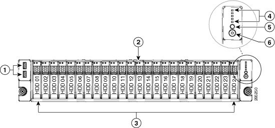
Figure 1-1 shows the front panel features of the Small Form-Factor drives version of the server. This version of the server can be ordered with either a 16-drive direct-connect backplane or a 24-drive backplane with an expander. When the 16-drive backplane is installed, only the first 16 drive bays are used.
Figure 1-1 Cisco UCS C24 Server (Small Form Factor Drives) Front Panel Features
|
|
|
||
|
|
|
||
|
|
|
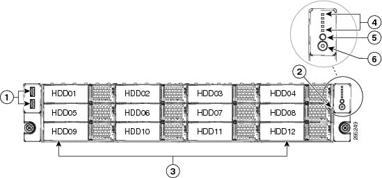
Figure 1-2 shows the front panel features of the Large Form Factor drives version of the server. This version of the server has a 12-drive backplane with an expander. For definitions of all LED states, see Status LEDs and Buttons.
Figure 1-2 Cisco UCS C24 Server (Large Form Factor Drives) Front Panel Features
|
|
|
Network activity LED |
|
|
|
|
||
|
|
|
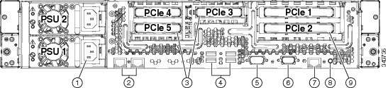
Figure 1-3 shows the rear panel features of the server (identical for all versions of the server). For definitions of all LED states, see Status LEDs and Buttons.
Figure 1-3 Cisco UCS C24 Server Rear Panel Features
|
|
|
||
|
|
|
||
|
|
PCIe slots 3, 4, and 5 on riser 2 |
|
|
|
|
|
PCIe slots 1 and 2 on riser 1 |
|
|
|
|
Table 1-1 lists a summary of server features.
The server provides 12 DIMM1 sockets on the motherboard. |
|
Pilot III BMC, running Cisco Integrated Management Controller (CIMC) firmware. Depending on your CIMC settings, the CIMC can be accessed through the |
|
The 1-Gb Base-T Ethernet LAN ports support the wake-on-LAN (WoL) standard. |
|
Two power supplies: Both either 450 W each or 650 W each. Do not mix power supply types. Redundant as 1+1. See Power Specifications. |
|
This server supports the advanced configuration and power interface (ACPI) 4.0 standard. |
|
Five horizontal PCIe4 expansion slots on two risers. See PCIe Slots for specifications of the slots. |
|
The bus slots in this server support the InfiniBand architecture. |
|
Drives are installed into front-panel drive bays that provide hot-pluggable access. There are two versions of the server front panel and backplane:
|
|
The server has one internal USB 2.0 socket on the motherboard that you can use with a USB thumb drive for additional storage. The server can be ordered with an optional blank 8-GB Cisco USB Flash Drive pre-installed in the internal USB port. |
|
For a list of RAIDRAID Controller Considerations. |
|
There are two mounting points inside the chassis that can be used for the SuperCap power module that is used with LSI MegaRAID-CV card. |
|
Matrox G200e video controller. Resolution up to 1920 x1200, 16bpp at 60 Hz. Up to 256 MB of video memory. |
|
|
 Feedback