Cisco Nexus Virtual Services Appliance Software Configuration Guide, Release 4.2(1)SP1(5.1)
Bias-Free Language
The documentation set for this product strives to use bias-free language. For the purposes of this documentation set, bias-free is defined as language that does not imply discrimination based on age, disability, gender, racial identity, ethnic identity, sexual orientation, socioeconomic status, and intersectionality. Exceptions may be present in the documentation due to language that is hardcoded in the user interfaces of the product software, language used based on RFP documentation, or language that is used by a referenced third-party product. Learn more about how Cisco is using Inclusive Language.
- Updated:
- September 10, 2014
Chapter: Overview
- Information About Cisco Nexus Virtual Services Appliance
- Comparison with a Virtual Machine
- Cisco Integrated Management Controller
- Virtual Service Blades
- Uplinks
- Traffic Classification
- Options for Connecting to the Network
- Topology 5: Flexible Network Uplink Configuration
- Topology 1: Single Uplink
- Topology 2: Two Uplinks—1) Management and Control and 2) Data
- Topology 3: Two Uplinks—1) Management and 2) Control and Data
- Topology 4: Three Uplinks—1) Management, 2) Control, and 3) Data
Overview
This chapter describes the Cisco Nexus Virtual Services Appliance product family and hosted virtual service blades. This chapter includes the following sections:
Information About Cisco Nexus Virtual Services Appliance
The Cisco Nexus Virtual Services Appliance product family includes Cisco Nexus 1010, Cisco Nexus 1010-X, Cisco Nexus 1110-S, and Cisco Nexus 1110-X.
The Cisco Nexus Virtual Services Appliance product family are networking appliances that can hosts up to six Cisco Nexus 1000V virtual service blades (VSBS) on Cisco Nexus 1010 and Cisco Nexus 1110-S and upto ten Cisco Nexus 1000V virtual service blades (VSBS) on Cisco Nexus 1010-X and Cisco Nexus 1110-X. Cisco Nexus Virtual Services Appliance product family supports VSBs like Cisco Nexus 1000V Virtual Supervisor Module (VSM), Network Analysis Module (NAM), and Virtual Security Gateway(VSG).
The Cisco Nexus Virtual Services Appliance provides dedicated hardware for the VSM. VSMs that were hosted on VMware virtual machines can now be hosted on a Cisco Nexus Virtual Services Appliance. This allows you to install and manage the VSM like a standard Cisco switch. The services (VSM, VSG or NAM) managed by the Cisco Nexus Virtual Services Appliance product family are called virtual service blades (VSBs). For more information about VSBs, see the “Virtual Service Blades” section.
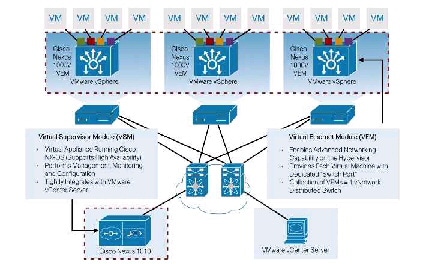
Figure 1-1 shows how the Cisco Nexus Virtual Services Appliance hosts a Cisco Nexus 1000V VSM and its VEMs in your network.
Figure 1-1 Cisco Nexus Virtual Services Appliance Architecture
Cisco Nexus Virtual Services Appliance High Availability
Cisco Nexus Virtual Services Appliance supports High Availability. Two Cisco Nexus Virtual Services Appliance can form a HA pair to provide high availability. If control connectivity is lost for the Cisco Nexus Virtual Services Appliance, but management connectivity is preserved, the active Cisco Nexus Virtual Services Appliance reloads the standby once. The standby comes up in wait state until control connectivity is restored. In a HA pair, the active and standby Cisco Nexus Virtual Services Appliance uses control connectivity to synchronize data.
Cisco Nexus Virtual Services Appliance supports the following two forms of high availability concurrently:
- Active-Standby in Management Deployment: The active Cisco Nexus Virtual Services Appliance is reachable over the network and majority of the commands are supported only on the active Cisco Nexus Virtual Services Appliance. Standby Cisco Nexus Virtual Services Appliance is not reachable over the IP network, but can be accessed through the active Cisco Nexus Virtual Services Appliance or directly through serial connection.
- Active-Active in VSB Deployment: When you deploy a VSB on Cisco Nexus Virtual Services Appliance, you can deploy the VSB on either the active or the standby Cisco Nexus Virtual Services Appliance and the VSBs can be active on both the active and standby Cisco Nexus Virtual Services Appliance. This helps balance the distribution of traffic as well as reduce the potential fault domain.
Figure 1-2 shows the HA components and the communication links between them.
Figure 1-2 Cisco Nexus Virtual Services Appliance HA Components and Communication Links

Comparison with a Virtual Machine
Table 1-1 compares running a VSM on a Cisco Nexus Virtual Services Appliance with running a VSM on a virtual machine.
|
|
|
|
|
|
|
|---|---|---|---|---|---|
3841 |
6402 |
||||
|
|
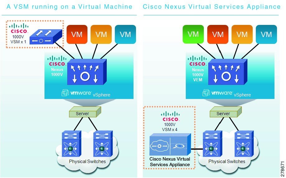
Figure 1-3 compares running a VSM on a Cisco Nexus Virtual Services Appliance with running a VSM on a virtual machine.
Figure 1-3 VM and Cisco Nexus Virtual Services Appliance Comparison
Cisco Integrated Management Controller
The Cisco Integrated Management Controller (CIMC) is a software interface included with the Cisco Nexus Virtual Services Appliance. CIMC allows you to configure serial over LAN (SoL) access and set up remote management in the event the device becomes unreachable. For more information about remote management, see the Cisco Nexus Virtual Services Appliance Software Installation and Upgrade Guide, Release 4.2(1)SP1(5.1) .
When installing the Cisco Nexus Virtual Services Appliance, you have the option to configure the CIMC interface. To configure the CIMC software while installing the Cisco Nexus Virtual Services Appliance, see the Cisco Nexus Virtual Services Appliance Hardware Installation Guide .
Virtual Service Blades
The services (VSM, NAM, VSG) hosted, created, and managed by the Cisco Nexus Virtual Services Appliance product family are called virtual service blades (VSBs). Cisco Nexus 1110-S can hosts up to six virtual service blades (VSBs) and Cisco Nexus 1110-X can host upto 10 VSBs.
VSBs are created using ISO or OVA image files found in the Cisco Nexus Virtual Services Appliance bootflash repository. The ISO defines the following for a VSB:
- Required number of interfaces
- Required hard disk emulation
- Disk and RAM defaults
- Type of virtual service blade
For more information about VSBs, see the “Configuring Virtual Service Blades” section.
The Cisco Nexus 1110-S VSA maximum supported configuration (up to six VSBs total) is either:
- 6 Cisco Nexus 1000V VSMs, each capable of managing 64 VMware ESX or ESXi hosts for a total of 384 VMware ESX or ESXi hosts
- 6 Cisco Virtual Security Gateway (VSG) VSBs
The Cisco Nexus 1110-X VSA maximum supported configuration (up to 10 VSBs total) is either:
Uplinks
This section describes the uplinks that you connected during your installation of the hardware. For more information about these connections and the prerequisites for the switches that are upstream from your Cisco Nexus Virtual Services Appliance, see the Cisco Nexus Virtual Services Appliance Hardware Installation Guide .
This section includes the following topics:
- Traffic Classification
- Options for Connecting to the Network
- Topology 5: Flexible Network Uplink Configuration
- Topology 1: Single Uplink
- Topology 2: Two Uplinks—1) Management and Control and 2) Data
- Topology 3: Two Uplinks—1) Management and 2) Control and Data
- Topology 4: Three Uplinks—1) Management, 2) Control, and 3) Data
Traffic Classification
Table 1-2 lists and describes the classes of network traffic carried on the Cisco Nexus Virtual Services Appliance uplinks:
Options for Connecting to the Network
Table 1-3 describes the available uplink configurations.
You choose the type of uplink for your network. See the Cisco Nexus Virtual Services Appliance Software Installation and Upgrade Guide, Release 4.2(1)SP1(5.1) for more information.

Note![]() Once you configure an uplink type, the only way to modify it is to reload the software.
Once you configure an uplink type, the only way to modify it is to reload the software.
Topology 5: Flexible Network Uplink Configuration
Flexible network configuration offers complete flexibility to connect Cisco Nexus 1110-S or Cisco Nexus 1110-X to the network, and allowing flexible deployment of the VSBs on the Cisco Nexus Virtual Services Appliance product family. Flexible configuration thus enables appropriate traffic segregation policies like VSB traffic segregation. The default flexible network uplink configuration is the basic configuration with each physical port acting as an individual uplink. See Figure 1-4. You can then make changes to the default configuration by adding ports to a port channel or by assigning uplinks to a VSB interface.
For more information on flexible network uplink configuration, see Flexible Network Uplink Configuration.
Figure 1-4 Topology 5: Without vPC or VSS (Default)
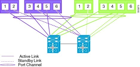
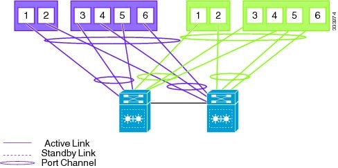
Figure 1-5 Topology 5: With vPC or VSS (Default)
Topology 1: Single Uplink
In this topology, your Cisco Nexus Virtual Services Appliance pair connects to your network in two uplinks as shown in the following figures:
- Figure 1-6, without vPC or VSS
- Figure 1-7, with vPC or VSS
For detailed information about connecting uplinks, see the Cisco Nexus Virtual Services Appliance Hardware Installation Guide .
Figure 1-6 Topology 1: Single Uplink Without vPC or VSS
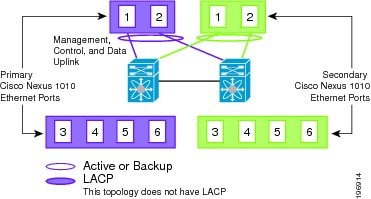
Figure 1-7 Topology 1: Single Uplink With vPC or VSS
Topology 2: Two Uplinks—1) Management and Control and 2) Data
In topology 2, six Gigabit Ethernet ports on each Cisco Nexus Virtual Services Appliance create two uplinks. The ports in each Cisco Nexus Virtual Services Appliance internally form a port channel and network traffic is load balanced based on the source MAC algorithm.
LACP must be configured on the upstream switches connecting to ports 3, 4, 5, and 6.
In topology 2, your Cisco Nexus Virtual Services Appliance pair connects to your network in two uplinks as shown in the following figures:
- Figure 1-8, without vPC or VSS
- Figure 1-9, with vPC or VSS
For detailed information about connecting uplinks, see the Cisco Nexus Virtual Services Appliance Hardware Installation Guide .
Figure 1-8 Topology 2: Two Uplinks Without vPC or VSS—
1) Management and Control Uplink, and 2) Data Uplink
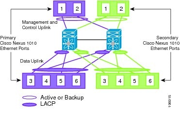
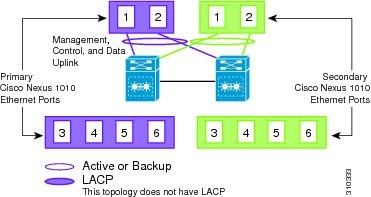
Figure 1-9 Topology 2: Two Uplinks With vPC or VSS—
1) Management and Control Uplink, and 2) Data Uplink
Topology 3: Two Uplinks—1) Management and 2) Control and Data
In topology 3, the ports in each Cisco Nexus Virtual Services Appliance internally form a port channel and network traffic is load balanced based on the source MAC algorithm.
LACP must be configured on the upstream switches connecting to ports 3, 4, 5, and 6.
In topology 3, your Cisco Nexus Virtual Services Appliance pair connects to your network in two uplinks as shown in the following figures:
- Figure 1-10, without vPC or VSS
- Figure 1-11, with vPC or VSS
For detailed information about connecting uplinks, see the Cisco Nexus Virtual Services Appliance Hardware Installation Guide .
Figure 1-10 Topology 3: Two Uplinks Without vPC or VSS—
1) Management Uplink, and 2) Control and Data Uplink
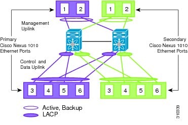
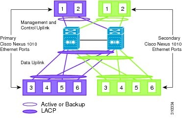
Figure 1-11 Topology 3: Two Uplinks With vPC or VSS—
1) Management Uplink, and 2) Control and Data Uplink

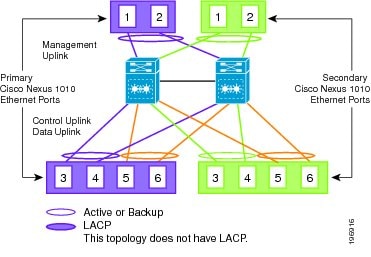
Topology 4: Three Uplinks—1) Management, 2) Control, and 3) Data
In topology 4, six Gigabit Ethernet ports on each Cisco Nexus Virtual Services Appliance create three uplinks as shown in one of the following figures:
- Figure 1-12, without vPC or VSS
- Figure 1-13, with vPC or VSS
For detailed information about connecting uplinks, see the Cisco Nexus Virtual Services Appliance Hardware Installation Guide .
Figure 1-12 Topology 4: Three Uplinks Without vPC or VSS
1) Management, 2) Control, and 3) Data
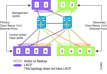
Figure 1-13 Topology 4: Three Uplinks With vPC or VSS
1) Management, 2) Control, and 3) Data
 Feedback