Cisco VG350 Voice Gateway Hardware Installation Guide
Bias-Free Language
The documentation set for this product strives to use bias-free language. For the purposes of this documentation set, bias-free is defined as language that does not imply discrimination based on age, disability, gender, racial identity, ethnic identity, sexual orientation, socioeconomic status, and intersectionality. Exceptions may be present in the documentation due to language that is hardcoded in the user interfaces of the product software, language used based on RFP documentation, or language that is used by a referenced third-party product. Learn more about how Cisco is using Inclusive Language.
- Updated:
- March 27, 2014
Chapter: Cable Specifications and Information
Cable Specifications and Information
This appendix provides the connector and pinout information you need for making or purchasing cables used with Cisco VG350 Voice Gateway. To order cables from Cisco, see the “$paratext>” section . This appendix contains the following sections:
- Console and Auxiliary Port Cables and Pinouts
- Gigabit Ethernet Port Pinouts (RJ-45)
- Analog Voice Multiport Pinouts (RJ-21X/CA21A)
The following list shows you which table to see for pinout information:
Console and Auxiliary Port Cables and Pinouts
Your Cisco VG350 Voice Gateway comes with the cable and adapters you need to connect a PC, an ASCII terminal, or a modem to your Cisco VG350 Voice Gateway. The cable kit includes:
- RJ-45-to-RJ-45 rollover cable
- RJ-45-to-DB-9 adapter cable for console connection
- RJ-45-to-DB-25 adapter cable for modem connection
The following illustrations and tables provide cable pinout information:
- Console port to a PC—See Table A-1 and Table A-4
- Console port to an ASCII terminal—See Table A-2 and Table A-4
- Auxiliary port to a modem—See Table A-3 and Table A-4
The console port is configured as data communications equipment (DCE); the auxiliary port is configured as data terminal equipment (DTE). Both are asynchronous serial ports and use RJ-45 connectors.
Console Port to PC
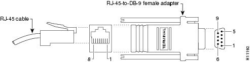
Figure A-1 shows the RJ-45-to-RJ-45 rollover cable assembly and the RJ-45-to-DB-9 female DTE adapter (labeled TERMINAL); Table A-1 lists the pinouts.
Figure A-1 Console Port to PC—Cable and Adapter
11 |
|||||
|
1.Pin 1 is connected to pin 8 inside the Cisco VG350 Voice Gateway. |
Console Port to ASCII Terminal
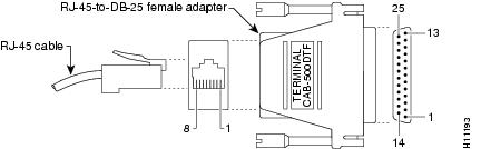
Figure A-2 shows the RJ-45-to-RJ-45 rollover cable assembly and the RJ-45-to-DB-25 female DTE adapter (labeled TERMINAL); Table A-2 lists the pinouts.
Figure A-2 Console Port to ASCII Terminal—Cable and Adapter
12 |
|||||
|
2.Pin 1 is connected to pin 8 inside the Cisco VG350 Voice Gateway. |
Auxiliary Port to Modem
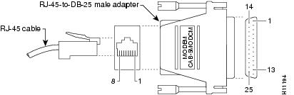
Figure A-3 shows the RJ-45-to-RJ-45 rollover cable assembly and the RJ-45-to-DB-25 male DCE adapter (labeled MODEM); Table A-3 lists the pinouts.
Figure A-3 Auxiliary Port to Modem—Cable and Adapter
Alternative Connections to Terminal and Modem
Your Cisco VG350 Voice Gateway ships with an RJ-45-to-RJ-45 rollover cable and two adapters for connection to a PC, a terminal, or a modem. If you want to use an RJ-45 straight-through cable or other adapters, see Table A-4 for usable cable and adapter combinations.
|
3.An octal cable or RJ-45 breakout cable is equivalent to a rollover cable. 4.Modify the DB-25 adapter by removing the wire in pin 6 and placing it in the pin 8 position. |
Gigabit Ethernet Port Pinouts (RJ-45)
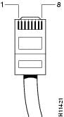
Figure A-4 shows the RJ-45 connector wiring for the Gigabit Ethernet cable; Figure A-4 lists the pinouts.

Note Pinout shown is for category 3, 4, or 5 10/100BASE-T connection to an Gigabit Ethernet switch.
Figure A-4 RJ-45 Connector Wiring
Pin5
|
|
|---|---|
Analog Voice Multiport Pinouts (RJ-21X/CA21A)
Figure A-5 shows the RJ-21 connector wiring for the cable used for the multiport analog voice interface.
Figure A-5 RJ-21 Connector Wiring
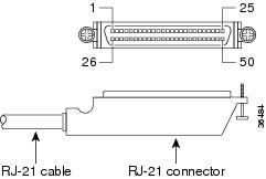
Table A-6 lists the pinouts for the RJ-21 connector.
 Feedback