- Preface
- Product Overview
- Preparing for Installation
- Installing the Cisco uBR10012 Universal Broadband Router
- Troubleshooting the Installation
- Maintaining the Cisco uBR10012 Router
- Technical Specifications
- Cable Specifications
- Frequency Allocation
- Manufacturers for Headend Provisioning Requirements
- Glossary
Cisco uBR10012 Universal Broadband Router Hardware Installation Guide
Bias-Free Language
The documentation set for this product strives to use bias-free language. For the purposes of this documentation set, bias-free is defined as language that does not imply discrimination based on age, disability, gender, racial identity, ethnic identity, sexual orientation, socioeconomic status, and intersectionality. Exceptions may be present in the documentation due to language that is hardcoded in the user interfaces of the product software, language used based on RFP documentation, or language that is used by a referenced third-party product. Learn more about how Cisco is using Inclusive Language.
- Updated:
- July 2, 2012
Chapter: Preparing for Installation
Preparing for Installation
Before you install the Cisco uBR10012 universal broadband router, consider:
- The power and cabling requirements that must be in place at your installation sites
- The equipment required to install the router
- The environmental conditions your installation site must meet to maintain normal operation
This chapter guides you through the process of preparing for your router installation.
Do not unpack the system until you are ready to install it. Keep the chassis in the shipping container to prevent accidental damage until you determine an installation site.

Note![]() The Cisco uBR10012 router (using DC power supplies) is not shipped with wiring to connect to a DC power source. You must provide input, return, and earthing (grounding) wiring at the site, and install and protect the wiring in accordance with local and national wiring regulations (see Table 3-4).
The Cisco uBR10012 router (using DC power supplies) is not shipped with wiring to connect to a DC power source. You must provide input, return, and earthing (grounding) wiring at the site, and install and protect the wiring in accordance with local and national wiring regulations (see Table 3-4).
Safety
When you install the Cisco uBR10012 router, observe all of the following caution and warning statements. For warning translations, refer to the regulatory compliance and safety documentation at the following URL:
http://www.cisco.com/en/US/docs/cable/cmts/ubr10012/regulatory/compliance/ub10rcsi.html
The following guidelines will help ensure your safety and protect the equipment. However, these guidelines may not cover all potentially hazardous situations you may encounter during system installation, so be alert.
- The installation of your Cisco uBR10012 router must comply with national and local electrical codes. In the United States, this means the National Fire Protection Association (NFPA) 70, United States National Electrical Code. In Canada, Canadian Electrical Code, part I, CC22.1. In other countries, International Electrotechnical Commission (IEC) 364, part 1 through part 7.
- Review the safety warnings listed in the regulatory compliance and safety documentation before installing, configuring, or performing maintenance on the product.
- Always disconnect power at the source before you install or remove a chassis.
- Never attempt to lift an object that might be too heavy to lift safely by yourself.
- Keep the chassis area clear and as dust free as possible during and after installation.
- Keep tools and chassis components away from walk areas.
- Do not wear loose clothing, jewelry (including rings and chains), or other items that could get caught in the chassis.
- The Cisco uBR10012 router operates safely when it is used in accordance with its marked electrical ratings and product usage instructions.

Warning![]() Only trained and qualified personnel should be allowed to install, replace, or service this equipment. Statement 1030.
Only trained and qualified personnel should be allowed to install, replace, or service this equipment. Statement 1030.
Preventing Electrostatic Discharge Damage
Electrostatic discharge (ESD) damage, which occurs when electronic cards or components are improperly handled, can result in complete or intermittent failures. The performance routing engine (PRE), and all line cards consist of a printed circuit card that is fixed in a metal carrier. Electromagnetic interference (EMI) shielding and connectors are integral components of the carrier. Although the metal carrier helps to protect the cards from ESD, use an antistatic strap each time you handle the modules. Handle the carriers by the edges only; never touch the cards or connector pins.

Following are guidelines for preventing ESD damage:
- Always use an ESD-preventive wrist or ankle strap and ensure that it makes good skin contact. Before removing a card from the chassis, connect the equipment end of the strap to a bare metal, unpainted surface on the chassis or rackmount.
- Handle line cards by the faceplates and carrier edges only; avoid touching the card components or any connector pins.
- When removing a line card, place the removed module component-side-up on an antistatic surface or in a static-shielding bag. If the module will be returned to the factory, immediately place it in a static-shielding bag.
- Avoid contact between the modules and clothing. The wrist strap protects the card from ESD voltages on the body only; ESD voltages on clothing can still cause damage.
Chassis-Lifting Guidelines
The Cisco uBR10012 chassis is not intended to be moved frequently. When fully populated, the Cisco uBR10012 system weighs approximately 230 pounds. A depopulated chassis weighs approximately 55 pounds.
When moving the chassis, use the following guidelines to prevent injury and damage to the equipment:
- Before you install the system, ensure that your site is properly prepared so you can avoid having to move the chassis later to accommodate power sources and network connections.
- A fully populated chassis should be moved only with a hydraulic lift or forklift. Do not attempt to manually lift a populated chassis.
- Two people are required to safely move a depopulated chassis. This should be done by using the handles on each side of the chassis.
Warning![]() To prevent personal injury or damage to the chassis, never attempt to lift or tilt the chassis using the handles on modules (such as power supplies, fans, or cards); these types of handles are not designed to support the weight of the unit. Statement 1032
To prevent personal injury or damage to the chassis, never attempt to lift or tilt the chassis using the handles on modules (such as power supplies, fans, or cards); these types of handles are not designed to support the weight of the unit. Statement 1032
- Never attempt to lift even a depopulated chassis by yourself. Because of the size and weight of the chassis, use at least two people to safely lift and move it without causing injury or damaging the equipment.
- To prevent injury, keep your back straight and lift with your legs, not your back.
- Ensure that your footing is solid, and balance the weight of the chassis between your feet.
- Lift the chassis slowly; never move suddenly or twist your body as you lift.
- Keep your back straight and lift with your legs, not your back. If you must bend down to lift the chassis, bend at the knees, not at the waist, to reduce the strain on your back muscles.
- If you have to move a fully populated chassis and you do not have a hydraulic lift or forklift available, you must first remove the following components from the chassis:
–![]() AC or DC power entry modules (PEMs)
AC or DC power entry modules (PEMs)
In a fully loaded chassis, these components weigh approximately 170 pounds, so removing them allows the chassis to be safely moved with two people. The components can then be reinserted after the chassis has been moved and installed. See Chapter 5, “Maintaining the Cisco uBR10012 Router” for instructions on removing these components.
Electrical Safety
All system components are hot-swappable. They are designed to be removed and replaced while the system is operating without presenting an electrical hazard or damage to the system.
Follow these basic guidelines when you are working with any electrical equipment:
- Before beginning any procedures requiring access to the chassis interior, locate the emergency power-off switch for the room in which you are working.
- Disconnect all power and external cables before installing or removing a chassis.
- Do not work alone when potentially hazardous conditions exist.
- Never assume that power has been disconnected from a circuit; always check.
- Do not perform any action that creates a potential hazard to people or makes the equipment unsafe. Never install equipment that appears damaged.
- Carefully examine your work area for possible hazards such as moist floors, ungrounded power extension cables, and missing safety grounds.
Warning![]() When installing or replacing the unit, the ground connection must always be made first and disconnected last. Statement 1046
When installing or replacing the unit, the ground connection must always be made first and disconnected last. Statement 1046
Warning![]() Do not work on the system or connect or disconnect cables during periods of lightning activity. Statement 1001
Do not work on the system or connect or disconnect cables during periods of lightning activity. Statement 1001
Warning![]() Read the installation instructions before you connect the system to its power source. Statement 1004
Read the installation instructions before you connect the system to its power source. Statement 1004
Site Requirements
This section provides information for environmental, power, cabling, and rack mounting requirements. Be sure that you have met all of these requirements before you install your Cisco uBR10012 router.
Warning![]() This unit is intended for installation in restricted access areas. A restricted access area can be accessed only through the use of a special tool, lock and key, or other means of security. Statement 1017
This unit is intended for installation in restricted access areas. A restricted access area can be accessed only through the use of a special tool, lock and key, or other means of security. Statement 1017
Environmental Site Requirements
The environmental monitoring functionality in the Cisco uBR10012 router protects the system and components from potential damage from excessive voltage and temperature conditions. To ensure normal operation and avoid unnecessary maintenance, plan your site configuration and prepare your site before installation. After installation, make sure the site maintains an ambient temperature of 41°F through 104°F (5°C through 40°C), and keep the area around the chassis as free from dust as is practical.
Planning a proper location for the Cisco uBR10012 router and the layout of your equipment rack or wiring closet is essential for successful system operation. Equipment placed too close together or inadequately ventilated can cause system excessive temperature conditions. In addition, chassis panels made inaccessible by poor equipment placement can make system maintenance difficult.
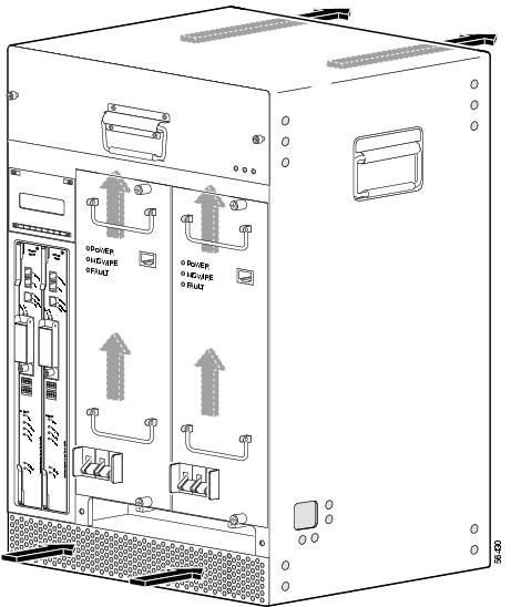
When you plan the location and layout of your equipment rack or wiring closet, you need to consider how air flows through your router. The Cisco uBR10012 router draws cooling air in through the intake vent on the front of the chassis and moves the air across the internal components and out the exhaust vents on the top rear of the chassis (see Figure 2-1).
Temperature sensors on the PRE monitor the internal air temperature and send warning messages and an alarm condition when the internal air temperature approaches a specified threshold.
The front bottom and top rear of the chassis must remain unobstructed to ensure adequate airflow and prevent overheating inside the chassis. Maintain a minimum clearance of 3 in. (7.62 cm) from the vents on the front and back of the chassis to allow for adequate airflow. Do not place the chassis where heated exhaust air from other systems could enter the air intake vent at the bottom front, as this could cause overheating of the system.
In addition, allow for approximately 3 to 4 ft (91.44 cm to 121.92 cm) clearance at the front and rear of the chassis for cabling and normal system maintenance.
Warning![]() Blank faceplates and cover panels serve three important functions: they prevent exposure to hazardous voltages and currents inside the chassis; they contain electromagnetic interference (EMI) that might disrupt other equipment; and they direct the flow of cooling air through the chassis. Do not operate the system unless all cards, faceplates, front covers, and rear covers are in place. Statement 1029
Blank faceplates and cover panels serve three important functions: they prevent exposure to hazardous voltages and currents inside the chassis; they contain electromagnetic interference (EMI) that might disrupt other equipment; and they direct the flow of cooling air through the chassis. Do not operate the system unless all cards, faceplates, front covers, and rear covers are in place. Statement 1029
To avoid problems during installation and ongoing operation, follow these general precautions when you plan the equipment locations and connections:
- Use the show environment command regularly to check the internal system status. The environmental monitor continually checks the interior chassis environment; it provides warnings for high temperature and creates reports on any occurrences. If warning messages are displayed, take immediate action to identify the cause and correct the problem.
- Keep the Cisco uBR10012 router off of the floor and out of areas that collect dust.
- Follow ESD prevention procedures (see “Preventing Electrostatic Discharge Damage” section) to avoid damage to equipment. Damage from static discharge can cause immediate or intermittent equipment failure.
- Ensure that the PRE modules, line cards, blank covers, power supplies, and any power supply covers are in place and secure. The fans direct cooling air throughout the chassis interior; a loose component or empty slot can redirect the airflow away from active components.
Figure 2-1 Cooling Air Path for the Cisco uBR10012
Temperature and Humidity Requirements
Table 2-1 lists the operating and nonoperating environmental site requirements. The ranges listed are those within which the Cisco uBR10012 router continues to operate; however, a measurement that is approaching the minimum or maximum of a range indicates a potential problem. You can maintain normal operation by anticipating and correcting environmental anomalies before they approach a maximum operating range.
|
|
|
|
|---|---|---|
Power Guidelines
Follow these precautions and recommendations when planning power connections to the Cisco uBR10012 router:
- Ensure that you are using proper cables and have circuit breakers installed.
- Check the power at your site before installation and periodically after installation to ensure that you are receiving clean power. Install a power conditioner if necessary.
- Provide proper grounding to avoid damage from lightning and power surges.
- Use a 6-AWG, copper ground conductor (minimum requirement) when attaching the chassis ground to a central office or other interior ground system. An insulation rating of 167° Fahrenheit (75° Celsius) is required for the 6-AWG wire for 3000 W of power.
Warning![]() This product requires short-circuit (overcurrent) protection, to be provided as part of the building installation. Install only in accordance with national and local wiring regulations. Statement 1045
This product requires short-circuit (overcurrent) protection, to be provided as part of the building installation. Install only in accordance with national and local wiring regulations. Statement 1045
Warning![]() A readily accessible two-poled disconnect device must be incorporated in the fixed wiring. Statement 1022
A readily accessible two-poled disconnect device must be incorporated in the fixed wiring. Statement 1022
Power Connection Guidelines for DC-Powered Systems
The DC-input power supply allows the Cisco uBR10012 router to operate on either –48 or –60 VDC systems. Both these power supplies can operate with an input from –40.5 to —72 VDC with no harm; however, the input should be restricted to the nominal ranges defined in Table 2-2 to maintain safety extra-low voltage (SELV) compliance, and to deliver the rated power at the allowed current levels. Table 2-2 summarizes the power output, DC-input voltage, and DC-input current values for the DC PEM.
Table 2-2 Power Output, DC-input Voltage, and DC-input Current Values for the DC PEM
|
|
|
|
|
|
|
1.The 34- part number is listed on the compliance label of the DC PEM. |
Warning![]() Connect the unit only to DC power source that complies with the safety extra-low voltage (SELV) requirements in IEC 60950 based safety standards. Statement 1033
Connect the unit only to DC power source that complies with the safety extra-low voltage (SELV) requirements in IEC 60950 based safety standards. Statement 1033
Note![]() The Cisco uBR10012 router (using DC power supplies) is not shipped with wiring to connect to a DC power source. You must provide input, return, and earthing (grounding) wiring at the site, and install and protect the wiring in accordance with local and national wiring regulations. The Cisco uBR10012 router input DC terminal block accepts a minimum of 6-AWG wire. An insulation rating of 167° Fahrenheit (75° Celsius) is required for the 6-AWG wire for 3000W of power.
The Cisco uBR10012 router (using DC power supplies) is not shipped with wiring to connect to a DC power source. You must provide input, return, and earthing (grounding) wiring at the site, and install and protect the wiring in accordance with local and national wiring regulations. The Cisco uBR10012 router input DC terminal block accepts a minimum of 6-AWG wire. An insulation rating of 167° Fahrenheit (75° Celsius) is required for the 6-AWG wire for 3000W of power.
See Appendix A, “Technical Specifications,” for system power specifications, including input voltage and operating frequency ranges.
Warning![]() Connect the unit only to DC power source that complies with the safety extra-low voltage (SELV) requirements in IEC 60950 based safety standards. Statement 1033
Connect the unit only to DC power source that complies with the safety extra-low voltage (SELV) requirements in IEC 60950 based safety standards. Statement 1033
Plant Wiring Guidelines
When planning the location of the new system, consider the distance limitations for signaling, EMI, and connector compatibility, as described in the following sections.
Warning![]() This product requires short-circuit (overcurrent) protection, to be provided as part of the building installation. Install only in accordance with national and local wiring regulations. Statement 1045
This product requires short-circuit (overcurrent) protection, to be provided as part of the building installation. Install only in accordance with national and local wiring regulations. Statement 1045
Interference Considerations
When wires are run for any significant distance in an electromagnetic field, interference can occur between the field and the signals on the wires. This fact has two implications for the construction of plant wiring:
- Bad wiring practice can result in radio interference emanating from the plant wiring.
- Strong EMI, especially when it is caused by lightning or radio transmitters, can destroy the signal drivers and receivers in the Cisco uBR10012 router, and can even create an electrical hazard by conducting power surges through lines and into equipment. (Review the safety warnings in the “Preventing Electrostatic Discharge Damage” section.)
Note![]() To predict and remedy strong EMI, you may also need to consult experts in radio frequency interference (RFI).
To predict and remedy strong EMI, you may also need to consult experts in radio frequency interference (RFI).
If you use twisted-pair cable in your plant wiring with a good distribution of grounding conductors, the plant wiring is unlikely to emit radio interference. If you exceed the recommended distances, use a high-quality twisted-pair cable with one ground conductor for each data signal when applicable.
If wires exceed recommended distances, or if wires pass between buildings, give special consideration to the effect of a lightning strike in your vicinity. The electromagnetic pulse caused by lightning or other high-energy phenomena can easily couple enough energy into unshielded conductors to destroy electronic devices. If you have had problems of this sort in the past, you may want to consult experts in electrical surge suppression and shielding.
Cabling Guidelines
The size of your networks and the distances between connections depend on the type of signal, the signal speed, and the transmission media (the type of cabling used to transmit the signals). For example, standard coaxial cable has a greater channel capacity than twisted-pair cabling. The distance and rate limits in the following descriptions are the IEEE recommended maximum speeds and distances for signaling; however, you can usually get good results at speeds and distances far greater than these. For example, the recommended maximum rate for V.35 is 2 Mbps, but it is commonly used at 4 Mbps without any problems. If you understand the electrical problems that might arise and can compensate for them, you should get good results with rates and distances greater than those shown here; however, do so at your own risk.
When preparing your site for network connections to the Cisco uBR10012 router, you must consider a number of factors related to each type of interface:
- The type of cabling required for each type (fiber, thick or thin coaxial, foil twisted-pair, or unshielded twisted-pair cabling)
- Distance limitations for each signal type
- The specific cables you need to connect each interface
- Any additional interface equipment you need, such as transceivers, hubs, switches, modems, channel service units (CSUs), or data service units (DSUs)
The extent of your network and the distances between network interface connections depend in part on the following factors:
The distance and rate limits referenced in the following sections are the IEEE-recommended maximum speeds and distances for signaling purposes. Use this information as a guideline in planning your network connections prior to installing the Cisco uBR10012 router.
Ethernet and Fast Ethernet Connections
The maximum distances for Ethernet and Fast Ethernet network segments and connections depend on the type of transmission cable being used. The terms 10Base-T and 100Base-T are industry shorthand nomenclature for the following:
- 10 Mbps transmission rate (10), or 100 Mbps transmission rate (100)
- Using baseband technology (Base)
- By means of twisted pair wires (T)
Table 2-3 shows the maximum transmission distances between stations for Ethernet and Fast Ethernet connections.
|
|
|
|
|
|---|---|---|---|
Fiber-Optic Connections
The specifications for single-mode, fiber-optic transmissions are outlined in Table 2-4 .
|
|
|
|
|
|---|---|---|---|
Rack-Mounting Considerations
The Cisco uBR10012 router should be rack-mounted for proper operation and maintenance. The rack-mounting hardware included with chassis is suitable for standard 19-inch equipment racks and telco-type racks. Optional hardware is available from third-party vendors for mounting in a 23-inch equipment rack.
Mounting Guidelines
Warning![]() The chassis should be mounted on a rack that is permanently affixed to the building. Statement 1049
The chassis should be mounted on a rack that is permanently affixed to the building. Statement 1049
When planning your rack installation, consider the following guidelines:
- Allow sufficient clearance around the rack for maintenance. You need 24 in. (61 cm) of clearance to remove and replace system components.
- If the rack is provided with stabilizing devices, install the stabilizers before mounting or servicing the unit in the rack.
- Always install heavier equipment in the lower half of a rack to maintain a low center of gravity and prevent the rack from falling over.
- When mounting this unit in a partially filled rack, load the rack from the bottom to the top, with the heaviest component at the bottom of the rack.
Note![]() This unit should be mounted at the bottom of the rack if it is the only unit in the rack.
This unit should be mounted at the bottom of the rack if it is the only unit in the rack.
- If you plan to use an equipment shelf, ensure that the shelf is constructed to support the weight and dimensions of the chassis. Use the rack-mount kit designed for the Cisco uBR10012 router.
- To mount the chassis between two 19-inch posts or rails, the inner clearance (the width between the inner sides of the two posts or rails) must be at least 17.3 in. (44 cm).
Note![]() The height of the chassis is 31.25 in. (79.4 cm).
The height of the chassis is 31.25 in. (79.4 cm).
- When mounting the chassis in 4-post or telco racks, be sure to use all the screws and brackets provided to secure the chassis to the rack posts.
- Install the forward rack-mount brackets before you install the chassis in the rack; and then install the rear brackets.
- If you are also using the optional AC-input power shelf, it should be installed immediately below the Cisco uBR10012 chassis for power cabling convenience. However, install the AC-input power shelf after you install the chassis.
- Ensure that the router is connected to earth ground during normal use.
- Frame ground should be tied to the single building point ground, or the closest return point to building ground.
Warning![]() This equipment must be grounded. Never defeat the ground conductor or operate the equipment in the absence of a suitably installed ground conductor. Contact the appropriate electrical inspection authority or an electrician if you are uncertain that suitable grounding is available. Statement 1024
This equipment must be grounded. Never defeat the ground conductor or operate the equipment in the absence of a suitably installed ground conductor. Contact the appropriate electrical inspection authority or an electrician if you are uncertain that suitable grounding is available. Statement 1024
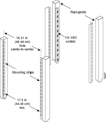
Using Power Strips with a Rack-Mount Installation
Some equipment racks provide a power strip along the length of one of the mounting strips. If your rack has a power strip, consider the position of the strip when planning fastener points to ensure that you can slide cards straight out of their respective slots. If the power strip does impair a rack-mount installation, remove the power strip before installing the chassis in the rack, and then replace it after the chassis is installed. See the “General Rack Installation Guidelines” section for additional information about rack-mounting your system.
Figure 2-2Figure 2-2 shows a typical 19-inch, 4-post equipment rack with a power strip along one of the back posts.
Figure 2-2 Typical 19-Inch Equipment Rack Posts and Mounting Strips
 Feedback