PA-POS-2OC3 Two-Port Packet-over-SONET Port Adapter インストレーション コンフィギュレーション ガイド
偏向のない言語
この製品のマニュアルセットは、偏向のない言語を使用するように配慮されています。このマニュアルセットでの偏向のない言語とは、年齢、障害、性別、人種的アイデンティティ、民族的アイデンティティ、性的指向、社会経済的地位、およびインターセクショナリティに基づく差別を意味しない言語として定義されています。製品ソフトウェアのユーザーインターフェイスにハードコードされている言語、RFP のドキュメントに基づいて使用されている言語、または参照されているサードパーティ製品で使用されている言語によりドキュメントに例外が存在する場合があります。シスコのインクルーシブランゲージに対する取り組みの詳細は、こちらをご覧ください。
翻訳について
このドキュメントは、米国シスコ発行ドキュメントの参考和訳です。リンク情報につきましては、日本語版掲載時点で、英語版にアップデートがあり、リンク先のページが移動/変更されている場合がありますことをご了承ください。あくまでも参考和訳となりますので、正式な内容については米国サイトのドキュメントを参照ください。
- Updated:
- 2012年2月22日
章のタイトル: PA-POS-2OC3 の設定
PA-POS-2OC3 の設定
ポート アダプタのインストレーションを続けるには、Packet-over-SONET(POS)インターフェイスの設定が必要になります。次の手順は、サポート対象の全プラットフォームに適用されます。プラットフォーム別に、Cisco IOS ソフトウェア コマンドのわずかな相違についても説明します。
•![]() 「設定の確認」
「設定の確認」
EXEC コマンド インタープリタの使用方法
ルータのコンフィギュレーションを変更するには、「EXEC(またはイネーブル モード)」と呼ばれるソフトウェア コマンド インタープリタを使用します。 configure コマンドを使用して新規インターフェイスを設定したり、既存のインターフェイス設定を変更したりするには、まず enable コマンドを入力して、EXEC コマンド インタープリタの特権レベルを開始する必要があります。パスワードが設定されている場合には、パスワードの入力が要求されます。
特権レベルのシステム プロンプトは、最後にかぎカッコ(>)ではなくポンド記号(#)が表示されます。コンソール端末で特権レベルを開始する手順は、次のとおりです。
ステップ 1![]() ユーザ レベル EXEC プロンプトで、 enable コマンドを入力します。EXEC プロントでは、特権レベル パスワードの入力が要求されます。
ユーザ レベル EXEC プロンプトで、 enable コマンドを入力します。EXEC プロントでは、特権レベル パスワードの入力が要求されます。
ステップ 2![]() パスワードを入力します(パスワードは大文字と小文字が区別されます)。セキュリティ保護のため、入力したパスワードは表示されません。正しいパスワードを入力すると、特権レベルのシステム プロンプト(#)が表示されます。
パスワードを入力します(パスワードは大文字と小文字が区別されます)。セキュリティ保護のため、入力したパスワードは表示されません。正しいパスワードを入力すると、特権レベルのシステム プロンプト(#)が表示されます。
新規インターフェイスを設定する場合は、「インターフェイスの設定」へ進みます。
インターフェイスの設定
新しい PA-POS-2OC3 が正しく搭載されている(ENABLED LED が点灯する)ことを確認してから、特権レベルの configure コマンドを使用して、新規インターフェイスを設定します。次の情報を用意しておく必要があります。
•![]() IP アドレス(インターフェイスに IP ルーティングを設定する場合)
IP アドレス(インターフェイスに IP ルーティングを設定する場合)
新しい PA-POS-2OC3 を取り付けた場合、または既存インターフェイスの設定を変更する場合には、コンフィギュレーション モードを開始して、新規インターフェイスを設定する必要があります。設定済みの PA-POS-2OC3 を交換した場合には、システムが新規インターフェイスを認識して、既存の設定で各新規インターフェイスを起動します。
使用できるコンフィギュレーション オプションの概要、および PA-POS-2OC3 上のインターフェイスの設定手順については、「関連資料」の該当するコンフィギュレーション マニュアルを参照してください。
EXEC コマンド インタープリタの特権レベルでコンフィギュレーション コマンドを実行するには、通常、パスワードが必要になります。(EXEC 特権レベルについては、EXEC コマンド インタープリタの使用方法を参照)。必要に応じて、システム管理者からパスワードを入手してください。
電源投入時、新しい PA-POS-2OC3 上の OC-3 インターフェイスはシャットダウンされます。インターフェイスをイネーブルにするには、コンフィギュレーション モードで no shutdown コマンドを入力する必要があります(基本的なインターフェイス設定の実行 を参照)。追加引数を指定せずに OC-3 インターフェイスをイネーブルにする(シャットダウン状態から戻す)場合、デフォルトのインターフェイス コンフィギュレーション ファイル パラメータは 表4-1 のとおりです。
|
|
|
|
|---|---|---|
| 1.これらのデフォルト パラメータは、サポート対象の全プラットフォームに搭載の PA-POS-2OC3 に適用されます。 |
基本的なインターフェイス設定の実行
以下に、インターフェイスの有効化( no shutdown コマンドによる)や IP ルーティングの指定など、基本的設定を実行するための手順を示します。システム構成上の要件およびインターフェイスのルーティング プロトコルに応じて、他のコンフィギュレーション コマンドを使用した設定が必要になることがあります。ご使用のポート アダプタのインターフェイスで利用できるコンフィギュレーション コマンドおよびコンフィギュレーション オプションの詳細については、該当するソフトウェア マニュアルを参照してください。
次に示す手順では、特に明記しないかぎり、各ステップの最後に Return キーを押してください。次のようにプロンプトに disable と入力すると、いつでも特権レベルを終了し、ユーザ レベルに戻ることができます。

(注) Cisco 7200 VXR ポート アダプタ ジャケット カードに設定は必要ありません。ポート アダプタ ジャケット カードに搭載されたポート アダプタは、他のポート アダプタと同様に設定します。
ステップ 1![]() コンフィギュレーション モードを開始し、コンフィギュレーション サブコマンドの送信元としてコンソール端末を指定します。
コンフィギュレーション モードを開始し、コンフィギュレーション サブコマンドの送信元としてコンソール端末を指定します。
ステップ 2![]() interface pos サブコマンドのあとに設定対象のインターフェイスのインターフェイス アドレスを入力して、新しく設定するインターフェイスを指定します。
interface pos サブコマンドのあとに設定対象のインターフェイスのインターフェイス アドレスを入力して、新しく設定するインターフェイスを指定します。
表4-2 に、サポートされるプラットフォームでの interface pos サブコマンドの例を示します。
|
|
|
|
|---|---|---|
Cisco 7200 VXR ルータ 2 |
interface pos 、続けて slot/port (ポート アダプタ スロット番号/インターフェイス ポート番号) |
次の例では、ポート アダプタ スロット 6 に搭載した PA-POS-2OC3 のインターフェイス 0 を指定しています。 |
interface pos 、続けて slot/port (ポート アダプタ スロット番号/インターフェイス ポート番号) |
次の例では、ポート アダプタ スロット 1 に搭載した PA-POS-2OC3 のインターフェイス 1 を指定しています。 |
|
interface pos 、続けて slot/port (ポート アダプタ スロット番号/インターフェイス ポート番号) |
次の例では、ポート アダプタ スロット 1 に搭載した PA-POS-2OC3 のインターフェイス 1 を指定しています。 |
|
次の例では、Cisco 7304 ルータのモジュール スロット 3 に搭載した Cisco 7304 PCI ポート アダプタ キャリア カードの PA-POS-2OC3 にインターフェイス 0 を設定しています。 Router(config-if)# |
||
interface pos 、続けて slot/port (ポート アダプタ スロット番号/インターフェイス ポート番号) |
次の例では、ポート アダプタ スロット 1 に搭載した PA-POS-2OC3 のインターフェイス 1 を指定しています。 |
|
interface pos、続けて slot/port adapter/port (インターフェイス プロセッサ スロット番号/ポート アダプタ スロット番号/インターフェイス ポート番号) |
次の例では、インターフェイス プロセッサ スロット 1 に搭載された VIP のポート アダプタ スロット 1 のインターフェイス 0 を指定しています。 |
|
FlexWAN または拡張 FlexWAN モジュール搭載の Cisco 7600 シリーズ ルータ(7603、7606、7609、7613) |
interface pos 、続けて slot/port adapter/port モジュール スロット番号/ポート アダプタ ベイ番号/インターフェイス ポート番号 |
モジュール スロット番号 ― 2 3 ~ 6 または 9(スイッチのスロット数による) |
ステップ 3![]() (IP ルーティングがイネーブルに設定されているシステムでは)次の例のように ip address コンフィギュレーション サブコマンドを入力し、IP アドレスおよびサブネット マスクをインターフェイスに割り当てます。
(IP ルーティングがイネーブルに設定されているシステムでは)次の例のように ip address コンフィギュレーション サブコマンドを入力し、IP アドレスおよびサブネット マスクをインターフェイスに割り当てます。
ステップ 4![]() 次のように、シャットダウン ステートをアップに変更しインターフェイスをイネーブルにします。
次のように、シャットダウン ステートをアップに変更しインターフェイスをイネーブルにします。
no shutdown コマンドは、 enable コマンドをインターフェイスに引き渡し、以前に送信されたコンフィギュレーション コマンドに基づいて Cisco PA-POS-2OC3 ポート アダプタが自動的に設定を行うようにします。
ステップ 5![]() ルーティング プロトコルをイネーブルにするために必要なその他のコンフィギュレーション サブコマンドを追加し、インターフェイス特性を設定します。
ルーティング プロトコルをイネーブルにするために必要なその他のコンフィギュレーション サブコマンドを追加し、インターフェイス特性を設定します。
ステップ 6![]() コンフィギュレーション コマンドをすべて入力して設定を終えたら、 Ctrl-Z を押す( Ctrl キーを押しながら Z を押す)か、 end または exit と入力して、コンフィギュレーション モードを終了し、EXEC コマンド インタープリタ プロンプトに戻ります。
コンフィギュレーション コマンドをすべて入力して設定を終えたら、 Ctrl-Z を押す( Ctrl キーを押しながら Z を押す)か、 end または exit と入力して、コンフィギュレーション モードを終了し、EXEC コマンド インタープリタ プロンプトに戻ります。
ステップ 7![]() 次の手順で、新しいコンフィギュレーションを NVRAM に保管します。
次の手順で、新しいコンフィギュレーションを NVRAM に保管します。
設定のカスタマイズ
ネットワーク環境に合わせて、すべての設定パラメータのデフォルト値をカスタマイズすることができます。PA-POS-2OC3 の設定をカスタマイズする必要がある場合は、以下の各セクションで説明するインターフェイス サブコマンドを実行します。
(注) PA-POS-2OC3 の取り付け先のプラットフォームに関係なく、インターフェイス サブコマンドは同じ働きをします。ただし、どのコマンドを使用する場合でも、最初に interface pos コマンドを入力して、設定するインターフェイスを選択する必要があります。
次に示すすべての設定例において、interface pos コマンドのインターフェイス アドレスの引数は Cisco 7200 VXR ルータの 3/0(ポート アダプタ スロット 3、インターフェイス 0)用です。
特定のプラットフォームで適切な interface pos コマンド構文を使用するには、表4-2を参照してください。
MTU サイズの設定
(注) デフォルト値の 4470 バイトは、自律スイッチング用の Fiber Distributed Data Interface(FDDI)および High-Speed Serial Interface(HSSI)インターフェイスの Maximum Transmission Unit(MTU; 最大伝送ユニット)値と完全に一致します。
ステップ 1![]() MTU サイズを設定する場合は、 mtu bytes コマンドを入力します。ここで bytes は、64 ~ 117994 の範囲の値になります。
MTU サイズを設定する場合は、 mtu bytes コマンドを入力します。ここで bytes は、64 ~ 117994 の範囲の値になります。
ステップ 2![]() デフォルト値の 4470 バイトに戻すには、 no mtu コマンドを入力します。
デフォルト値の 4470 バイトに戻すには、 no mtu コマンドを入力します。
フレーミングの設定
デフォルトのフレーミング値は、SONET STS-3c です。
ステップ 1![]() SDH STM-1 に設定するには、 pos framing sdh コマンドを入力します。
SDH STM-1 に設定するには、 pos framing sdh コマンドを入力します。
ステップ 2![]() SONET STS-3c に戻すには、 no pos framing sdh コマンドを入力します。
SONET STS-3c に戻すには、 no pos framing sdh コマンドを入力します。
送信クロックの送信元の設定
クロッキングのデフォルト値では、PA-POS-2OC3 は復元した受信(RX)クロックを使用して送信(TX)クロッキングを提供するように設定されています(「 ループ タイミング 」と呼ばれる)。
(注) 回線ループバックが選択されると、PA-POS-2OC3 は、ループバックが解除されるまで強制的にループ タイミング モードになります。
ステップ 1![]() Cisco PA-POS-2OC3 ポート アダプタが送信クロックを内部的に生成するように指定する場合は、 clock source internal コマンドを入力します。
Cisco PA-POS-2OC3 ポート アダプタが送信クロックを内部的に生成するように指定する場合は、 clock source internal コマンドを入力します。
ステップ 2![]() ループ タイミングに戻すには、 no clock source internal または clock source line コマンドを入力します。
ループ タイミングに戻すには、 no clock source internal または clock source line コマンドを入力します。
CRC の設定
Cyclic Redundancy Check(CRC; 巡回冗長検査)のデフォルト値は、16 ビット CRC(CRC-CITT)です。CRC は、計算された数値を使用して転送データのエラーを検出するエラー チェック技術です。PA-POS-2OC3 は 32 ビット CRC もサポートしています。データ フレームの送信側で、Frame Check Sequence(FCS)を計算します。送信側は、FCS 値を発信メッセージに付加してからフレームを送信します。受信側では FCS を再計算し、その結果を送信側からの FCS と比較します。2 つの値が異なっていれば、受信側は転送エラーが発生したとみなし、送信側にフレームの再送信を要求します。
ステップ 1![]() 32 ビット CRC にインターフェイスを設定するには、 crc 32 コマンドを入力します。
32 ビット CRC にインターフェイスを設定するには、 crc 32 コマンドを入力します。
ステップ 2![]() 32 ビット CRC をディセーブルにし、デフォルトの 16 ビット CRC 設定にインターフェイスを戻すには、 no crc 32 コマンドを入力します。
32 ビット CRC をディセーブルにし、デフォルトの 16 ビット CRC 設定にインターフェイスを戻すには、 no crc 32 コマンドを入力します。
SONET ペイロード スクランブルの設定
SONET ペイロード スクランブルのデフォルト値はディセーブルです。SONET ペイロード スクランブルは、十分なビット転送密度を保証するため、自己同期スクランブラ(x^43+1)を OC-3 インターフェイスの同期ペイロード エンベロープ(SPE)に適用します。
(注) 接続の両端で、同じスクランブル アルゴリズムを使用する必要があります。
pos scramble-atm コマンドを使用して SONET ペイロード スクランブルをイネーブルにします(このコマンドにはキーワードまたは引数はありません)。
ステップ 1![]() SONET ペイロード スクランブルをイネーブルにするには、次のコマンド シーケンスを使用します。
SONET ペイロード スクランブルをイネーブルにするには、次のコマンド シーケンスを使用します。
ステップ 2![]() SONET ペイロード スクランブルがインターフェイス上でイネーブルになっていることを確認するには、 show startup-config コマンドを入力します。スクランブルがイネーブルになっていると、コンフィギュレーションに次のように表示されます。
SONET ペイロード スクランブルがインターフェイス上でイネーブルになっていることを確認するには、 show startup-config コマンドを入力します。スクランブルがイネーブルになっていると、コンフィギュレーションに次のように表示されます。
pos scramble-atm
ステップ 3![]() SONET ペイロード スクランブルをディセーブルにするには、 no pos scramble-atm コマンドを使用します。
SONET ペイロード スクランブルをディセーブルにするには、 no pos scramble-atm コマンドを使用します。
APS の設定
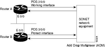
Automatic Protection Switching(APS; 自動保護スイッチング)機能を利用すると、回線障害が起きた場合に、Packet-over-SONET(POS)回線のスイッチオーバーが可能になります。この機能は、SONET 装置を Telco 装置に接続する場合によく使用されます。APS は、現用 POS インターフェイスのバックアップとして、SONET ネットワーク内の保護 POS インターフェイスを使用するメカニズムです。現用インターフェイスに障害が起きると、保護インターフェイスが即座にそのトラフィック伝送を引き継ぎます。
次に、ルータ A とルータ B に APS を設定する例を示します(図4-1を参照)。この例では、ルータ A に現用インターフェイスを、ルータ B に保護インターフェイスを設定します。ルータ A の現用インターフェイスが使用できなくなると、自動的にルータ B の保護インターフェイスに接続が切り替わります。
ルータ A には現用インターフェイスがあります。次の設定を使用します。
interface loopback 1
ip address 10.7.7.7 255.255.255.0
interface pos 2/0/0
aps group 1
pos ais-shut
ルータ B には保護インターフェイスがあります。次の設定を使用します。
pos ais-shut
(注) ループバック インターフェイスは相互接続用です。aps group コマンドを使用して、保護グループを 1 つ設定します。
設定を確認する場合やスイッチオーバーの発生の有無を確認する場合は、show apsコマンドを使用します。
SONET APS の詳細については、次のマニュアルを参照してください。
•![]() 次の URL にある『Automatic Protection Switching of Packet-over-SONET Circuits』
次の URL にある『Automatic Protection Switching of Packet-over-SONET Circuits』
http://www.cisco.com/en/US/products/sw/iosswrel/ps1824/products_feature_guide09186a0080087ad9.html
•![]() 次の URL にある『 Configuring Redundancy for POS/APS 』
次の URL にある『 Configuring Redundancy for POS/APS 』
http://www.cisco.com/en/US/tech/tk482/tk607/technologies_tech_note09186a0080094c54.shtml
設定の確認
新規インターフェイスを設定したあとで、 show コマンドを使用して新規インターフェイスまたは全インターフェイスのステータスを表示し、ping コマンドおよび loopback コマンドを使用して接続を確認します。ここでは次の項目について説明します。
•![]() 「show コマンドによる新規インターフェイスのステータス確認」
「show コマンドによる新規インターフェイスのステータス確認」
コマンドの詳細および使用例については、「関連資料」に記載されているマニュアルを参照してください。
show コマンドによる新規インターフェイスのステータス確認
表4-3 に、 show コマンドを使用して、新規インターフェイスが正しく設定されて正常に動作しているかどうかと、PA-POS-2OC3 が正しく表示されているかどうかを確認する方法を示します。次に、一部の show コマンドについて出力例を紹介します。
(注) このマニュアルで紹介する出力例は、実際にコマンドを実行した場合に得られる出力とは異なる場合があります。このマニュアルに収録されている出力は、あくまでも例です。
アップに設定したインターフェイスがシャットダウンされている場合、またはハードウェアが正しく動作していないというメッセージが表示された場合には、インターフェイスが正しく接続され、終端されているかどうかを確認してください。それでも、インターフェイスをアップに設定できないときは、製品を購入した代理店に連絡してください。ここでは次の項目について説明します。
•![]() 「show version または show hardware コマンドの使用例」
「show version または show hardware コマンドの使用例」
使用システムに当てはまる項目を選択してください。 show コマンドを使用した作業が終了したら、「ping コマンドによるネットワーク接続の確認」に進んでください。
show version または show hardware コマンドの使用例
システムのハードウェア構成、タイプ別の搭載インターフェイス数、Cisco IOS ソフトウェアのバージョン、コンフィギュレーション ファイルの名前とソース、およびブート イメージを表示するには、 show version (または show hardware )コマンドを使用します。ここでは一部のサポート対象プラットフォームでの例を示します。
(注) このマニュアルで紹介する出力例は、実際にコマンドを実行した場合に得られる出力とは異なる場合があります。このマニュアルに収録されている出力は、あくまでも例です。
以下のセクションでは、 show version コマンドを実行した場合の各プラットフォームの出力例を示します。
•![]() 「Cisco 7200 VXR ルータ ― show version コマンドの出力例」
「Cisco 7200 VXR ルータ ― show version コマンドの出力例」
•![]() 「Cisco 7201 ルータ ― show version コマンドの出力例」
「Cisco 7201 ルータ ― show version コマンドの出力例」
•![]() 「Cisco 7301 ルータ ― show version コマンドの出力例」
「Cisco 7301 ルータ ― show version コマンドの出力例」
•![]() 「Cisco 7304 ルータ ― show version コマンドの出力例」
「Cisco 7304 ルータ ― show version コマンドの出力例」
•![]() 「Cisco 7401 ASR ルータ ― show version コマンドの出力例」
「Cisco 7401 ASR ルータ ― show version コマンドの出力例」
•![]() 「Cisco 7500 シリーズ ルータの VIP ― show version コマンドの出力例」
「Cisco 7500 シリーズ ルータの VIP ― show version コマンドの出力例」
•![]() 「FlexWAN および拡張 FlexWAN モジュール搭載の Cisco 7600 ルータ ― show version コマンドの出力例」
「FlexWAN および拡張 FlexWAN モジュール搭載の Cisco 7600 ルータ ― show version コマンドの出力例」
Cisco 7200 VXR ルータ ― show version コマンドの出力例
次に、PA-POS-2OC3 を搭載した Cisco 7206 VXR シリーズ ルータの show version コマンドの出力例を示します。
Cisco 7201 ルータ ― show version コマンドの出力例
次に、Cisco 7201 ルータの show version コマンドの出力例を示します。
Cisco 7301 ルータ ― show version コマンドの出力例
次に、Cisco PA-POS-2OC3 ポート アダプタを搭載した Cisco 7301 ルータの show version コマンドの出力例を示します。
IOS (tm) 7301 Software (C7301-JS-M), Version 12.3(9), RELEASE SOFTWARE (fc2)
Copyright (c) 1986-2004 by cisco Systems, Inc.
Compiled Fri 14-May-04 09:42 by dchih
Image text-base: 0x60008AF4, data-base: 0x61F86000
System returned to ROM by power-on
System image file is "disk0:c7301-js-mz.123-9"
Processor board ID 74804277
SB-1 CPU at 700MHz, Implementation 1, Rev 0.2, 512KB L2 Cache
1 slot midplane, Version 2.0
Bridging software.
X.25 software, Version 3.0.0.
SuperLAT software (copyright 1990 by Meridian Technology Corp).
TN3270 Emulation software.
3 Gigabit Ethernet/IEEE 802.3 interface(s)
2 Packet over SONET network interface(s)
509K bytes of non-volatile configuration memory.
32768K bytes of Flash internal SIMM (Sector size 256K).
Configuration register is 0x2102
Cisco 7304 ルータ ― show version コマンドの出力例
次に、Cisco PA-POS-2OC3 ポート アダプタを搭載した Cisco 7304 ルータの show version コマンドの出力例を示します。
Cisco 7401 ASR ルータ ― show version コマンドの出力例
次に、Cisco PA-POS-2OC3 ポート アダプタを搭載した Cisco 7401 ASR ルータの show version コマンドの出力例を示します。
Cisco 7500 シリーズ ルータの VIP ― show version コマンドの出力例
次に、Cisco PA-POS-2OC3 ポート アダプタを搭載した Cisco 7500 シリーズ ルータの show version コマンドの出力例を示します。
FlexWAN および拡張 FlexWAN モジュール搭載の Cisco 7600 ルータ ― show version コマンドの出力例
次に、Flex WAN モジュールに Cisco PA-POS-2OC3 ポート アダプタを搭載した Cisco 7600 ルータの show version コマンドの出力例を示します。
show diag コマンドの使用例
show diag slot コマンドを使用すると、システムに搭載されているポート アダプタのタイプ(および各アダプタの情報)が表示されます。このコマンドの slot は、Cisco 7200 VXR シリーズ ルータ、Cisco 7201 ルータ、Cisco 7301 ルータ、および Cisco 7401 ASR ルータでは ポート アダプタ スロット を、Cisco 7304 ルータに搭載した Cisco 7304 PCI ポート アダプタ キャリア カードでは モジュール スロット を、VIP 搭載の Cisco 7500 シリーズ ルータでは インターフェイス プロセッサ スロット を表します。FlexWAN モジュールの場合、show diag コマンドは slot を指定せずに実行します。
(注) このマニュアルで紹介する出力例は、実際にコマンドを実行した場合に得られる出力とは異なる場合があります。このマニュアルに収録されている出力は、あくまでも例です。
以下の各セクションでは、 show diag コマンドを実行した場合の各プラットフォームの出力例を示します。
•![]() 「Cisco 7200 VXR シリーズ ルータ ― show diag コマンドの出力例」
「Cisco 7200 VXR シリーズ ルータ ― show diag コマンドの出力例」
•![]() 「Cisco 7201 ルータ ― show diag コマンドの出力例」
「Cisco 7201 ルータ ― show diag コマンドの出力例」
•![]() 「Cisco 7301 ルータ ― show diag コマンドの出力例」
「Cisco 7301 ルータ ― show diag コマンドの出力例」
•![]() 「Cisco 7304 ルータ ― show diag コマンドの出力例」
「Cisco 7304 ルータ ― show diag コマンドの出力例」
•![]() 「Cisco 7401 ASR ルータ ― show diag コマンドの出力例」
「Cisco 7401 ASR ルータ ― show diag コマンドの出力例」
•![]() 「Cisco 7500 シリーズ ルータの VIP ― show diag コマンドの出力例」
「Cisco 7500 シリーズ ルータの VIP ― show diag コマンドの出力例」
•![]() 「FlexWAN および拡張 FlexWAN モジュール搭載の Cisco 7600 シリーズ ルータ ― show diag コマンドの出力例」
「FlexWAN および拡張 FlexWAN モジュール搭載の Cisco 7600 シリーズ ルータ ― show diag コマンドの出力例」
Cisco 7200 VXR シリーズ ルータ ― show diag コマンドの出力例
次に、Cisco 7200 VXR ルータのポート アダプタ スロット 2 に搭載された PA-POS-2OC3 に対する show diag コマンドの出力例を示します。
Cisco 7201 ルータ ― show diag コマンドの出力例
次に、Cisco 7201 ルータの show diag コマンドの出力例を示します。
Cisco 7301 ルータ ― show diag コマンドの出力例
次に、Cisco 7301 ルータのポート アダプタ スロット 1 に搭載された PA-POS-2OC3 に対する show diag コマンドの出力例を示します。
Port adapter is analyzed
Port adapter insertion time 7w2d ago
EEPROM contents at hardware discovery:
Hardware Revision : 1.0
PCB Serial Number : JAE080216FB
Part Number : 73-8220-02
Board Revision : A0
RMA Test History : 00
RMA Number : 0-0-0-0
RMA History : 00
Deviation Number : 0
Product (FRU) Number : PA-POS-2OC3
Top Assy. Part Number : 800-21857-02
EEPROM format version 4
EEPROM contents (hex):
0x10: 32 31 36 46 42 82 49 20 1C 02 42 41 30 03 00 81
0x20: 00 00 00 00 04 00 88 00 00 00 00 CB 94 50 41 2D
0x30: 50 4F 53 2D 32 4F 43 33 20 20 20 20 20 20 20 20
0x40: 20 C0 46 03 20 00 55 61 02 FF FF FF FF FF FF FF
0x50: FF FF FF FF FF FF FF FF FF FF FF FF FF FF FF FF
0x60: FF FF FF FF FF FF FF FF FF FF FF FF FF FF FF FF
0x70: FF FF FF FF FF FF FF FF FF FF FF FF FF FF FF FF
Cisco 7304 ルータ ― show diag コマンドの出力例
次に、Cisco 7304 ルータのルータ モジュール スロット 5 に搭載された PA-POS-2OC3 に対する show diag コマンドの出力例を示します。
Cisco 7401 ASR ルータ ― show diag コマンドの出力例
次に、Cisco 7401 ASR ルータのポート アダプタ スロット 1 に搭載された PA-POS-2OC3 に対する show diag コマンドの出力例を示します。
Cisco 7500 シリーズ ルータの VIP ― show diag コマンドの出力例
次に、インターフェイス プロセッサ スロット 1 に装着された VIP のポート アダプタ スロット 4 に搭載された PA-POS-2OC3 に対する show diag コマンドの出力例を示します。
FlexWAN および拡張 FlexWAN モジュール搭載の Cisco 7600 シリーズ ルータ ― show diag コマンドの出力例
次に、Flex WAN モジュールのベイ 1 に搭載された PA-POS-2OC3 に対する show diag コマンドの出力例を示します。
show interfaces コマンドの使用例
show interfaces コマンドを使用すると、指定したインターフェイスのステータス情報(物理スロットおよびインターフェイス アドレスを含む)が表示されます。
個別のプラットフォームで使用できるインターフェイス サブコマンドおよびコンフィギュレーション オプションの詳細については、「関連資料」に記載されているマニュアルを参照してください。
(注) このマニュアルで紹介する出力例は、実際にコマンドを実行した場合に得られる出力とは異なる場合があります。このマニュアルに収録されている出力は、あくまでも例です。
以下の各セクションでは、 show interfaces コマンドを実行した場合の各プラットフォームの出力例を示します。
•![]() 「Cisco 7200 VXR ルータ ― show interfaces コマンドの出力例」
「Cisco 7200 VXR ルータ ― show interfaces コマンドの出力例」
•![]() 「Cisco 7201 ルータ ― show interfaces コマンドの出力例」
「Cisco 7201 ルータ ― show interfaces コマンドの出力例」
•![]() 「Cisco 7301 ルータ ― show interfaces コマンドの出力例」
「Cisco 7301 ルータ ― show interfaces コマンドの出力例」
•![]() 「Cisco 7304 ルータ ― show interfaces コマンドの出力例」
「Cisco 7304 ルータ ― show interfaces コマンドの出力例」
•![]() 「Cisco 7401 ASR ルータ ― show interfaces コマンドの出力例」
「Cisco 7401 ASR ルータ ― show interfaces コマンドの出力例」
•![]() 「Cisco 7500 シリーズ ルータの VIP ― show interfaces コマンドの出力例」
「Cisco 7500 シリーズ ルータの VIP ― show interfaces コマンドの出力例」
•![]() 「FlexWAN および拡張 FlexWAN モジュール搭載の Cisco 7600 シリーズ ルータ ― show interfaces コマンドの出力例」
「FlexWAN および拡張 FlexWAN モジュール搭載の Cisco 7600 シリーズ ルータ ― show interfaces コマンドの出力例」
Cisco 7200 VXR ルータ ― show interfaces コマンドの出力例
次に、Cisco 7200 VXR ルータのポート アダプタ スロット 4 に搭載された PA-POS-2OC3 に対する show interfaces pos コマンドの出力例を示します。
(注) Cisco AS5800 ユニバーサル アクセス ルータ内の Cisco 7206 VXR ルータ シェルフの場合は、show interfaces pos コマンドにシェルフ番号を指定する必要があります。指定形式は、show interfaces pos シェルフ番号/ポート アダプタ スロット番号/インターフェイス ポートになります(たとえば、show interfaces pos 5/3/0 コマンドは、ルータ シェルフ 5 のポート アダプタ スロット 3 に搭載された Cisco PA-POS-2OC3 ポート アダプタの OC-3 インターフェイスを指定)。
Cisco 7201 ルータ ― show interfaces コマンドの出力例
次に、Cisco 7201 ルータの show interfaces コマンドの出力例を示します。
Cisco 7301 ルータ ― show interfaces コマンドの出力例
次に、Cisco 7301 ルータに搭載された PA-POS-2OC3 に対する show interfaces コマンドの出力例を示します。
Internet address is 198.1.1.1/24
MTU 1500 bytes, BW 1000000 Kbit, DLY 10 usec,
reliability 255/255, txload 1/255, rxload 1/255
Encapsulation ARPA, loopback not set
Keepalive not set
Full-duplex, 1000Mb/s, media type is RJ45
output flow-control is XON, input flow-control is XON
ARP type: ARPA, ARP Timeout 04:00:00
Last input never, output 00:05:28, output hang never
Last clearing of "show interface" counters never
Input queue: 0/75/0/0 (size/max/drops/flushes); Total output drops: 0
Queueing strategy: fifo
Output queue: 0/40 (size/max)
30 second input rate 0 bits/sec, 0 packets/sec
30 second output rate 0 bits/sec, 0 packets/sec
0 packets input, 0 bytes, 0 no buffer
Received 0 broadcasts, 0 runts, 0 giants, 0 throttles
0 input errors, 0 CRC, 0 frame, 0 overrun, 0 ignored
0 watchdog, 0 multicast, 0 pause input
0 input packets with dribble condition detected
7349 packets output, 565794 bytes, 0 underruns
3 output errors, 0 collisions, 4 interface resets
0 babbles, 0 late collision, 0 deferred
3 lost carrier, 0 no carrier, 0 pause output
0 output buffer failures, 0 output buffers swapped out
GigabitEthernet0/1 is up, line protocol is up
Internet address is 200.1.1.1/24
MTU 1500 bytes, BW 1000000 Kbit, DLY 10 usec,
reliability 255/255, txload 1/255, rxload 1/255
Encapsulation ARPA, loopback not set
Keepalive not set
Full-duplex, 1000Mb/s, link type is autonegotiation, media type is SX
output flow-control is XON, input flow-control is XON
ARP type: ARPA, ARP Timeout 04:00:00
Last input 00:50:13, output 00:05:30, output hang never
Last clearing of "show interface" counters never
Input queue: 0/75/0/0 (size/max/drops/flushes); Total output drops: 0
Queueing strategy: fifo
Output queue: 0/40 (size/max)
30 second input rate 0 bits/sec, 0 packets/sec
30 second output rate 0 bits/sec, 0 packets/sec
353 packets input, 31060 bytes, 0 no buffer
Received 0 broadcasts, 0 runts, 0 giants, 0 throttles
0 input errors, 0 CRC, 0 frame, 0 overrun, 0 ignored
0 watchdog, 23988 multicast, 0 pause input
0 input packets with dribble condition detected
7757 packets output, 591048 bytes, 0 underruns
3 output errors, 0 collisions, 4 interface resets
0 babbles, 0 late collision, 0 deferred
3 lost carrier, 0 no carrier, 0 pause output
0 output buffer failures, 0 output buffers swapped out
GigabitEthernet0/2 is up, line protocol is up
MTU 1500 bytes, BW 100000 Kbit, DLY 100 usec,
reliability 255/255, txload 1/255, rxload 1/255
Encapsulation ARPA, loopback not set
Keepalive set (10 sec)
Full-duplex, 100Mb/s, media type is RJ45
output flow-control is XON, input flow-control is XON
ARP type: ARPA, ARP Timeout 04:00:00
Last input 00:00:14, output 00:00:03, output hang never
Last clearing of "show interface" counters never
Input queue: 0/75/0/0 (size/max/drops/flushes); Total output drops: 0
Queueing strategy: fifo
Output queue: 0/40 (size/max)
5 minute input rate 0 bits/sec, 0 packets/sec
5 minute output rate 0 bits/sec, 0 packets/sec
251458 packets input, 38023771 bytes, 0 no buffer
Received 0 broadcasts, 0 runts, 0 giants, 0 throttles
0 input errors, 0 CRC, 0 frame, 0 overrun, 0 ignored
0 watchdog, 797565 multicast, 0 pause input
0 input packets with dribble condition detected
523031 packets output, 51462809 bytes, 0 underruns
8 output errors, 0 collisions, 4 interface resets
0 babbles, 0 late collision, 0 deferred
8 lost carrier, 0 no carrier, 0 pause output
0 output buffer failures, 0 output buffers swapped out
POS1/0 is administratively down, line protocol is down
reliability 255/255, txload 1/255, rxload 1/255
Encapsulation HDLC, crc 16, loopback not set
Keepalive set (10 sec)
Scramble disabled
Last input never, output never, output hang never
Last clearing of "show interface" counters never
Input queue: 0/75/0/0 (size/max/drops/flushes); Total output drops: 0
Queueing strategy: fifo
Output queue: 0/40 (size/max)
5 minute input rate 0 bits/sec, 0 packets/sec
5 minute output rate 0 bits/sec, 0 packets/sec
0 packets input, 0 bytes, 0 no buffer
Received 0 broadcasts, 0 runts, 0 giants, 0 throttles
0 parity
0 input errors, 0 CRC, 0 frame, 0 overrun, 0 ignored, 0 abort
0 packets output, 0 bytes, 0 underruns
0 output errors, 0 applique, 0 interface resets
0 output buffer failures, 0 output buffers swapped out
0 carrier transitions
POS1/1 is administratively down, line protocol is down
reliability 255/255, txload 1/255, rxload 1/255
Encapsulation HDLC, crc 16, loopback not set
Keepalive set (10 sec)
Scramble disabled
Last input never, output never, output hang never
Last clearing of "show interface" counters never
Input queue: 0/75/0/0 (size/max/drops/flushes); Total output drops: 0
Queueing strategy: fifo
Output queue: 0/40 (size/max)
5 minute input rate 0 bits/sec, 0 packets/sec
5 minute output rate 0 bits/sec, 0 packets/sec
0 packets input, 0 bytes, 0 no buffer
Received 0 broadcasts, 0 runts, 0 giants, 0 throttles
0 parity
0 input errors, 0 CRC, 0 frame, 0 overrun, 0 ignored, 0 abort
0 packets output, 0 bytes, 0 underruns
0 output errors, 0 applique, 0 interface resets
0 output buffer failures, 0 output buffers swapped out
0 carrier transitions
Cisco 7304 ルータ ― show interfaces コマンドの出力例
次に、Cisco 7304 ルータのポート アダプタ スロット 5 に搭載された PA-POS-2OC3 に対する show interfaces pos コマンドの出力例を示します。
Cisco 7401 ASR ルータ ― show interfaces コマンドの出力例
次に、Cisco 7401 ASR ルータのポート アダプタ スロット 1 に搭載された PA-POS-2OC3 に対する show interfaces pos コマンドの出力例を示します。
Cisco 7500 シリーズ ルータの VIP ― show interfaces コマンドの出力例
次に、VIP で使用する show interfaces pos コマンドの出力例を示します。この例では、2 つのシリアル インターフェイス(0 または 1)が、インターフェイス プロセッサ スロット 1 に搭載された VIP のポート アダプタ スロット 1 に取り付けられたポート アダプタ上にあることを示しています。各インターフェイスのステータス情報の大半は省略しています(インターフェイスをイネーブルにするまで、インターフェイスは管理上のシャットダウンになっています)。
FlexWAN および拡張 FlexWAN モジュール搭載の Cisco 7600 シリーズ ルータ ― show interfaces コマンドの出力例
次に、Cisco 7609 ルータ(スロット 8)の Flex WAN モジュールのスロット 1 に搭載された PA-POS-2OC3 に対する show interfaces pos コマンドの出力例を示します。
ping コマンドによるネットワーク接続の確認
ping コマンドを使用することにより、インターフェイス ポートが正常に動作しているかどうかを確認できます。ここでは、ping コマンドの概要を説明します。コマンドの詳細および使用例については、「関連資料」に記載されているマニュアルを参照してください。
ping コマンドは、指定した IP アドレスのリモート デバイスに対してエコー要求パケットを送信します。エコー要求の送信後、システムは指定された時間だけ、リモート デバイスからの応答を待機します。エコー応答は、コンソール端末に感嘆符(!)で表示されます。タイムアウトまでに応答がなかった各要求は、ピリオド(.)で表示されます。連続する感嘆符(!!!!!)は正常な接続状態を示します。連続するピリオド(.....)、(timed out)、または(failed)メッセージが表示された場合は、接続に失敗したことを意味します。
次に、アドレス 10.0.0.10 のリモート サーバに対して ping コマンドを実行し、正常に接続した例を示します。
接続に失敗した場合は、宛先の IP アドレスが正しいこと、およびデバイスがアクティブである(電源がオンになっている)ことを確認し、再度 ping コマンドを実行してください。
loopback コマンドの使用例
ループバック テストでOC-3 インターフェイスとリモート デバイス間の接続をテストすることにより、機器の誤動作の検出、特定、およびトラブルシューティングを行うことができます。 loopback コマンドで、インターフェイスを内部ループバック(「 ローカル ループバック 」とも呼ばれる)モードまたは回線ループバック モードにすると、 ping コマンドで生成されたテスト パケットがリモート デバイスまたはケーブルを経由してループされます。パケットがループを完了した場合は、接続が良好です。完全なループにならなかった場合は、ループバック テスト パス上のリモート デバイスまたはケーブルに障害があることが特定できます。
(注) 回線ループバックになると、インターフェイスは自動的にループ タイミングに切り替わります。一度ループバックが解除されれば、インターフェイスはユーザ指定のタイミング ソースに戻ります。
内部ループバック用のインターフェイスの設定
デフォルトのループバック設定は、no loopback です。内部(またはローカル)ループバックの場合、ルータからのパケットはフレーマー内でループバックされます。発信データは、実際に伝送されずにレシーバーに戻ってきます。内部ループバックは、PA-POS-2OC3 が動作しているかどうかを確認するのに役立ちます。
ステップ 1![]() 内部ループバック用のインターフェイスを設定するには、 loop internal コマンドを入力します。
内部ループバック用のインターフェイスを設定するには、 loop internal コマンドを入力します。
ステップ 2![]() 内部ループバックをディセーブルにするには、 no loop internal コマンドを入力します。
内部ループバックをディセーブルにするには、 no loop internal コマンドを入力します。
回線ループバック用のインターフェイスの設定
(注) 回線ループバックになると、インターフェイスは自動的にループ タイミングに切り替わります。ループバックが解除されれば、インターフェイスはユーザ指定のタイミング ソースに戻ります。
デフォルトのループバック設定は、no loopback です。回線ループバックの場合、リモート ルータからのパケットがリモート ルータに戻るように受信(RX)ファイバが送信(TX)光ファイバ ケーブルに論理的に接続されます。着信データはループされ、リモート エンドに送信されて、無意味な受信部分を省略します。
ステップ 1![]() 回線ループバック用のインターフェイスを設定するには、 loop line コマンドを入力します。
回線ループバック用のインターフェイスを設定するには、 loop line コマンドを入力します。
ステップ 2![]() 回線ループバックをディセーブルにするには、 no loop line コマンドを入力します。
回線ループバックをディセーブルにするには、 no loop line コマンドを入力します。
個別のプラットフォームで使用できるインターフェイス サブコマンドおよびコンフィギュレーション オプションの詳細については、「関連資料」に記載されているマニュアルを参照してください。
プッシュ モードの概要
ここで示す情報は、シスコから指示を受けた場合以外には使用しないでください。
PA-POS-2OC3 および PA-POS-1OC3 ポート アダプタでは、データ処理の際に独自のアルゴリズム(一般的なポート アダプタと比較した場合)を使用します。送信側では、CPU からパケットをプルする(プル モード)か、または CPU からポート アダプタにパケットをプッシュする(プッシュ モード)かを選択できます。PA-POS-2OC3 および PA-POS-1OC3 のポート アダプタは、以前に開発されたポート アダプタの設計とは異なるソフトウェア アーキテクチャに基づいて開発されました。大部分のポート アダプタでは、CPU から対応する各インターフェイスへとデータをプルすることができます。ごくまれなケースではありますが、PA-POS-2OC3 および PA-POS-1OC3 ポート アダプタを他のポート アダプタ製品ファミリと同様に動作させるために、設定が必要になる可能性があります。ここで説明する新しい CLI を利用することで、PA-POS-2OC3 および PA-POS-1OC3 ポート アダプタのプッシュ モード動作を、標準的なプル モードに変更することができます。

(注) プッシュ モードからプル モードへの変更は、NPE-G1 および PA-POS-2OC3 または PA-POS-1OC3 を搭載した Cisco 7200 VXR ルータだけに適用できます。
(注) モード変更は、標準的なメンテナンス ウインドウの間に実施することを推奨します。
プル モードは Cisco IOS Release 12.4(15)T1 でサポートされます。
TX DMA モードをデフォルトのプッシュ モードからプル モードへ変更する手順は、次のとおりです。
•![]() プッシュ モードをプル モードに変更するには、dma model pull enable コマンドを使用します。dma model pull enable コマンドを実行すると、搭載済みのすべての PA-POS-1OC3 および PA-POS-2OC3 ポート アダプタでソフト活性挿抜が有効になり、再初期化が実行されてプル モードになります。
プッシュ モードをプル モードに変更するには、dma model pull enable コマンドを使用します。dma model pull enable コマンドを実行すると、搭載済みのすべての PA-POS-1OC3 および PA-POS-2OC3 ポート アダプタでソフト活性挿抜が有効になり、再初期化が実行されてプル モードになります。
•![]() プル モードをプッシュ モードに変更するには、no dma model pull enable コマンドを実行します。no dma model pull enable コマンドを実行すると、すべての PA-POS ポート アダプタでソフト活性挿抜が有効になり、再初期化が実行されてプッシュ モードになります。
プル モードをプッシュ モードに変更するには、no dma model pull enable コマンドを実行します。no dma model pull enable コマンドを実行すると、すべての PA-POS ポート アダプタでソフト活性挿抜が有効になり、再初期化が実行されてプッシュ モードになります。
PA-POS-2OC3 統計カウンタ
PA-POS-2OC3 では、特定のエラー数がカウントされています。各エラー カウンタは 16 ビットです。エラーには次のような種類があります。
•![]() ジャイアント パケットの受信 ― パケット サイズが大きすぎる(16 KB を超える)
ジャイアント パケットの受信 ― パケット サイズが大きすぎる(16 KB を超える)
PA-POS-2OC3 エラー メッセージ
出力される唯一のエラー メッセージは、次のフォーマットで表示されます。
(注) このエラー メッセージに関してサポートが必要な場合は、Cisco Technical Assistance Center(TAC)にご連絡ください。
バックツーバック接続の確立
ここでは、OC-3 インターフェイスを通じてバックツーバック接続されている Cisco 7200 VXR ルータおよび Cisco 7401 ASR ルータのコンフィギュレーション ファイル例を 2 つ示します。
ステップ 1![]() PA-POS-2OC3 を装備した 2 台のルータをバックツーバック接続するには、各 PA-POS-2OC3 上の OC-3 インターフェイス ポートを適切なケーブルで接続します。
PA-POS-2OC3 を装備した 2 台のルータをバックツーバック接続するには、各 PA-POS-2OC3 上の OC-3 インターフェイス ポートを適切なケーブルで接続します。
デフォルト設定により、PA-POS-2OC3 はループ タイミング モードを使用します。
ステップ 2![]() Cisco PA-POS-2OC3 ポート アダプタが送信クロックを内部的に生成することを指定するには、コンフィギュレーションに clock source internal コマンドを追加します(下記の最初のルータの例を参照: clock source internal )。
Cisco PA-POS-2OC3 ポート アダプタが送信クロックを内部的に生成することを指定するには、コンフィギュレーションに clock source internal コマンドを追加します(下記の最初のルータの例を参照: clock source internal )。
(注) バックツーバック接続の場合、少なくとも 1 つの接続された OC-3 インターフェイスで、内部クロックを回線に供給するように設定する必要があります。
 フィードバック