-
null
Bias-Free Language
The documentation set for this product strives to use bias-free language. For the purposes of this documentation set, bias-free is defined as language that does not imply discrimination based on age, disability, gender, racial identity, ethnic identity, sexual orientation, socioeconomic status, and intersectionality. Exceptions may be present in the documentation due to language that is hardcoded in the user interfaces of the product software, language used based on RFP documentation, or language that is used by a referenced third-party product. Learn more about how Cisco is using Inclusive Language.
- Updated:
- March 17, 2015
Chapter: Configuring Mobility Groups
Configuring Mobility Groups
This chapter describes mobility groups and explains how to configure them on WCS. It contains these sections:
•![]() Configuring Multiple Country Codes
Configuring Multiple Country Codes
Overview of Mobility
Mobility, or roaming, is a wireless LAN client's ability to maintain its association seamlessly from one access point to another securely and with as little latency as possible. This section explains how mobility works when controllers are included in a wireless network.
When a wireless client associates and authenticates to an access point, the access point's controller places an entry for that client in its client database. This entry includes the client's MAC and IP addresses, security context and associations, quality of service (QoS) contexts, the WLAN, and the associated access point. The controller uses this information to forward frames and manage traffic to and from the wireless client. Figure 8-1 illustrates a wireless client roaming from one access point to another when both access points are joined to the same controller.
Figure 8-1 Intra-Controller Roaming
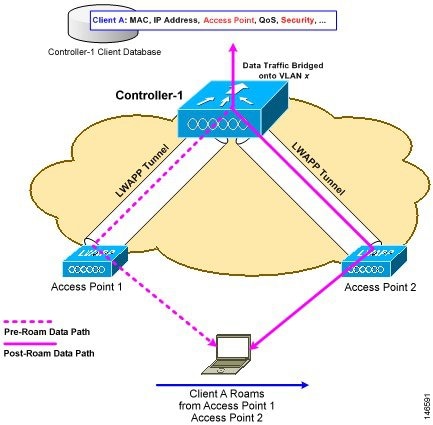
When the wireless client moves its association from one access point to another, the controller simply updates the client database with the newly associated access point. If necessary, new security context and associations are established as well.
The process becomes more complicated, however, when a client roams from an access point joined to one controller to an access point joined to a different controller. The process also varies based on whether the controllers are operating on the same subnet. Figure 8-2 illustrates inter-controller roaming, which occurs when the controllers' wireless LAN interfaces are on the same IP subnet.
Figure 8-2 Inter-Controller Roaming
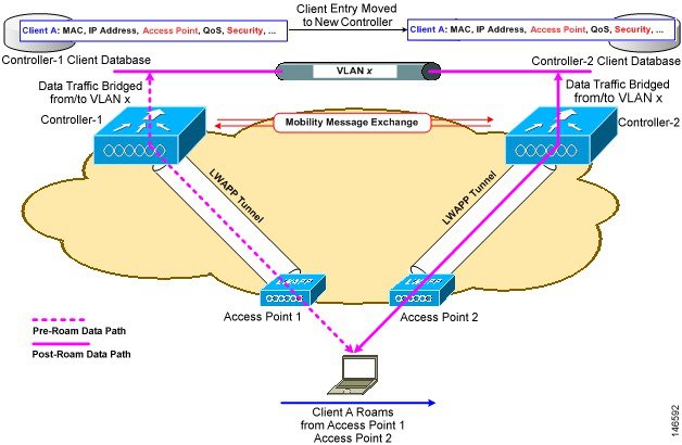
When the client associates to an access point joined to a new controller, the new controller exchanges mobility messages with the original controller, and the client database entry is moved to the new controller. New security context and associations are established if necessary, and the client database entry is updated for the new access point. This process remains invisible to the user.

Note ![]() All clients configured with 802.1X/Wi-Fi Protected Access (WPA) security complete a full authentication in order to comply with the IEEE standard.
All clients configured with 802.1X/Wi-Fi Protected Access (WPA) security complete a full authentication in order to comply with the IEEE standard.
Figure 8-3 illustrates inter-subnet roaming, which occurs when the controllers' wireless LAN interfaces are on different IP subnets.
Figure 8-3 Inter-Subnet Roaming
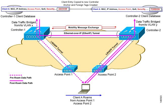
Inter-subnet roaming is similar to inter-controller roaming in that the controllers exchange mobility messages on how the client roams. However, instead of moving the client database entry to the new controller, the original controller marks the client with an "Anchor" entry in its own client database. The database entry is copied to the new controller client database and marked with a "Foreign" entry in the new controller. The roam remains invisible to the wireless client, and the client maintains its original IP address.
After an inter-subnet roam, data flows in an asymmetric traffic path to and from the wireless client. Traffic from the client to the network is forwarded directly into the network by the foreign controller. Traffic to the client arrives at the anchor controller, which forwards the traffic to the foreign controller in an EtherIP tunnel. The foreign controller then forwards the data to the client. If a wireless client roams to a new foreign controller, the client database entry is moved from the original foreign controller to the new foreign controller, but the original anchor controller is always maintained. If the client moves back to the original controller, it becomes local again.
In inter-subnet roaming, WLANs on both anchor and foreign controllers need to have the same network access privileges and no source-based routing or source-based firewalls in place. Otherwise, the clients may have network connectivity problems after the handoff.
Note ![]() Currently, multicast traffic cannot be passed during inter-subnet roaming. In other words, avoid designing an inter-subnet network for Spectralink phones that need to send multicast traffic while using push to talk.
Currently, multicast traffic cannot be passed during inter-subnet roaming. In other words, avoid designing an inter-subnet network for Spectralink phones that need to send multicast traffic while using push to talk.
Note ![]() Both inter-controller roaming and inter-subnet roaming require the controllers to be in the same mobility group. See the next two sections for a description of mobility groups and instructions for configuring them.
Both inter-controller roaming and inter-subnet roaming require the controllers to be in the same mobility group. See the next two sections for a description of mobility groups and instructions for configuring them.
Symmetric Tunneling
With symmetric mobility tunneling, the controller provides inter-subnet mobility for clients roaming from one access point to another within a wireless LAN. The client traffic on the wired network is directly routed by the foreign controller. If a router has reverse path filtering (RPF) enabled (which provides additional checks on incoming packets), the communication is blocked. Symmetric mobility tunneling allows the client traffic to reach the controller designated as the anchor, even with RPF enabled. You enable or disable symmetric tunneling by choosing Configure > Controller and then System > General from the left sidebar menu.
Note ![]() All controllers in a mobility group should have the same symmetric tunneling mode.
All controllers in a mobility group should have the same symmetric tunneling mode.
Note ![]() For symmetric tunneling to take effect, a reboot is required.
For symmetric tunneling to take effect, a reboot is required.
With this guest tunneling N+1 redundancy feature, the time it takes for a client to join another access point following a controller failure is decreased because a failure is quickly identified, the clients are moved away from the problem controller, and the clients are anchored to another controller.
Refer to the "Configuring General Templates" section on page 10-4 for instructions on configuring this feature within a template.
Overview of Mobility Groups
A set of controllers can be configured as a mobility group to allow seamless client roaming within a group of controllers. By creating a mobility group, you can enable multiple controllers in a network to dynamically share information and forward data traffic when inter-controller or inter-subnet roaming occurs. Controllers can share the context and state of client devices and controller loading information. With this information, the network can support inter-controller wireless LAN roaming and controller redundancy.
Note ![]() Clients do not roam across mobility groups.
Clients do not roam across mobility groups.
Figure 8-4 shows an example of a mobility group.
Figure 8-4 A Single Mobility Group
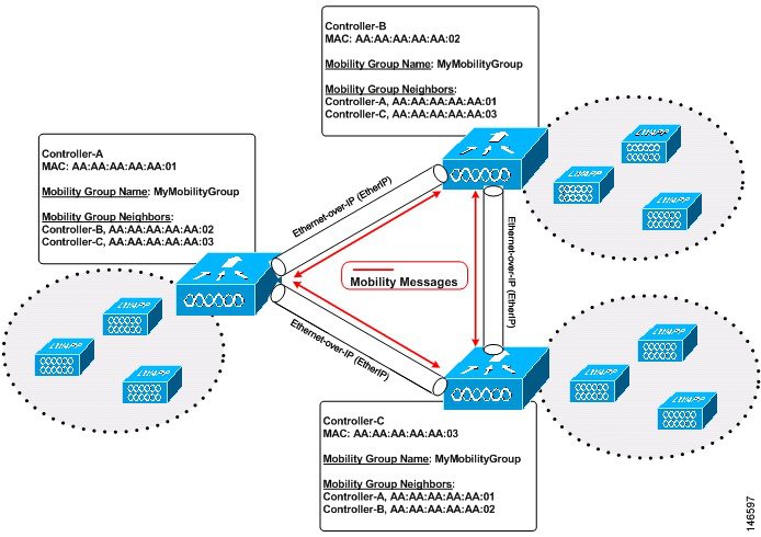
As shown above, each controller is configured with a list of the other members of the mobility group. Whenever a new client joins a controller, the controller sends out a unicast message to all of the controllers in the mobility group. The controller to which the client was previously connected passes on the status of the client. All mobility exchange traffic between controllers is carried over an LWAPP tunnel.
Examples:
1. ![]() A 4404-100 controller supports up to 100 access points. Therefore, a mobility group consisting of 24 4404-100 controllers supports up to 2400 access points (24 * 100 = 2400 access points).
A 4404-100 controller supports up to 100 access points. Therefore, a mobility group consisting of 24 4404-100 controllers supports up to 2400 access points (24 * 100 = 2400 access points).
2. ![]() A 4402-25 controller supports up to 25 access points, and a 4402-50 controller supports up to 50 access points. Therefore, a mobility group consisting of 12 4402-25 controllers and 12 4402-50 controllers supports up to 900 access points (12 * 25 + 12 * 50 = 300 + 600 = 900 access points).
A 4402-25 controller supports up to 25 access points, and a 4402-50 controller supports up to 50 access points. Therefore, a mobility group consisting of 12 4402-25 controllers and 12 4402-50 controllers supports up to 900 access points (12 * 25 + 12 * 50 = 300 + 600 = 900 access points).
Mobility groups enable you to limit roaming between different floors, buildings, or campuses in the same enterprise by assigning different mobility group names to different controllers within the same wireless network. Figure 8-5 shows the results of creating distinct mobility group names for two groups of controllers.
Figure 8-5 Two Mobility Groups
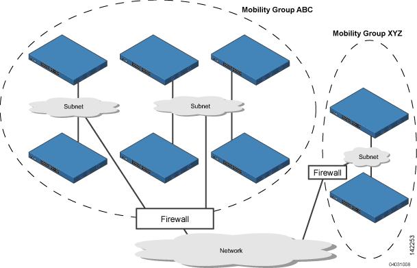
The controllers in the ABC mobility group recognize and communicate with each other through their access points and through their shared subnets. The controllers in the ABC mobility group do not recognize or communicate with the XYZ controllers, which are in a different mobility group. Likewise, the controllers in the XYZ mobility group do not recognize or communicate with the controllers in the ABC mobility group. This feature ensures mobility group isolation across the network.
Note ![]() Clients may roam between access points in different mobility groups, provided they can detect them. However, their session information is not carried between controllers in different mobility groups.
Clients may roam between access points in different mobility groups, provided they can detect them. However, their session information is not carried between controllers in different mobility groups.
When to Include Controllers in a Mobility Group
If it is possible for a wireless client in your network to roam from an access point joined to one controller to an access point joined to another controller, both controllers should be in the same mobility group.
Configuring Mobility Groups
This section provides instructions for configuring mobility groups.
Note ![]() You can also configure mobility groups using the controller. Refer to the Cisco Wireless LAN Controller Configuration Guide for instructions.
You can also configure mobility groups using the controller. Refer to the Cisco Wireless LAN Controller Configuration Guide for instructions.
Prerequisites
Before you add controllers to a mobility group, you must verify that the following requirements have been met for all controllers that are to be included in the group:
•![]() All controllers must be configured for the same LWAPP transport mode (Layer 2 or Layer 3).
All controllers must be configured for the same LWAPP transport mode (Layer 2 or Layer 3).
Note ![]() You can verify and, if necessary, change the LWAPP transport mode on the System > General page.
You can verify and, if necessary, change the LWAPP transport mode on the System > General page.
•![]() IP connectivity must exist between the management interfaces of all devices.
IP connectivity must exist between the management interfaces of all devices.
Note ![]() You can verify IP connectivity by pinging the controllers.
You can verify IP connectivity by pinging the controllers.
•![]() All controllers must be configured with the same mobility group name.
All controllers must be configured with the same mobility group name.
Note ![]() For the Cisco WiSM, both controllers should be configured with the same mobility group name for seamless routing among 300 access points.
For the Cisco WiSM, both controllers should be configured with the same mobility group name for seamless routing among 300 access points.
•![]() All devices must be configured with the same virtual interface IP address.
All devices must be configured with the same virtual interface IP address.
Note ![]() If all the controllers within a mobility group are not using the same virtual interface, inter-controller roaming may appear to work, but the hand-off does not complete, and the client loses connectivity for a period of time.
If all the controllers within a mobility group are not using the same virtual interface, inter-controller roaming may appear to work, but the hand-off does not complete, and the client loses connectivity for a period of time.
•![]() You must have gathered the MAC address and IP address of every controller that is to be included in the mobility group. This information is necessary because you will be configuring all controllers with the MAC address and IP address of all the other mobility group members.
You must have gathered the MAC address and IP address of every controller that is to be included in the mobility group. This information is necessary because you will be configuring all controllers with the MAC address and IP address of all the other mobility group members.
Note ![]() You can find the MAC and IP addresses of the other controllers to be included in the mobility group on the Configure > Controllers page.
You can find the MAC and IP addresses of the other controllers to be included in the mobility group on the Configure > Controllers page.
Follow these steps to add each WLC controller into mobility groups and configure them.
Step 1 ![]() Navigate to Configure > Controllers (see Figure 8-6).
Navigate to Configure > Controllers (see Figure 8-6).
Figure 8-6 Configure > Controllers

This page shows the list of all the controllers you added in Step 1. The mobility group names and the IP address of each controller that is currently a member of the mobility group is listed.
Step 2 ![]() Choose the first controller by clicking on the WLC IP address. You will then access the controller templates interface for the controller you are managing.
Choose the first controller by clicking on the WLC IP address. You will then access the controller templates interface for the controller you are managing.
Step 3 ![]() Select System > Mobility Groups on the left-hand side. The existing Mobility Group members are listed in the window (see Figure 8-7).
Select System > Mobility Groups on the left-hand side. The existing Mobility Group members are listed in the window (see Figure 8-7).
Figure 8-7 Existing Mobility Groups

Step 4 ![]() From the Select a command drop-down menu in the upper right-hand corner, choose Add Group Members and then click GO.
From the Select a command drop-down menu in the upper right-hand corner, choose Add Group Members and then click GO.
Step 5 ![]() You will see a list of available controllers. Choose the desired WLCs and then click Save.
You will see a list of available controllers. Choose the desired WLCs and then click Save.
Step 6 ![]() Repeat Steps 2 through 6 for the remaining WLC devices.
Repeat Steps 2 through 6 for the remaining WLC devices.
Mobility Anchors
Mobility anchors are a subset of a mobility group specified as the anchor controllers for a WLAN. This feature can be used to restrict a WLAN to a single subnet, regardless of the client's entry point into the network. In this way, users can access a public or guest WLAN throughout an enterprise but still be restricted to a specific subnet. Guest WLAN can also be used to provide geographic load balancing because WLANs can represent a particular section of a building (such as, a lobby, a restaurant, and so on).
When a client first associates to a controller of a mobility group that has been preconfigured as a mobility anchor for a WLAN, the client associates to the controller locally, and a local session is created for the client. Clients can be anchored only to preconfigured anchor controllers of the WLAN. For a given WLAN, you should configure the same set of anchor controllers on all controllers in the mobility group.
When a client first associates to a controller of a mobility group that has not been configured as a mobility anchor for a WLAN, the client associates to the controller locally, a local session is created for the client, and the controller is announced to the other controllers in the same mobility group. If the announcement is not answered, the controller contacts one of the anchor controllers configured for the WLAN and creates a foreign session for the client on the local switch. Packets from the client are encapsulated through a mobility tunnel using EtherIP and sent to the anchor controller, where they are decapsulated and delivered to the wired network. Packets to the client are received by the anchor controller and forwarded to the foreign controller through a mobility tunnel using EtherIP. The foreign controller decapsulates the packets and forwards them to the client.
Note ![]() A 2000 series controller cannot be designated as an anchor for a WLAN. However, a WLAN created on a 2000 series controller can have a 4100 series controller or a 4400 series controller as its anchor.
A 2000 series controller cannot be designated as an anchor for a WLAN. However, a WLAN created on a 2000 series controller can have a 4100 series controller or a 4400 series controller as its anchor.
Note ![]() The L2TP Layer 3 security policies are unavailable for WLANs configured with a mobility anchor.
The L2TP Layer 3 security policies are unavailable for WLANs configured with a mobility anchor.
Configuring Mobility Anchors
Follow these steps to create a new mobility anchor for a WLAN.
Step 1 ![]() Click Configure > Controllers .
Click Configure > Controllers .
Step 2 ![]() Choose a controller by clicking an IP address.
Choose a controller by clicking an IP address.
Step 3 ![]() Choose WLANs > WLANs from the left sidebar menu.
Choose WLANs > WLANs from the left sidebar menu.
Step 4 ![]() Click the desired WLAN ID URL (see Figure 8-8).
Click the desired WLAN ID URL (see Figure 8-8).
Figure 8-8 WLAN Window

Step 5 ![]() After choosing a WLAN ID, a tabbed window appears (see Figure 8-9). Click the Advanced tab.
After choosing a WLAN ID, a tabbed window appears (see Figure 8-9). Click the Advanced tab.
Figure 8-9 Mobility Tabbed Window
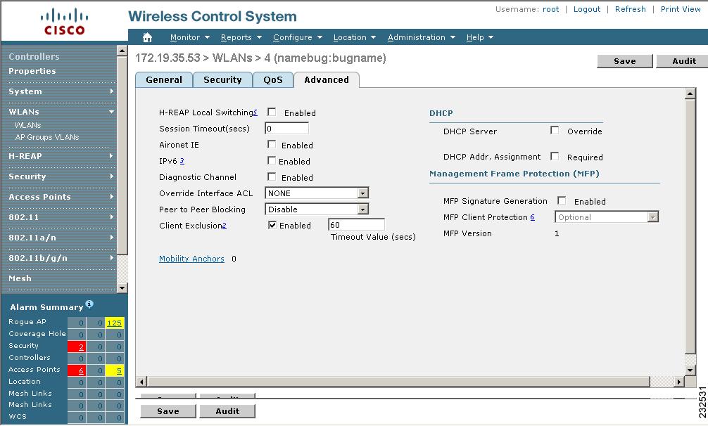
Step 6 ![]() Click the Mobility Anchors link at the bottom of the page. The Mobility Anchors window appears (see Figure 8-10).
Click the Mobility Anchors link at the bottom of the page. The Mobility Anchors window appears (see Figure 8-10).
Figure 8-10 Mobility Anchors

Step 7 ![]() Check the IP address checkbox of the controller to be designated a mobility anchor and click Save.
Check the IP address checkbox of the controller to be designated a mobility anchor and click Save.
Step 8 ![]() Repeat Step 7 and Step 8 to set any other controllers as anchors for this WLAN.
Repeat Step 7 and Step 8 to set any other controllers as anchors for this WLAN.
Step 9 ![]() Configure the same set of anchor controllers on every controller in the mobility group.
Configure the same set of anchor controllers on every controller in the mobility group.
Configuring Multiple Country Codes
You can configure one or more countries on a controller. After countries are configured on a controller, the corresponding 802.11a/n DCA channels are available for selection. At least one DCA channel must be selected for the 802.11a/n network. When the country codes are changed, the DCA channels are automatically changed in coordination.
Note ![]() 802.11a/n and 802.11b/n networks for controllers and access points must be disabled before configuring a country on a controller. To disable 802.11a/n or 802.11b/n networks, 1) choose Configure > Controllers, 2) select the desired controller you want to disable, 3) choose 802.11a/n or 802.11b/g/n from the left sidebar menu, and then 4) choose Parameters. The Network Status is the first check box.
802.11a/n and 802.11b/n networks for controllers and access points must be disabled before configuring a country on a controller. To disable 802.11a/n or 802.11b/n networks, 1) choose Configure > Controllers, 2) select the desired controller you want to disable, 3) choose 802.11a/n or 802.11b/g/n from the left sidebar menu, and then 4) choose Parameters. The Network Status is the first check box.
Follow these steps to add multiple controllers that are defined in a configuration group and then set the DCA channels. To configure multiple country codes outside of a mobility group, refer to the "Setting Multiple Country Codes" section.
Step 1 ![]() Choose Configure > Config Groups.
Choose Configure > Config Groups.
Step 2 ![]() Choose Add Config Groups from the Select a command drop-down menu.
Choose Add Config Groups from the Select a command drop-down menu.
Step 3 ![]() Create a config group by entering the group name and mobility group name.
Create a config group by entering the group name and mobility group name.
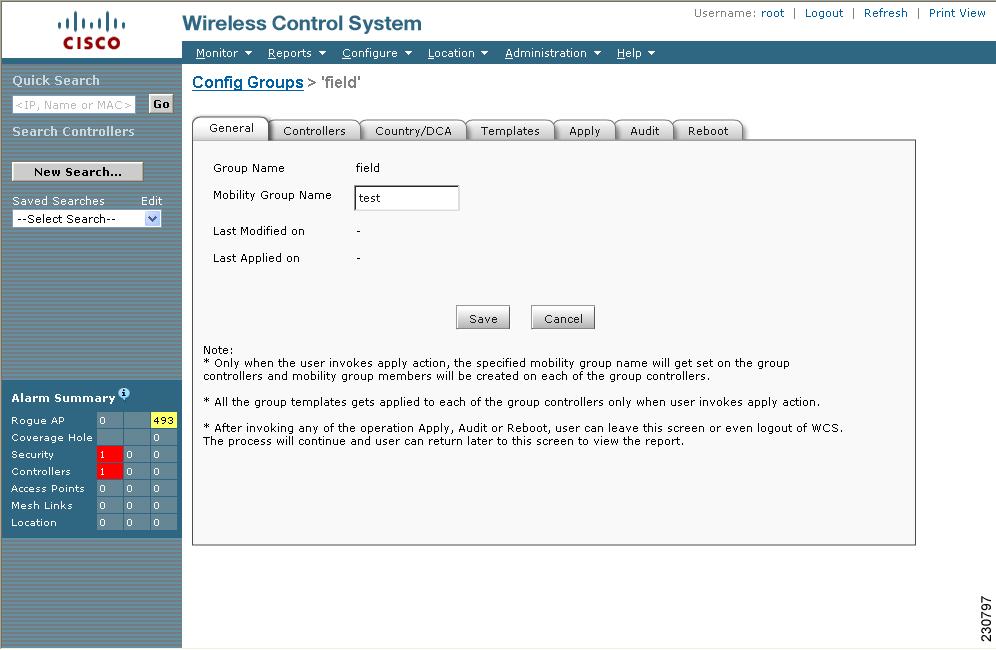
Step 4 ![]() Click Save. The Config Groups window appears (see Figure 8-11).
Click Save. The Config Groups window appears (see Figure 8-11).
Figure 8-11 Config Groups Window
Step 5 ![]() Click the Controllers tab. The Controllers window appears (see Figure 8-12).
Click the Controllers tab. The Controllers window appears (see Figure 8-12).
Figure 8-12 Controller Tab

Step 6 ![]() Highlight the controllers you want to add and click the >> Add button. The controller is added to the Group Controllers window.
Highlight the controllers you want to add and click the >> Add button. The controller is added to the Group Controllers window.
Step 7 ![]() Click the Country/DCA tab. The Country/DCA window appears (see Figure 8-13). Dynamic Channel Allocation (DCA) automatically selects a reasonably good channel allocation amongst a set of managed devices connected to the controller.
Click the Country/DCA tab. The Country/DCA window appears (see Figure 8-13). Dynamic Channel Allocation (DCA) automatically selects a reasonably good channel allocation amongst a set of managed devices connected to the controller.
Figure 8-13 Country/DCA Tab

Step 8 ![]() Check the Update Countries check box to display a list of countries from which to choose.
Check the Update Countries check box to display a list of countries from which to choose.
Step 9 ![]() Those DCA channels that are currently configured on the controller for the same mobility group are displayed in the Select Country Codes window. The corresponding 802.11a/n and 802.11b/n allowable channels for the chosen country is displayed as well. You can add or delete any channels in the list by selecting or deselecting the channel and clicking Save Selection.
Those DCA channels that are currently configured on the controller for the same mobility group are displayed in the Select Country Codes window. The corresponding 802.11a/n and 802.11b/n allowable channels for the chosen country is displayed as well. You can add or delete any channels in the list by selecting or deselecting the channel and clicking Save Selection.
Note ![]() A minimum of 1 and a maximum of 20 countries can be configured for a controller.
A minimum of 1 and a maximum of 20 countries can be configured for a controller.
Creating Config Groups
By creating a config group, you can group controllers that should have the same mobility group name and similar configuration. You can assign templates to the group and push templates to all the controllers in a group. You can add, delete, or remove config groups, and download software, IDS signatures, or a customized web authentication page to controllers in the selected config groups. You can also save the current configuration to nonvolatile (Flash) memory to controllers in selected config groups.
For information about applying templates to either individual controllers or controllers in selected Config Groups, refer to Chapter 10, "Using Templates."
By choosing Configure > Config Groups, you can view a summary of all config groups in the Cisco WCS database. When you choose Add Config Groups from the Select a command drop-down menu, the page displays a table with the following columns:
•![]() Check box: Check to select the config group.
Check box: Check to select the config group.
•![]() Group Name: Name of the config group.
Group Name: Name of the config group.
•![]() Mobility Group Name: Name of Mobility or WPS Group.
Mobility Group Name: Name of Mobility or WPS Group.
•![]() Controllers: Number of controllers added to Config Group.
Controllers: Number of controllers added to Config Group.
•![]() Templates: Number of templates applied to config group.
Templates: Number of templates applied to config group.
•![]() Last Modified: Date and time config group was last modified.
Last Modified: Date and time config group was last modified.
•![]() Last Applied: Date and time last changes were applied.
Last Applied: Date and time last changes were applied.
Adding New Group
Follow these steps to add a config group.
Step 1 ![]() Choose Configure > Config Groups.
Choose Configure > Config Groups.
Step 2 ![]() From the Select a command drop-down list, choose Add Config Group and click GO. The Add New Group window appears (see Figure 8-14).
From the Select a command drop-down list, choose Add Config Group and click GO. The Add New Group window appears (see Figure 8-14).
Figure 8-14 Add New Config Group
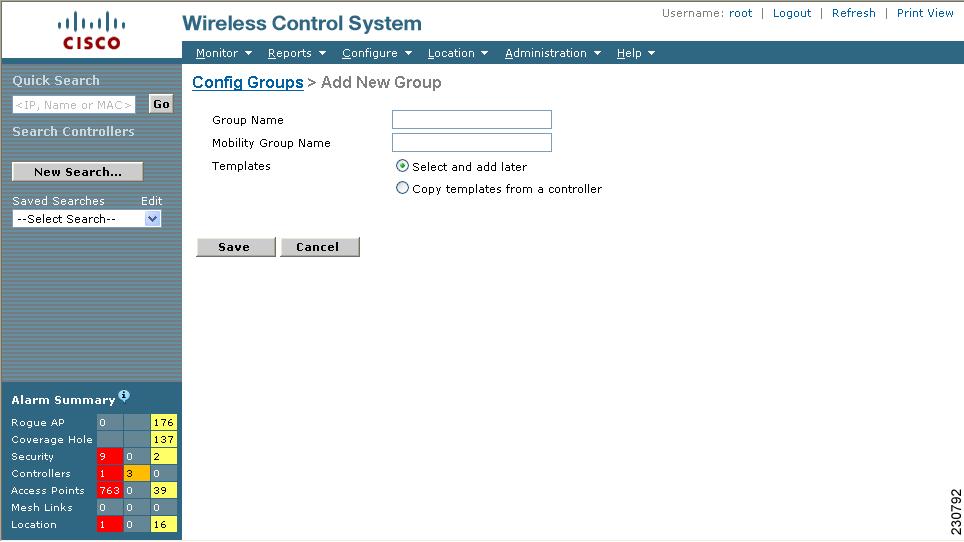
Step 3 ![]() Enter the new config group name. It must be unique across all groups.
Enter the new config group name. It must be unique across all groups.
Step 4 ![]() Enter the mobility group name. Group controllers should have the same mobility group name and similar configuration. This name gets populated to all controllers in the group. Two different config groups can have the same mobility group.
Enter the mobility group name. Group controllers should have the same mobility group name and similar configuration. This name gets populated to all controllers in the group. Two different config groups can have the same mobility group.
Step 5 ![]() Other templates created in WCS can be assigned to a config group. The same WLAN template can be assigned to more than one config group. Choose from the following:
Other templates created in WCS can be assigned to a config group. The same WLAN template can be assigned to more than one config group. Choose from the following:
•![]() Select and add later: Click to add template at a later time.
Select and add later: Click to add template at a later time.
•![]() Copy templates from a controller: Click to copy templates from another controller. Choose a controller from a list of current controllers to copy its applied template to the new config group. Only the templates are copied.
Copy templates from a controller: Click to copy templates from another controller. Choose a controller from a list of current controllers to copy its applied template to the new config group. Only the templates are copied.
•![]() Check the check box to add the selected controller to the new config group, if you want to add the controller.
Check the check box to add the selected controller to the new config group, if you want to add the controller.
Step 6 ![]() Click Save.
Click Save.
Configuring Config Groups
Follow these steps to configure a config group.
Step 1 ![]() Choose Configure > Config Groups, and click a group name under the Group Name column.
Choose Configure > Config Groups, and click a group name under the Group Name column.
Step 2 ![]() Click the General tab. The following options for the config group appear:
Click the General tab. The following options for the config group appear:
•![]() Group Name: Name of the config group
Group Name: Name of the config group
•![]() Mobility Group Name: Mobility Group Name that is pushed to all controllers in the group. The Mobility Group Name can also be modified here.
Mobility Group Name: Mobility Group Name that is pushed to all controllers in the group. The Mobility Group Name can also be modified here.
•![]() Last Modified On: Date and time config group was last modified.
Last Modified On: Date and time config group was last modified.
•![]() Last Applied On: Date and time last changes were applied.
Last Applied On: Date and time last changes were applied.
Step 3 ![]() You must choose the Apply tab to distribute the specified mobility group name to the group controllers and to create mobility group members on each of the group controllers.
You must choose the Apply tab to distribute the specified mobility group name to the group controllers and to create mobility group members on each of the group controllers.
Step 4 ![]() Click Save.
Click Save.
Adding or Removing Controllers from Config Group
Follow these steps to add or remove controllers from a config group.
Step 1 ![]() Choose Configure > Config Groups, and click a group name under the Group Name column.
Choose Configure > Config Groups, and click a group name under the Group Name column.
Step 2 ![]() Click the Controllers tab. The columns in the table display the IP address of the controller, the config group name the controller belongs to, and the controller's mobility group name.
Click the Controllers tab. The columns in the table display the IP address of the controller, the config group name the controller belongs to, and the controller's mobility group name.
Step 3 ![]() Click to highlight the row of the controller you want to add to the group.
Click to highlight the row of the controller you want to add to the group.
Step 4 ![]() Click the >>Add button.
Click the >>Add button.
Note ![]() If you want to remove a controller from the group, highlight the controller in the Group Controllers box and click the << Remove button.
If you want to remove a controller from the group, highlight the controller in the Group Controllers box and click the << Remove button.
Step 5 ![]() You must choose the Apply tab and click the Apply button to add or remove the controllers to the config groups.
You must choose the Apply tab and click the Apply button to add or remove the controllers to the config groups.
Step 6 ![]() Click the Save Selection button.
Click the Save Selection button.
Adding or Removing Templates from the Config Group
Follow these steps to add or remove templates from the config group.
Step 1 ![]() Choose Configure > Config Groups, and click a group name under the Group Name column.
Choose Configure > Config Groups, and click a group name under the Group Name column.
Step 2 ![]() Click the Templates tab. The Remaining Templates table displays the item number of all available templates, the template name, and the type and use of the template.
Click the Templates tab. The Remaining Templates table displays the item number of all available templates, the template name, and the type and use of the template.
Step 3 ![]() Click to highlight the row of the template you want to add to the group.
Click to highlight the row of the template you want to add to the group.
Step 4 ![]() Click the >> Add button.
Click the >> Add button.
Note ![]() If you want to remove a template from the group, highlight the template in the Remaining Templates box and click the << Remove button.
If you want to remove a template from the group, highlight the template in the Remaining Templates box and click the << Remove button.
Step 5 ![]() You must choose the Apply tab and click the Apply button to add or remove the templates to the config groups.
You must choose the Apply tab and click the Apply button to add or remove the templates to the config groups.
Step 6 ![]() Click the Save Selection button.
Click the Save Selection button.
Applying Config Groups
Follow these steps to apply the mobility groups, mobility members, and templates to all the controllers in a config group.
Step 1 ![]() Choose Configure > Config Groups, and click a group name under the Group Name column.
Choose Configure > Config Groups, and click a group name under the Group Name column.
Step 2 ![]() Click the Apply tab to access this page.
Click the Apply tab to access this page.
Step 3 ![]() Click Apply to start the provisioning of mobility groups, mobility members, and templates to all the controllers in the config group. After you apply, you can leave this window or log out of Cisco WCS. The process continues, and you can return later to this page and view a report.
Click Apply to start the provisioning of mobility groups, mobility members, and templates to all the controllers in the config group. After you apply, you can leave this window or log out of Cisco WCS. The process continues, and you can return later to this page and view a report.
Note ![]() Do not perform any other config group functions during the apply provisioning.
Do not perform any other config group functions during the apply provisioning.
A report is generated and displays in the Recent Apply Report window. It shows which mobility group, mobility member, or template were successfully applied to each of the controllers.
Note ![]() If you want to print the report as shown on the window, you must choose landscape page orientation.
If you want to print the report as shown on the window, you must choose landscape page orientation.
Auditing Config Groups
Follow these steps to verify if the controller's configuration complies with the group templates and mobility group.
Step 1 ![]() Choose Configure > Config Groups, and click a group name under the Group Name column.
Choose Configure > Config Groups, and click a group name under the Group Name column.
Step 2 ![]() Click the Audit tab to access this page.
Click the Audit tab to access this page.
Step 3 ![]() Click Audit to verify if the controller's configuration complies with the group templates and the mobility group. During the audit, you can leave this window or logout of Cisco WCS. The process will continue and you can return later to this page and view a report.
Click Audit to verify if the controller's configuration complies with the group templates and the mobility group. During the audit, you can leave this window or logout of Cisco WCS. The process will continue and you can return later to this page and view a report.
Note ![]() Do not perform any other config group functions during the audit verification.
Do not perform any other config group functions during the audit verification.
A report is generated and the current configuration on each controller is compared with that in the config group templates. An audit report for each controller is displayed and includes an option to correct each controller configuration, if needed.
Note ![]() If you want to print the report as shown on the window, you must choose landscape page orientation.
If you want to print the report as shown on the window, you must choose landscape page orientation.
Rebooting Config Groups
Follow these steps to reboot a config group.
Step 1 ![]() Choose Configure > Config Groups, and click a group name under the Group Name column.
Choose Configure > Config Groups, and click a group name under the Group Name column.
Step 2 ![]() Click the Reboot tab.
Click the Reboot tab.
Step 3 ![]() Click the Cascade Reboot check box if you want to reboot one controller at a time, waiting for that controller to come up before rebooting the next controller.
Click the Cascade Reboot check box if you want to reboot one controller at a time, waiting for that controller to come up before rebooting the next controller.
Step 4 ![]() Click Reboot to reboot all controllers in the config group at the same time. During the reboot, you can leave this window or logout of Cisco WCS. The process continues, and you can return later to this page and view a report.
Click Reboot to reboot all controllers in the config group at the same time. During the reboot, you can leave this window or logout of Cisco WCS. The process continues, and you can return later to this page and view a report.
The Recent Reboot Report window shows when each controller was rebooted and what the controller status is after the reboot. If WCS is unable to reboot the controller, a failure is shown.
Note ![]() If you want to print the report as shown on the window, you must choose landscape page orientation.
If you want to print the report as shown on the window, you must choose landscape page orientation.
Downloading Software
Follow these steps to download software to all controllers in the selected groups after you have a config group established.
Step 1 ![]() From Configure > Config Groups, click the check box to choose one or more config groups names on the Config Groups window.
From Configure > Config Groups, click the check box to choose one or more config groups names on the Config Groups window.
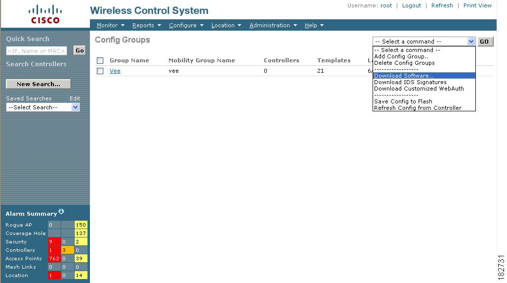
Step 2 ![]() Choose Download Software from the Select a command drop-down menu and click GO (see Figure 8-15).
Choose Download Software from the Select a command drop-down menu and click GO (see Figure 8-15).
Figure 8-15 Download Software Option
Step 3 ![]() The Download Software to Controller window appears. The IP address of the controller to receive the bundle and the current status are displayed. Choose local machine from the File is Located On parameter.
The Download Software to Controller window appears. The IP address of the controller to receive the bundle and the current status are displayed. Choose local machine from the File is Located On parameter.
Step 4 ![]() Enter the maximum number of times the controller should attempt to download the signature file in the Maximum Retries parameter.
Enter the maximum number of times the controller should attempt to download the signature file in the Maximum Retries parameter.
Step 5 ![]() Enter the maximum amount of time in seconds before the controller times out while attempting to download the signature file in the Timeout parameter.
Enter the maximum amount of time in seconds before the controller times out while attempting to download the signature file in the Timeout parameter.
Step 6 ![]() The signature files are uploaded to the c:\tftp directory. Specify the local file name in that directory or use the Browse button to navigate to it. The controller uses this local file name as a base name and then adds _custom.sgi as a suffix.
The signature files are uploaded to the c:\tftp directory. Specify the local file name in that directory or use the Browse button to navigate to it. The controller uses this local file name as a base name and then adds _custom.sgi as a suffix.
If the transfer times out for some reason, you can simply choose the TFTP server option in the File Is Located On parameter, and the Server File Name is populated for you and retried.
Step 7 ![]() Click OK.
Click OK.
Downloading IDS Signatures
Follow these steps to download intrusion detection system (IDS) signature files from your config group to a local TFTP server.
Step 1 ![]() From Configure > Config Groups, click the check box to choose one or more config groups on the Config Groups window.
From Configure > Config Groups, click the check box to choose one or more config groups on the Config Groups window.
Step 2 ![]() Choose Download IDS Signatures from the Select a command drop-down menu and click GO (see Figure 8-16).
Choose Download IDS Signatures from the Select a command drop-down menu and click GO (see Figure 8-16).
Figure 8-16 Downloading IDS Signatures Option

Step 3 ![]() The Download IDS Signatures to Controller window appears. The IP address of the controller to receive the bundle and the current status are displayed. Choose local machine from the File is Located On parameter.
The Download IDS Signatures to Controller window appears. The IP address of the controller to receive the bundle and the current status are displayed. Choose local machine from the File is Located On parameter.
Step 4 ![]() Enter the maximum number of times the controller should attempt to download the signature file in the Maximum Retries parameter.
Enter the maximum number of times the controller should attempt to download the signature file in the Maximum Retries parameter.
Step 5 ![]() Enter the maximum amount of time in seconds before the controller times out while attempting to download the signature file in the Timeout parameter.
Enter the maximum amount of time in seconds before the controller times out while attempting to download the signature file in the Timeout parameter.
Step 6 ![]() The signature files are uploaded to the c:\tftp directory. Specify the local file name in that directory or use the Browse button to navigate to it. The controller uses this local file name as a base name and then adds _custom.sgi as a suffix.
The signature files are uploaded to the c:\tftp directory. Specify the local file name in that directory or use the Browse button to navigate to it. The controller uses this local file name as a base name and then adds _custom.sgi as a suffix.
If the transfer times out for some reason, you can simply choose the TFTP server option in the File Is Located On parameter, and the Server File Name is populated for you and retried.
Step 7 ![]() Click OK.
Click OK.
Downloading Customized WebAuth
Follow these steps to download customized web authentication.
Step 1 ![]() From Configure > Config Groups, click the check box to choose one or more config groups on the Config Groups window.
From Configure > Config Groups, click the check box to choose one or more config groups on the Config Groups window.
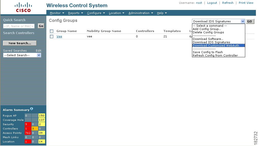
Step 2 ![]() Choose Download Customized WebAuth from the Select command drop-down menu and click GO (see Figure 8-17).
Choose Download Customized WebAuth from the Select command drop-down menu and click GO (see Figure 8-17).
Figure 8-17 Download Customized Web Auth
Step 3 ![]() The Download Customized Web Auth Bundle to Controller window appears. The IP address of the controller to receive the bundle and the current status are displayed (see Figure 8-18).
The Download Customized Web Auth Bundle to Controller window appears. The IP address of the controller to receive the bundle and the current status are displayed (see Figure 8-18).
Figure 8-18 Download Customized Web Auth Bundle to Controller
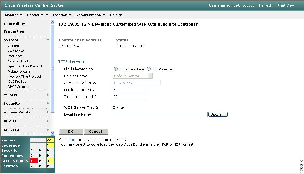
Step 4 ![]() Choose local machine from the File is Located On parameter.
Choose local machine from the File is Located On parameter.
Step 5 ![]() Enter the amount of times the controller should attempt to download the file in the Maximum Retries field.
Enter the amount of times the controller should attempt to download the file in the Maximum Retries field.
Step 6 ![]() Enter the amount of time in seconds before the controller times out while attempting to download the file in the Timeout field.
Enter the amount of time in seconds before the controller times out while attempting to download the file in the Timeout field.
Step 7 ![]() The WCS Server Files In parameter specifies where the WCS server files are located. Specify the local file name in that directory or use the Browse button to navigate to it.
The WCS Server Files In parameter specifies where the WCS server files are located. Specify the local file name in that directory or use the Browse button to navigate to it.
Step 8 ![]() Click OK.
Click OK.
If the transfer times out for some reason, you can simply choose the TFTP server option in the File Is Located On parameter, and the Server File Name is populated for you and retried.
 Feedback