RFC8175-Compliant DLEP Client Support on WGB
This document provides details about configuring RFC8175-compliant Dynamic Link Exchange Protocol (DLEP) client on the Cisco IW3702 access points.
 Note |
The documentation set for this product strives to use bias-free language. For purposes of this documentation set, bias-free is defined as language that does not imply discrimination based on age, disability, gender, racial identity, ethnic identity, sexual orientation, socioeconomic status, and intersectionality. Exceptions may be present in the documentation due to language that is hardcoded in the user interfaces of the product software, language used based on RFP documentation, or language that is used by a referenced third-party product. |
Information about DLEP
DLEP is a radio aware routing (RAR) protocol, which addresses the challenges faced when merging IP routing and radio frequency (RF) communications. Radio Aware Routing (RAR) is a mechanism where radios can interact with routing protocols (such as EIGRP) to signal the appearance, disappearance, and link conditions of one-hop routing neighbors.
The DLEP protocol runs between a router and its attached modems, allowing the modems to communicate link characteristics as they change, and convergence events (acquisition and loss of potential routing next-hops). DLEP provides an event driven mechanism instead of a timer-driven one and enables routing protocols to be radio-aware.
There are two methods for the router to locate its local WGB and set up DLEP sessions: auto discovery and manual configuration.
-
In auto discovery mode, the router initiates the discovery process by sending a peer discovery signal to a well-known UDP multicast IPv4 address 224.0.0.117. Potential WGBs that receive the discovery signal will reply with peer offer and this signal contains the address/port combination. The router will then establish the TCP connection with WGB using that address and port information.
-
In manual configuration method, router will use preconfigured address/port information to initialize the TCP connection directly.
Upon establishment of a TCP connection, the DLEP session will be setup.
Prerequisites and Components Used
The DLEP feature is supported for the following software releases, platforms, and AP Modes:
-
Cisco 5900 Embedded Services Routers, Cisco IOS Release 15.7(3)M2 or greater
-
WGB – Cisco IW3702 access point running autonomous image of Release 15.3(3)JI
-
Wireless LAN Controller (WLC) – Release 8.8
Example Network Topology
The following figure shows a typical topology of DLEP deployment.

In this example, two WGBs are deployed in a vehicle as DLEP clients to provide redundant radio links. Two DLEP sessions are setup between each WGB and the DLEP server, which in this case, is Cisco Embedded Services Router (ESR). Each mesh AP (MAP) is configured with two SSIDs (SSID_A and SSID_B). Each WGB associates to a different SSID and establish a DLEP session with the ESR respectively. WGBs report radio link metrics to ESR through DLEP messages. ESR uses these metrics to cooperate with routing protocol like EIGRP to make better link selection.
Wireless Lan Controller Configuration
This section contains the Wireless Lan Controller configurations. Two WLANs (SSIDs) are required for the redundant radio links.
Procedure
| Step 1 |
Configure AP to FlexConnect mode. 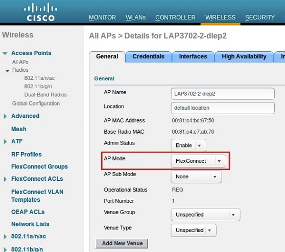 |
||
| Step 2 |
Configure WLAN and VLAN mapping.  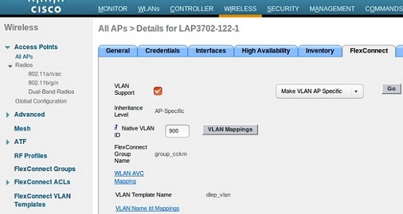 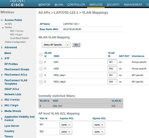 |
||
| Step 3 |
Create two WLAN SSIDs for the redundant radio links, and enable Flexconnect local switching. 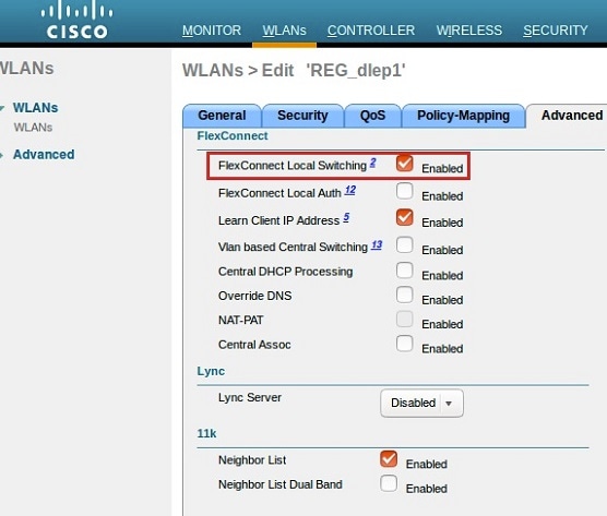
|
Workgroup Bridge Configuration
Two IW3702 APs on the mobile client side should be configured as WGBs to associate to SSID_A and SSID_B respectively.
Follow these steps to configure WGB:
SUMMARY STEPS
- Configure WGB association and radio interface.
- Enable DLEP function on WGB.
- (Optional) Configure DLEP parameters, heartbeat interval and neighbor update interval, under BVI or sub interface that has enabled DLEP.
- Configure DLEP neighbor under the WGB radio interface.
DETAILED STEPS
| Step 1 |
Configure WGB association and radio interface. |
| Step 2 |
Enable DLEP function on WGB. Configure the following command under BVI or Ethernet interface or Ethernet sub-interface to enable DLEP function:
Example:The following example configures DLEP under subinterface: The following example configures DLEP under BVI: |
| Step 3 |
(Optional) Configure DLEP parameters, heartbeat interval and neighbor update interval, under BVI or sub interface that has enabled DLEP. Use the following command to set the interval for the DLEP client to wait before declaring a DLEP server peer failed. The value range of the heartbeat timer is from 1 to 60 seconds. The default value is 5 seconds. The new heartheat timer value will take effect in the next new dlep session. Use the following command to set the interval for DLEP client to send neighbor update event in second. The value range of the heartbeat timer is from 10 to 5000 milliseconds. If not specified, the default value is 4 seconds. The new neighbor update timer will take effect in the next new DLEP session. Neighbor update interval will impact ESR response speed when link state changes. It is recommended to set a shorter neighbor-update-interval for high speed roaming. |
| Step 4 |
Configure DLEP neighbor under the WGB radio interface. |
WGB Configuration Examples
-
Configuration example of WGB1:
Hostname WGB1 dot11 ssid SSID_A authentication open interface Dot11Radio0 no ip address ssid SSID_A antenna gain 0 antenna a-antenna station-role workgroup-bridge dlep neighbor 0050.568f.5ffe uplink-metrics rssi-threshold 60 cdr-threshold 30 mobile station period 1 threshold 70 bridge-group 1 bridge-group 1 spanning-disabled end interface GigabitEthernet0.901 encapsulation dot1Q 901 ip address 100.100.1.12 255.255.255.0 ip dlep gtsm end -
Configuration example of WGB2:
hostname WGB2
dot11 ssid SSID_B
   authentication open

interface Dot11Radio0
no ip address
ssid SSID_B
antenna gain 0
antenna a-antenna
station-role workgroup-bridge
dlep neighbor 0050.568f.acd8
uplink-metrics rssi-threshold 60 cdr-threshold 30
mobile station period 1 threshold 70
bridge-group 1
bridge-group 1 spanning-disabled
end

interface GigabitEthernet0.902
encapsulation dot1Q 901
ip address 100.100.2.12 255.255.255.0
ip dlep gtsm local-port 38682
end
DLEP Server (Local ESR) Configuration
Follow these steps to configure ESR as the DLEP server.
SUMMARY STEPS
- Configure virtual template.
- Configure DLEP draft version 1.27 under Ethernet interfaces with the following command:
- Configure the VMI interface.
- Configure EIGRP with static neighbor.
DETAILED STEPS
| Step 1 |
Configure virtual template. |
||||||||||||
| Step 2 |
Configure DLEP draft version 1.27 under Ethernet interfaces with the following command: Example:The following example enables DLEP draft version 1.27 and uses auto discovery mode to discovery DLEP client. If you need to enable gtsm, use the gtsm keyword. The following example enables DLEP draft version 1.27 and uses preconfigured DLEP client ip address and port number instead of auto discovery mode. |
||||||||||||
| Step 3 |
Configure the VMI interface. |
||||||||||||
| Step 4 |
Configure EIGRP with static neighbor. The link metrics of VMI interface map to the basic EIGRP interface parameters according to the following mapping table:
For more information about this mapping, see Enhanced Interior Gateway Routing Protocol (EIGRP) Wide Metrics White Paper. For the implementation of this feature, relative link quality (RLQ) is the main factor to be considered for link quality. So the default EIGRP metric weights should be updated using the metric weights command.
Example: |
ESR Configuration Example
hostname ESR-Vehicle
!
interface Ethernet0/1
description DLEP radio connection
ip address 100.100.1.1 255.255.255.0
ip dlep vtemplate 1 version v1.27 gtsm
duplex auto
speed auto
!
interface Ethernet0/2
description DLEP radio connection
ip address 100.100.2.1 255.255.255.0
ip dlep vtemplate 2 version v1.27 gtsm client ip100.100.2.12 port 38682
duplex full
speed auto
!
interface Virtual-Template1
ip unnumbered Ethernet0/1
!
interface Virtual-Template2
ip unnumbered Ethernet0/2
!
interface vmi1
ip unnumbered Ethernet0/1
physical-interface Ethernet0/1
!
interface vmi2
ip unnumbered Ethernet0/2
physical-interface Ethernet0/2
!
!
router eigrp 100
 metric weights 0 1 0 1 0 1
 traffic-share min across-interfaces
 network 2.2.2.2 0.0.0.0
 network 100.100.1.0 0.0.0.255
 network 100.100.2.0 0.0.0.255
 neighbor 100.100.1.2 vmi1
 neighbor 100.100.2.2 vmi2
 eigrp router-id 2.2.2.2
Remote ESR Configuration
Configure EIGRP on the remote ESR with static neighbor interface.
hostname ESR-Infra
interface Ethernet0/1
 ip address 100.100.1.2 255.255.255.0

interface Ethernet0/2
 ip address 100.100.2.2 255.255.255.0

router eigrp 100
 network 1.1.1.1 0.0.0.0
 network 100.100.1.0 0.0.0.255
 network 100.100.2.0 0.0.0.255
 neighbor 100.100.1.1 Ethernet0/1
 neighbor 100.100.2.1 Ethernet0/2
 eigrp router-id 1.1.1.1
Verifying the Configuration
Displaying DLEP Configuration
The following command shows information about DLEP configurations, such as the server’s IP address, port, heartbeat threshold, and peer-terminate-ack-timeout value.
WGB#show dlep config
 local udp port=854
 local tcp port=854
 local ipv4=8.1.1.50
 router udp port=55555
 router tcp port=55556
 router ipv4=0.0.0.0

Type Description: no type description
 local ID=0
 peer offer tiemout=5 seconds
 peer heartbeat interval=5 seconds
 peer heartbeat missed threshold=3
 peer termination ack timeout=1000 milliseconds
 peer termination missed ack threshold=3

neighbor up ack timeout=1000 milliseconds
 neighbor up missed ack threshold=3
 neighbor update interval timeout=4000 milliseconds
 neighbor activity timer=5 seconds
 neighbor down ack timeout=1000 milliseconds
 neighbor down missed ack threshold=3
Displaying DLEP Peer Information
The following command provides DLEP peer (DLEP server for WGB) information.
WGB#show dlep peers
DLEP Local Client 2
 Peer Description
 Peer State [Established State]
 Peer UDP port=55555
 Peer TCP port=55556
 Peer IPv4=8.1.1.200
 peer heartbeat=5 seconds
peer heartbeat missed count=0
 peer term ack missed count=0
 peer term ack missed threshold=3
 neighbor up ack timeout=1000 milliseconds
 neighbor up missed ack threshold=3
 neighbor update interval timeout=4000 milliseconds
 neighbor down ack timeout=1000 milliseconds
 neighbor down missed ack threshold=3
Displaying DLEP Neighbors
The following command shows information of DLEP neighbors.
WGB#show dlep neighbors
DLEP Local Client 2
 Client ID=0
 Router ID=0
 Peer Description
 Peer UDP port=55555
 Peer TCP port=55556
 Peer IPv4=8.1.1.200 Neighbor Local ID=5456
 Neighbor MAC: 00:50:56:8F:5F:FE
 Neighbor uptime is 0 hours 0 minutes 20 seconds
 Metrics:
RLQ TX=100 <0-100> RLQ RX=100 <0-100>
 Latency=10 milliseconds
 CDR TX=65399414 bps  CDR RX=66717773 bps
 MDR TX=72000000 bps  MDR RX=72000000 bps
 Maxretry triggered neighbor update: 0
RSSI triggered neighbor update: 0
CDR triggered neighbor update: 0
Displaying DLEP Client Counters
The following command shows packets counters of DLEP client.
WGB1-1A8C#show dlep counters
DLEP Client Counters
Last Clear Time =
DLEP Server IP=8.1.1.200:55556

Peer Counters:
 RX Peer Discovery       1      TX Peer Offer             1
 RX Peer Offer           0      TX Peer Discovery         0
 RX Peer Init            1      TX Peer Init Ack          1
 RX Peer Init Ack        0      TX Peer Init              0
 RX Heartbeat            19     TX Heartbeat              20
 RX Peer Terminate       0      TX Peer Terminate Ack     0
 RX Peer Terminate Ack   0      TX Peer Terminate         0
 RX Peer Update Request  0      TX Peer Update Response   0

Neighbor Counters:
 RX Neighbor Up                 0      TX Neighbor Up Ack                0
 RX Neighbor Up Ack             1      TX Neighbor Up                    1
 RX Neighbor Metric             0      TX Neighbor Metric                29
 RX Neighbor Down               0      TX Neighbor Down Ack              0
 RX Neighbor Down Ack           0      TX Neighbor Down                  0
 Rx Neighbor Announce Request   0      TX Neighbor Announce Response     0
 RX Neighbor Link Char Request  0      TX Neighbor Link Char Response    0
 RX Neighbor Link Char Response 0      TX Neighbor Link Char Request     0

Exception Counters:
 RX Invalid Message    0      RX Unknown Message        0
 RX Unexcepted Message    0      Neighbor Not Found    0

Timer Counters:
 Peer Heartbeat Timer               20
 Peer Terminate Ack Timer           0
 Neighbor Init Ack Timer            0
 Neighbor Metrics Interval Timer    25
 Neighbor Terminate Ack Timer       0
Debug Commands
Note |
Contact your Cisco Support engineer for any troubleshooting support you may need. |
-
The following command triggers the WGB to send peer terminate to the DLEP server to remove the specified peer:
wgb#clear dlep peer -
The following command clears the DLEP client counters:
wgb#clear dlep counters -
The following command displays the DLEP client process event information:
WGB#debug dlep client [detail ] -
The following command displays the DLEP neighbor transaction information:
WGB#debug dlep neighbor {<mac-address >|all |detail |error |metric |state } H.H.H DLEP client neighbor MAC addr all debugging information for all DLEP neighbors detail DLEP neighbor detail information error DLEP neighbor error information metrics DLEP neighbor metrics information state DLEP neighbor state machine information -
The following commands display the DLEP peer transaction information:
WGB#debug dlep peer {detail |error |state |packet {detail |dump |incoming |outgoing }} detail DLEP peer detail information error DLEP peer error information packet display DLEP peer packet information state DLEP peer state machine information WGB#debug dlep peer packet {detail |dump |incoming |outgoing } detail display DLEP client packet details dump display DLEP peer packet as a hex dump incoming filter DLEP client incoming packets outgoing filter DLEP client outgoing packets -
The following commands display the DLEP timer detail information:
WGB#debug dlep timer [detail ]
 Feedback