Cisco IW3702 Access Point Mounting Guide
This guide describes the mounting instructions for the Cisco IW3702 access point.
For more installation and configuration information, see the Cisco IW3702 documentation on Cisco.com.
 Note |
The documentation set for this product strives to use bias-free language. For purposes of this documentation set, bias-free is defined as language that does not imply discrimination based on age, disability, gender, racial identity, ethnic identity, sexual orientation, socioeconomic status, and intersectionality. Exceptions may be present in the documentation due to language that is hardcoded in the user interfaces of the product software, language used based on RFP documentation, or language that is used by a referenced third-party product. |
Conventions
This document uses the following conventions.
|
Conventions |
Indication |
|---|---|
|
bold font |
Commands and keywords and user-entered text appear in bold font. |
|
italic font |
Document titles, new or emphasized terms, and arguments for which you supply values are in italic font. |
|
[ ] |
Elements in square brackets are optional. |
|
{x | y | z } |
Required alternative keywords are grouped in braces and separated by vertical bars. |
|
[ x | y | z ] |
Optional alternative keywords are grouped in brackets and separated by vertical bars. |
|
string |
A nonquoted set of characters. Do not use quotation marks around the string or the string will include the quotation marks. |
|
courier font |
Terminal sessions and information the system displays appear in courier font. |
|
< > |
Nonprinting characters such as passwords are in angle brackets. |
|
[ ] |
Default responses to system prompts are in square brackets. |
|
!, # |
An exclamation point (!) or a pound sign (#) at the beginning of a line of code indicates a comment line. |
Note |
Means reader take note . Notes contain helpful suggestions or references to material not covered in the manual. |
 Caution |
Means reader be careful. In this situation, you might perform an action that could result in equipment damage or loss of data. |
DANGER |
IMPORTANT SAFETY INSTRUCTIONSMeans danger. You are in a situation that could cause bodily injury. Before you work on any equipment, be aware of the hazards involved with electrical circuitry and be familiar with standard practices for preventing accidents. Use the statement number provided at the end of each warning to locate its translation in the translated safety warnings that accompanied this device.SAVE THESE INSTRUCTIONS |
Note |
Regulatory: Provided for additional information and to comply with regulatory and customer requirements. |
Introduction
You can mount the Cisco IW3702 access point in several configurations, including:
-
above a suspended ceiling
-
on a rigid ceiling or wall
-
in an electrical or network box
-
in a vehicle (train, bus, car, van, or truck)
-
on a pole
Mounting Hardware
The Cisco IW3702 access point has built-in mounting flanges. You can also use the following mounting hardware:
-
DIN rail mounting bracket
-
Pole mounting bracket
Required mounting hardware depends on the mounting location:
-
For ceilings or hard ceilings or walls, directly mount the access point using the built-in mounting flanges.
The mounting flanges are on the sides of the access point that are without ports.
-
For electrical cabinets or network boxes, directly mount the access point using the mounting flanges or use the DIN rail mounting bracket.
-
For pole mounting, use the pole mounting bracket.
Mounting Bracket Part Numbers
Note |
These brackets do not ship with the Cisco IW3720 access point, but you can order them separately. |
|
Mounting Bracket |
Cisco Part Number |
|---|---|
|
DIN Rail Mounting Bracket |
AIR-ACCDMK3700= |
|
Pole Mounting Bracket (for 2”–3.2” diameter pole) |
AIR-ACCPMK3700= |
|
Pole Mounting Bracket (for 2”–16” diameter pole) |
AIR-ACCPMK3700-2= |
Mounting the Access Point
Note |
The Cisco IW3702 access point requires free convection air volume. Ensure that the access point has a minimum of 4" (10.16 cm) of unobstructed free space on all sides. |
Using the Integrated Flange Mounts
Direct mounting using the integrated flange mounts is typically for confined spaces or deployments that experience severe shock and vibration.
To mount the access point using the integrated flange mounts:
Procedure
| Step 1 |
Choose the access point location that can safely support the weight of the access point. |
||||||
| Step 2 |
Use the access point mounting holes as a template, and mark them at the mounting location. 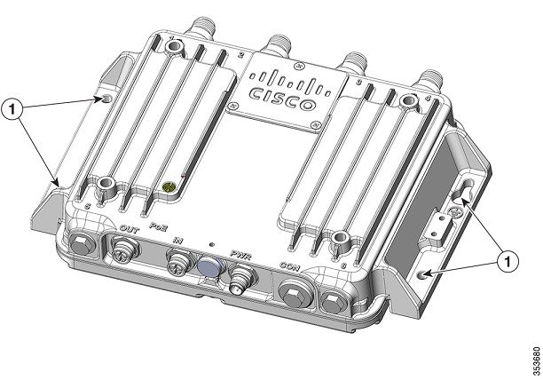
|
||||||
| Step 3 |
Drill holes on the mounting surface for plastic wall anchors to suit 1/4-20 or M6 bolts, and add the appropriate anchors. The following figure shows the hole locations. 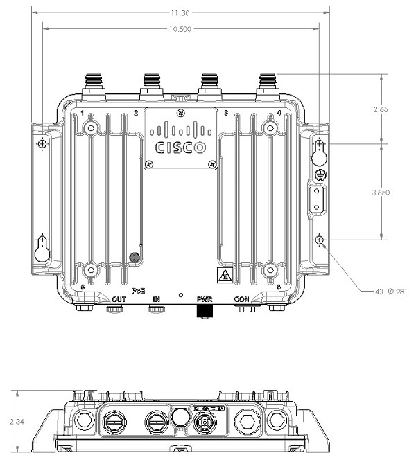 |
||||||
| Step 4 |
Align the access point mounting holes with the suspended ceiling mounting holes. |
||||||
| Step 5 |
Insert a mounting screw in each of the four mounting holes and tighten. |
||||||
| Step 6 |
You can use the keyholes for “hands-free” installation.
|
||||||
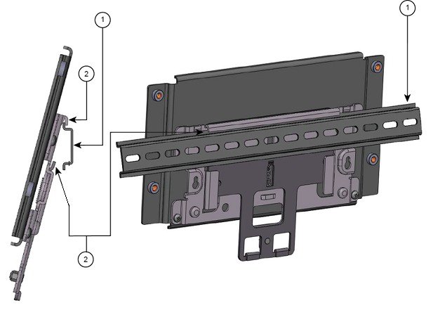
Using the DIN Rail Mounting Bracket
You can use DIN rail mounting in network or electrical closets or cabinets, or in wiring rooms that have low-levels of shock and vibration. Figure 1 shows the DIN rail and DIN rail mounting assembly.
|
1 |
35 mm DIN rail (not supplied by Cisco) |
2 |
DIN rail mounting bracket clip |
To DIN rail mount the access point:
Procedure
| Step 1 |
Assemble the access point and DIN rail mounting bracket using the M6 hardware supplied as shown in the following figure. 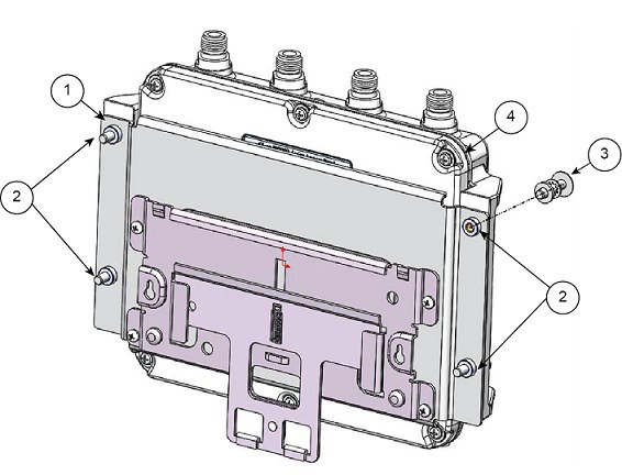
|
||||||||
| Step 2 |
Position the access point assembly directly in front of the DIN rail. |
||||||||
| Step 3 |
Insert the DIN rail mounting bracket under the spring-loaded upper mounting clips. 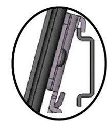
|
||||||||
| Step 4 |
Pull down the retention handles until the lower lip of the DIN rail mounting bracket seats in the lower mounting bracket clip. |
||||||||
| Step 5 |
Release the retention handles. |
Using the Pole Mounting Bracket
You can choose one of the following pole mounting brackets in the following table, according to the size of the pole that you are going to mount your access point on.
|
Mounting Bracket |
Cisco Part Number |
Applicable Pole Diameter |
|---|---|---|
|
Pole Mounting Bracket |
AIR-ACCPMK3700= |
2–3.2 inches |
|
Pole Mounting Bracket 2 |
AIR-ACCPMK3700-2= |
2–16 inches |
Using the Mounting Bracket AIR-ACCPMK3700=
To mount the access point on a pole using the mounting bracket AIR-ACCPMK3700=:
Procedure
| Step 1 |
Use the supplied U bolts, washers, and nuts to attach the mounting bracket to the pole. 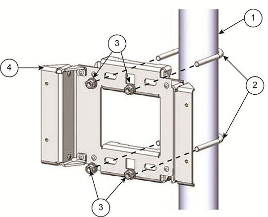
|
||||||||||||||||
| Step 2 |
Use the included bolts, washers, and nuts to attach the access point to the mounting plate.
|
||||||||||||||||
| Step 3 |
Torque the nuts to 6 to 7 foot-pounds. 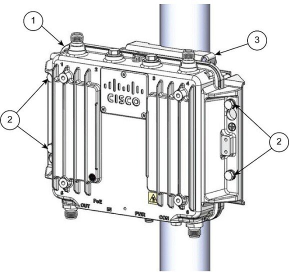
You can use the keyholes for “hands-free” installation. Ensure that you torque the nuts to 6 to 7 ft-lbs.
|
||||||||||||||||
Using the Mounting Bracket AIR-ACCPMK3700-2=
The mounting bracket AIR-ACCPMK3700-2= supports poles from 2 to 16 inches in diameter. To mount the access point on a pole using this mounting bracket:
Procedure
| Step 1 |
Assemble two strap brackets on the pole clamp bracket that are positioned for the pole diameter you are using to mount the access point. The following image illustrates the pole diameter indicators and bolt holes on the pole clamp bracket. 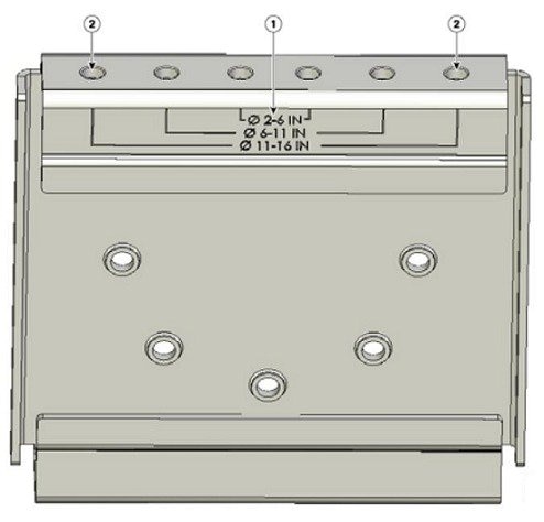
|
||||||||||||||||
| Step 2 |
Position the strap brackets on the pole clamp bracket for the pole diameter you are using and secure each strap bracket with two M8 x16 bolts (with lock washers), as the following image shows. Tighten the bolts to 13 to 15 ft lbs (17.6 to 20.3 N-m). 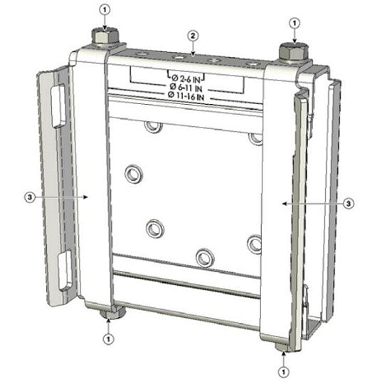
|
||||||||||||||||
| Step 3 |
Screw the M8 nut onto the pole clamp bracket support bolt, and tighten just enough to prevent the bolt from falling off. |
||||||||||||||||
| Step 4 |
To mount your access point on a vertical pole, you need to install two metal bands around the pole to support the access point. This process requires extra tools and material not provided in the pole mount kit (see the following table for details).
|
||||||||||||||||
| Step 5 |
Select a mounting location on the pole to mount the access point. You can attach the access point to any pole from 2 to 16 inch (5.1 to 40.6 cm) in diameter. |
||||||||||||||||
| Step 6 |
For poles larger than 3.5 inch (8.9 cm), mount the pole clamp bracket assembly to a pole (see the following image) using two metal straps. Following the instructions provided with the banding strap tool (BAND IT) (AIR-BAND-INST-TL=), loop each metal strap twice through the slots on the strap bracket.
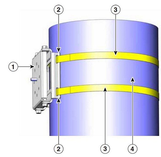
|
||||||||||||||||
| Step 7 |
For pole diameters of 3.5 inch (8.9 cm) or less, mount the pole clamp bracket assembly to a pole using two metal straps looped through the space between the pole clamp bracket and the strap brackets to provide maximum holding strength for extreme environments. Following the instructions provided with the banding strap tool (BAND IT) (AIR-BAND-INST-TL=), loop each metal strap twice.
|
||||||||||||||||
| Step 8 |
Position the pole clamp bracket on the pole as needed before tightening the metal bands.
|
||||||||||||||||
| Step 9 |
Tighten the metal bands using the banding strap tool (BAND IT) (Cisco AIR-BAND-INST-TL=) by following the operating instructions in the box with the tool. Ensure that the metal bands are as tight as possible. |
||||||||||||||||
| Step 10 |
Place the mounting bracket onto the pole clamp bracket support bolt. |
||||||||||||||||
| Step 11 |
Install four M8 x16 bolts (with flat and lock washers) into the bolt holes. 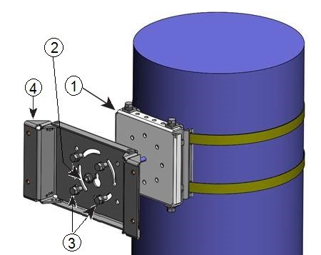
|
||||||||||||||||
| Step 12 |
Hand-tighten the bolts and the nut (do not overtighten). |
||||||||||||||||
| Step 13 |
Adjust the top edge of the mounting bracket until it is horizontal and tighten the bolts and the flange nut to 13 to 15 ft-lbs (17.6 to 20.3 N-m). |
||||||||||||||||
| Step 14 |
Use the included bolts, washers, and nuts to attach the access point to the mounting plate. |
||||||||||||||||
| Step 15 |
Torque the nuts to 6 to 7 ft-lbs. 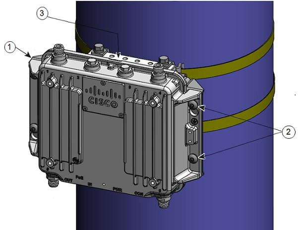
|
||||||||||||||||
Attaching a Power Adapter
If you want to attach a power adapter (AIR-PWRADPT3700NA=, AIR-PWRADPT3700IN=) to the access point on a pole using the mounting bracket AIR-ACCPMK3700= or AIR-ACCPMK3700-2=, use the procedures in the following sections.
Attaching a Power Adapter Using the Mounting Bracket AIR-ACCPMK3700=
To attach a power adapter (AIR-PWRADPT3700NA=, AIR-PWRADPT3700IN=) to the access point on a pole using the mounting bracket AIR-ACCPMK3700=, use the following procedures:
Procedure
| Step 1 |
Ensure you have the mounting bracket set up as described in step 1 of Using the Mounting Bracket AIR-ACCPMK3700=. |
||||||||
| Step 2 |
Attach the power supply using 4x 6-32 screws and torque the screws to 8.3-11 in-lbs, as shown in Figure 1. 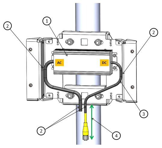
|
||||||||
| Step 3 |
Ensure that the excess cable is bundled and tie wrapped to the mounting bracket. Route the cable as shown in Figure 1. |
||||||||
| Step 4 |
Ensure that there is 10 inches minimum length from the bottom edge of the power supply to the end of the connector as shown in Figure 1. |
||||||||
| Step 5 |
Attach the access point to the mounting plate as described in step 2 and step 3 of Using the Mounting Bracket AIR-ACCPMK3700=. |
Attaching a Power Adapter Using the Mounting Bracket AIR-ACCPMK3700-2=
To attach a power adapter (AIR-PWRADPT3700NA=, AIR-PWRADPT3700IN=) to the access point on a pole using the mounting bracket AIR-ACCPMK3700-2=, use the following procedures:
Procedure
| Step 1 |
Ensure you have the mounting bracket set up as described in step 1 through step 13 of Using the Mounting Bracket AIR-ACCPMK3700-2=. But for step 11, the 2 lower bolts need to be repositioned to the locations indicated as No. 6 in the following figure. |
||||||||||||
| Step 2 |
Attach the power supply using 4x 6-32 screws and torque the screws to 8.3-11 in-lbs, as shown in Figure 1. 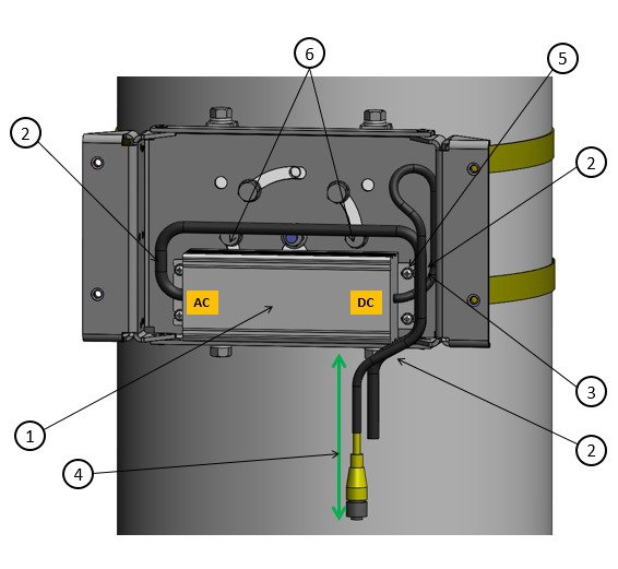
|
||||||||||||
| Step 3 |
Ensure that the excess cable is bundled and tie wrapped to the mounting bracket. Route the cable as shown in Figure 1. |
||||||||||||
| Step 4 |
Ensure that there is 10 inches minimum length from the bottom edge of the power supply to the end of the connector as shown in Figure 1. |
||||||||||||
| Step 5 |
Attach the access point to the mounting plate as described in step 14 and step 15 of Using the Mounting Bracket AIR-ACCPMK3700-2=. |
Grounding an Access Point
For information about how to ground the access point, see the “Grounding the Access Point” section of the Cisco IW3702 Getting Started Guide on Cisco.com.
Related Documentation
-
Cisco IW3702 Access Point Getting Started Guide
 Feedback