Cisco IW3702 Access Point Getting Started Guide
This guide documents the hardware features of the Cisco IW3702 access point. It describes the physical and performance characteristics of each access point, and explains how to install and configure an access point.
This publication is for the network technicians who install and configure access points. You must be familiar with network structures, terms, and concepts.
The Cisco IW3702 access point is referred to as access point in this document.
Organization
This guide includes the following sections:
|
Section |
Description |
|---|---|
|
Describes text conventions used in this document. |
|
|
Describes the major components and features of the access point. |
|
|
Provides warnings, safety information, and installation information you need to install your access point. |
|
|
Provides information about the antennas used by the access point and the antenna configurations deployed. |
|
|
Describes the steps to configure the access point. |
|
|
Lists technical specifications for the access point. |
|
|
Describes the port and connector pinouts for the access point. |
Conventions
This document uses the following conventions.
|
Convention |
Indication |
|---|---|
|
bold font |
Commands and keywords and user-entered text appear in bold font. |
|
italic font |
Document titles, new or emphasized terms, and arguments for which you supply values are in italic font. |
|
[ ] |
Elements in square brackets are optional. |
|
{x | y | z } |
Required alternative keywords are grouped in braces and separated by vertical bars. |
|
[ x | y | z ] |
Optional alternative keywords are grouped in brackets and separated by vertical bars. |
|
string |
A nonquoted set of characters. Do not use quotation marks around the string or the string will include the quotation marks. |
|
courier font |
Terminal sessions and information the system displays appear in courier font. |
|
< > |
Nonprinting characters such as passwords are in angle brackets. |
|
[ ] |
Default responses to system prompts are in square brackets. |
|
!, # |
An exclamation point (!) or a pound sign (#) at the beginning of a line of code indicates a comment line. |
 Note |
Means reader take note . Notes contain helpful suggestions or references to material not covered in the manual. |
 Caution |
Means reader be careful. In this situation, you might perform an action that could result in equipment damage or loss of data. |
DANGER |
IMPORTANT SAFETY INSTRUCTIONSMeans danger. You are in a situation that could cause bodily injury. Before you work on any equipment, be aware of the hazards involved with electrical circuitry and be familiar with standard practices for preventing accidents. Use the statement number provided at the end of each warning to locate its translation in the translated safety warnings that accompanied this device.SAVE THESE INSTRUCTIONS |
Overview
This document describes the Cisco IW3702 access point. The access point is an IEEE 802.11a/b/g/n/ac compliant, dual-band WiFi access point with external antennas.
The access point is IP67 rated, ruggedized, and certified for on-board rail and outdoor use-cases such as train and trackside, mining, intelligent transportation systems, and smart city applications. You can mount the access point on a DIN rail in an industrial enclosure. Its components are designed to withstand extremes in temperature, vibration, and shock common in industrial environments.
The access point features:
-
IEEE 802.11a/b/g/n compliant operation
-
IEEE 802.11ac Wave 1 support
-
Dual-radio design for 2.4 GHz and/or 5 GHz bands
-
4x4 multiple-input multiple-output (MIMO) technology with three spatial streams
-
Cisco CleanAir support for 20, 40, and 80 MHz channels
-
DC input port (M12 connector)
-
2 Power over Ethernet (PoE) ports with M12 X-code connectors:
-
1 x PoE-IN Gigabit Ethernet port compliant with IEEE 802.3at POE+ PD
-
1 x PoE-OUT Gigabit Ethernet port compliant with IEEE 802.3af POE PSE
-
-
RS232 console port with cover (RJ-45 connector)
-
4 antenna ports (N connector-female)
-
Rugged IP67 rated housing and -40 to 167°F (-40 to 75°C) operating temperature range (ambient—without solar loading or wind cooling)
-
Compact size for space constrained environments
Access Point Models
There are two access point models, based on antenna configuration. The following table lists the available IW3702 models.
|
Model |
Description |
|---|---|
|
Cisco IW3700 Series Access Points with Regulatory Domain Code1 |
|
|
IW3702-2E-x-K9 |
Access point with four antenna connectors: 2 on the top and 2 on the bottom. |
|
IW3702-4E-x-K9 |
Access point with four antenna connectors on top side. |
|
Cisco IW3700 Series Universal Access Points |
|
|
IW3702-2E-UXK9 |
Access point with four antenna connectors: 2 on the top and 2 on the bottom. |
|
IW3702-4E-UXK9 |
Access point with four antenna connectors on top side. |
Note |
Cisco IW3700 Series Access Points with regulatory domain mapping for the country code Egypt "EG" with 2.4G: "-E" and 5G: "-I" is supported from Cisco AireOS Release 8.5 and Cisco IOS-XE Release 17.3. |
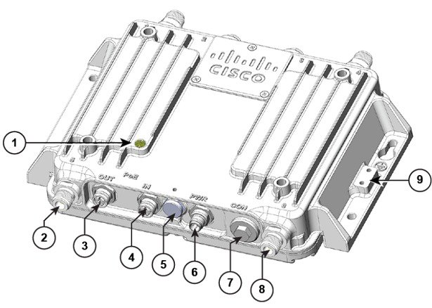
Bottom and Top Panel Views
|
1 |
Status LED |
6 |
Power (PWR) connector |
|
2 |
Antenna port B |
7 |
Console (CON) port |
|
3 |
PoE OUT port |
8 |
Antenna port A |
|
4 |
PoE IN port |
9 |
Ground connection |
|
5 |
Protective vent port / Reset button (covered) |
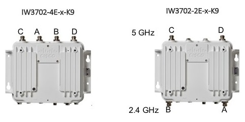
Note |
There are four antenna ports on the Cisco IW3702-2E-UXK9/IW3702-2E-x-K9 model: two on the top and two on the bottom. |
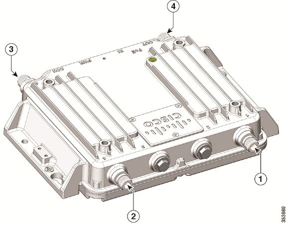
|
1 |
Antenna port C |
3 |
Antenna port A |
|
2 |
Antenna port D |
4 |
Antenna port B |
Note |
There are four antenna ports on the Cisco IW3702-4E-UXK9/IW3702-4E-x-K9 model: all four connectors are on the top side. |
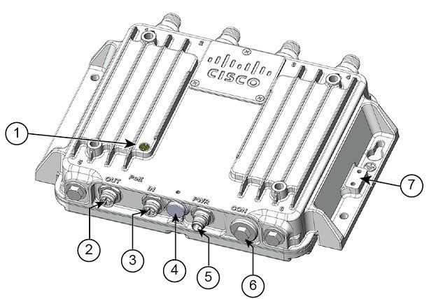
|
1 |
Status LED |
5 |
Power (PWR) connector |
|
2 |
PoE OUT port |
6 |
Console (CON) port |
|
3 |
PoE IN port |
7 |
Ground connection |
|
4 |
Protective vent port / Reset button (covered) |
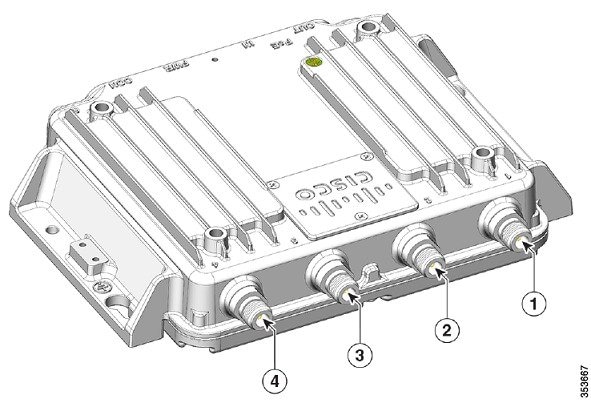
|
1 |
Antenna port C |
3 |
Antenna port B |
|
2 |
Antenna port A |
4 |
Antenna port D |
Bottom Panel Components
This section describes the bottom panel components.
Status LED
The Status LEDs provide information on access point status, activity, and performance. The following table describes status LED states.
|
Message Type |
LED Color |
System State |
|---|---|---|
|
Boot loader status |
Blinking pink |
DRAM memory test in progress. |
|
DRAM memory test OK. |
||
|
Board initialization in progress. |
||
|
Initializing flash file system. |
||
|
Flash memory test OK. |
||
|
Initializing Ethernet. |
||
|
Ethernet OK. |
||
|
Starting Cisco IOS. |
||
|
Initialization successful. |
||
|
Client association status |
Green |
Normal operating condition but no wireless client association. |
|
Blue |
Normal operating condition with at least one wireless client association. |
|
|
Operational status |
Blinking blue |
Software upgrade in progress. |
|
Cycling green-red-off |
Discovery/join process in progress. |
|
|
Rapidly cycling blue-green-red |
Access point location command invoked. |
|
|
Blinking red |
Ethernet link not operational. |
|
|
Boot loader warnings |
Blinking blue |
Configuration recovery in progress (RESET button pushed for 30 seconds). |
|
Red |
Ethernet failure or image recovery (RESET button pushed for 50 seconds). |
|
|
Blinking pink |
Image recovery in progress (MODE button released). |
|
|
Boot loader errors |
Red |
DRAM memory test failure. |
|
Blinking red-blue |
FLASH file system failure. |
|
|
Blinking red-off |
Environment variable failure. |
|
|
Bad MAC address. |
||
|
Ethernet failure during image recovery. |
||
|
Boot environment failure. |
||
|
No Cisco image file. |
||
|
Boot failure. |
||
|
Cisco IOS errors |
Red |
Software failure. Disconnect and reconnect unit power. |
|
Cycling blue-green-red-off |
General warning. Insufficient inline power. |
|
|
AP status when provisioned by Cisco AirProvision |
Cycling red-green-off |
AP waiting to be primed. |
|
Blinking white |
AP priming via Cisco NDP in progress. |
|
|
Blinking teal (for 15 seconds) |
AP upon successful connection to Cisco AirProvision. |
|
|
Blinking blue |
AP priming via Cisco AirProvision in progress. |
|
|
Chirping red |
AP primed to wrong regulatory domain. |
PWR Connectors
There are two options for powering the access point:
-
DC input over the PWR connector.
-
PoE inline power over the PoE IN port.
Note |
When powering the access point:
|
The access point requires a DC power supply. To power the access point with a DC power supply, you connect the DC power to the PWR connector on the bottom panel. The DC input voltage range is +12 to +48 VDC (-20%, +25%).
The PWR connector is an M12 A-code, 4-pin (male) connector. See Power Port and DC Input and PoE IN Specifications.
PoE OUT Port
Note |
The PoE OUT port is only supported when the access point is powered over the PWR port. When powered over the PoE IN port, PoE OUT functionality is not supported. |
The PoE OUT port is a 10/100/1000 BASE-T port with an M12 X-code connector. The PoE OUT port supplies PoE inline DC power to power external devices. The PoE OUT port pin-out conforms to Alternative A-MDIX mode.
Note |
PoE inline power supports IEEE 802.3af compliant devices and delivers up to 15.4 W of PoE. |
For more information about the PoE OUT, PoE IN, and DC input, see DC Input and PoE IN Specifications.
PoE IN Port
The PoE IN port is a 10/100/1000 BASE-T port with an M12 X-code connector. The port has auto-sensing and auto-MDIX capabilities.
Note |
The PoE IN port is an alternate power input to DC input over the PWR port. |
-
Power the access point over the PWR port to enable the PoE OUT port.
-
When powered over the PoE IN port, PoE OUT functionality is not supported.
For more information, see DC Input and PoE IN Specifications.
Protective Vent Port
The protective vent port relieves pressure inside the access point chassis possibly caused by changing temperatures in the installation environment. The vent prevents pressure from building up and damaging enclosure seals and potentially exposing sensitive components to water. The vent also protects the access point interior from dust, dirt, water, and other environmental elements.
Note |
If the vent is removed or damaged, the access point is subject to moisture damage. |
Reset Button
You use the reset button for configuration or image recovery. The reset button is under the protective vent port. To access the reset button:
-
Use a 5/8" socket to remove the protective vent.
-
Disconnect power (the power jack for external power or the Ethernet cable for in-line power) from the access point.
-
Press and hold the RESET button while you reconnect power to the access point.
-
Press the reset button.
-
Hold the RESET button until the Status LED turns blinking blue (usually, pushed for 30 seconds) to reset the access point to its factory settings.
-
Hold the RESET button until the Status LED turns solid Red (usually, pushed for 50 seconds) to do image recovery.
-
-
Replace the protective vent using 5/8" socket.
-
Torque the protective vent to 5-7 inch-lbs.
Console Port
You can connect the access point to a PC or laptop through the RJ45 CON port. The RJ45 CON port uses the Cisco console port RJ45-to-DB9 cable (Cisco PN 72-3383-01).
A cable port seal covers the CON port. This liquid-tight plug protects the access point from environmental elements. Ensure that the plug is installed during normal operation or when unit is unattended. You can remove and install the port plug with a 1/2" (13 mm) socket. Torque it to 6-7 ft-lbs
For more information, see Console Port.
Ground Stud
The ground stud is the access point ground. You use screws to attach the wired grounding lug to the ground stud. Connect the other end of the ground wire to an earth ground such as a grounding rod or appropriate ground point on a grounded pole.
Top Panel Components
This section describes the top panel components.
Antenna Port
The antenna connector is a type N female coaxial connector.
Hard Points
The hard points are alternate mounting or attachment points for additional equipment such as directional antennas or covers.
Note |
Do not attach third-party radios using these hard points. |
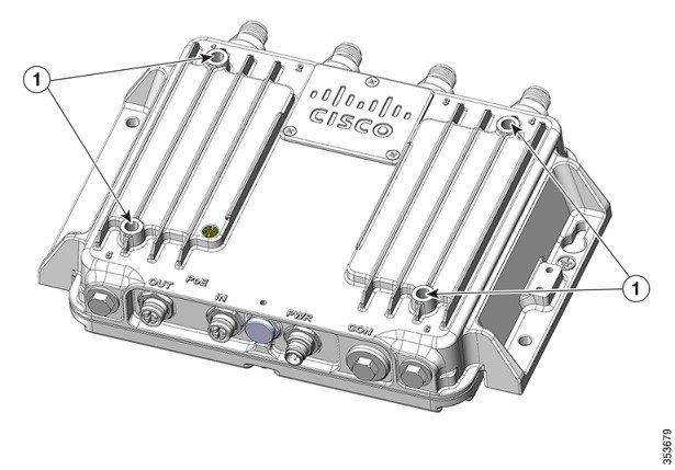
|
1 |
Hard points 1/4-20UNC-2B, .45" deep |
Management Options
You can manage the access point using the following options:
-
Web browser Interface—Contains management pages to change the wireless device settings, upgrade firmware, and monitor and configure other wireless devices on the network.
-
Cisco IOS command-line interface (CLI)—Configures the access point. You can access the CLI by directly connecting a PC to the console port, or you can access the CLI using a Telnet session from a remote management station.
Installation
You can install the access point on a wall, ceiling or pole, in a cabinet or rack, under a seat, or in a plenum airspace. You can direct mount, DIN rail mount, or attach the access point on a pole mounting bracket.
Perform the installation procedures in this order:
Preparing for Installation
The following topics prepare you for installing the unit:
Warnings
These warnings are translated into several languages in the Regulatory Compliance and Safety Information for the Cisco IW3702 Access Point on Cisco.com.
DANGER |
Only trained and qualified personnel should be allowed to install, replace, or service this equipment. Statement 1030 |
DANGER |
In order to comply with FCC radio frequency (RF) exposure limits, antennas for this product should be located a minimum of 7.9 in. (20 cm) or more from the body of all persons. Statement 332 |
DANGER |
Read the installation instructions before you connect the system to its power source. Statement 1004 |
DANGER |
This unit is intended for installation in restricted access areas. A restricted access area can be accessed only through the use of a special tool, lock and key, or other means of security. Statement 1017 |
DANGER |
This equipment must be grounded. Never defeat the ground conductor or operate the equipment in the absence of a suitably installed ground conductor. Contact the appropriate electrical inspection authority or an electrician if you are uncertain that suitable grounding is available. Statement 1024 |
DANGER |
Ultimate disposal of this product should be handled according to all national laws and regulations. Statement 1040 |
DANGER |
To prevent the system from overheating, do not operate it in an area that exceeds the maximum recommended ambient temperature of: 70°C Statement 1047 |
DANGER |
Installation of the equipment must comply with local and national electrical codes. Statement 1074 |
DANGER |
This product relies on the building’s installation for short-circuit (overcurrent) protection. Ensure that the protective device is rated not greater than: 15 A. Statement 1005 |
DANGER |
Do not operate your wireless network device near unshielded blasting caps or in an explosive environment unless the device has been modified to be especially qualified for such use. Statement 245B |
Caution |
The fasteners you use to mount an access point on a ceiling must be capable of maintaining a minimum pullout force of 20 lbs (9 kg) and must use all 4 indented holes on the mounting bracket. |
Note |
The access point is suitable for use in environmental air space in accordance with section 300.22.C of the National Electrical Code and sections 2-128, 12-010(3), and 12-100 of the Canadian Electrical Code, Part 1, C22.1. You should not install the power supply or power injector in air handling spaces. |
Note |
Use only with listed ITE equipment. |
EMC Environmental Conditions for Products Installed in the European Union
This section applies to products installed in the European Union. The equipment is intended to operate under the following environmental conditions with respect to EMC:
-
A separate defined location under the user’s control.
-
Earthing and bonding meets the requirements of ETSI EN 300 253 or ITU-T K.27.
-
AC-power distribution shall be one of the following types, where applicable: TN-S and TN-C as defined in IEC 60364-3.
In addition, if equipment is operated in a domestic environment, interference could occur.
National Restrictions within the European Union
Within the European Union as well as within the majority of the other European Countries, the 2.4 and 5 GHz bands are available for use by wireless LANs.
The following table provides an overview of the regulatory requirements that are generally applicable for 2.4 and 5 GHz bands.
The requirements for any country might evolve. We recommend that you check with your local authorities for the current status of regulations for 2.4 and 5 GHz wireless LANs within your country.
|
Frequency Band (MHz) |
Maximum Power Level Effective Isotropic Radiated Power (EIRP) mW |
Indoor only |
Indoor and Outdoor |
|---|---|---|---|
|
2400-2483.5 |
100 |
— |
x |
|
5150-5350 |
200 |
x |
— |
|
5470-5725 |
1000 |
— |
x |
Tools and Hardware Required
These tools and hardware are required for access point installation:
-
Crimping tool (such as Thomas & Bett part number WT2000, ERG-2001, or equivalent)
-
6-gauge copper ground wire
-
Wire-stripping tools for stripping 6-gauge wire
-
Number 2 Phillips screwdriver
-
1/2" (13 mm) socket for port plug
-
5/8" (16 mm) socket for protective vent
-
5/32" (4 mm) hex key for mounting screws
-
Torque wrench (both inch-lbs and ft-lbs)
Installation Guidelines
Because the access point is a radio device, it is susceptible to common causes of interference that can reduce throughput and range. Follow these guidelines to ensure the best possible performance:
-
For information on planning and initially configuring your Cisco Mesh network, refer to the Cisco Wireless Mesh Access Points, Design and Deployment Guide.
-
Review the FCC Guidelines for Installation and Operation of Outdoor Wireless LAN Devices (U-NII devices) Operating in the 5470-5725 MHz Band Data Sheet at: http://www.cisco.com/c/en/us/products/collateral/routers/3200-series-rugged-integrated-services-routers-isr/data_sheet_c78-647116.html
The above document provides guidelines to mitigate interference to Federal Aviation Administration (FAA) Terminal Doppler Weather Radar (TDWR) as well as details on registering your access point with the Wireless Internet Service Providers Association (WISPA).
-
Perform a site survey before beginning the installation.
-
Install the access point in an area where structures, trees, or hills do not obstruct radio signals to and from the devices.
-
For information on priming a Cisco universal access point, see the Cisco Aironet Universal AP Priming and Cisco AirProvision User Guide at: http://www.cisco.com/c/en/us/td/docs/wireless/access_point/ux-ap/guide/uxap-mobapp-g.html
Site Surveys
Every network application is a unique installation. Before installing an access point, perform a site survey to determine the optimum use of networking components and maximize range, coverage, and network performance.
Consider the following operating and environmental conditions when performing a site survey:
-
Data rates—Sensitivity and range are inversely proportional to data bit rates. The maximum radio range is achieved at the lowest workable data rate. A decrease in receiver sensitivity occurs as the radio data increases.
-
Antenna type and placement—Proper antenna configuration is a critical factor in maximizing radio range. As a general rule, range increases in proportion to antenna height. However, do not place the antenna higher than necessary, because extra height increases potential interference from other unlicensed radio systems and decreases the wireless coverage from the ground.
-
Physical environment—Clear or open areas provide better radio range than closed or filled areas.
-
Obstructions—Physical obstructions such as buildings, trees, or hills can hinder performance of wireless devices. Avoid locating the devices in a location where an obstruction exists between the sending and receiving antennas.
Unpacking the Components
The typical access point package contains the following items:
-
Access point
-
Cisco product documentation and translated safety warnings
-
Ground lug (Panduit PLCD6-10A-L), screws, and oxide inhibitor (contained in a tube)
-
Console cable
-
CoaxSeal—Coaxial cable/connector seal tape for N connectors
-
Two M12 Ethernet connector caps (installed on the PoE OUT and PoE IN ports)
-
One M12 power connector cap (installed on the PWR port)
Note |
The M12 connector caps are installed on the ports for protection when the AP is shipped. Remove the caps before using the ports. See the following figure for the locations of each port with M12 cap. |
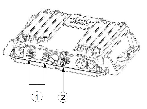
|
1 |
PoE ports with caps |
2 |
PWR connector with cap |
To unpack the access point:
SUMMARY STEPS
- Open the shipping container and carefully remove the contents.
- Return all packing materials to the shipping container, and save it.
- Ensure that all the access point package items are included in the shipment.
DETAILED STEPS
|
Step 1 |
Open the shipping container and carefully remove the contents. |
|
Step 2 |
Return all packing materials to the shipping container, and save it. |
|
Step 3 |
Ensure that all the access point package items are included in the shipment. |
What to do next
Note |
If any item is damaged or missing, notify your sales representative. |
Mounting the Access Point
For instructions about mounting the access point, see the Cisco IW3702 Access Point Mounting Guide
Connecting the Protective Ground and Power
Perform the following steps in order when connecting the access point to power and ground.
Grounding the Access Point
In all installations, after mounting the access point, you must properly ground the unit before connecting power cables.
DANGER |
This equipment must be grounded. Never defeat the ground conductor or operate the equipment in the absence of a suitably installed ground conductor. Contact the appropriate electrical inspection authority or an electrician if you are uncertain that suitable grounding is available. Statement 1024 |
DANGER |
Installation of the equipment must comply with local and national electrical codes. Statement 1074 |
The access point is shipped with a grounding kit.
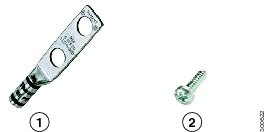
|
1 |
Grounding lug |
|
2 |
Screws x 2, M4 x 6mm |
Note |
The grounding kit also includes the oxide inhibitor, which is contained in a tube. |
To ground the access point:
SUMMARY STEPS
- Use a crimping tool to crimp a 6-AWG ground wire (not included in the grounding kit) to the ground lug.
- Connect the supplied ground lug to the access point ground connection point using the supplied screws. Apply supplied oxide inhibitor between the ground lug and the access point ground connection.
- Tighten the screws to 20-25 inch-lbs of torque.
- If necessary, strip the other end of the ground wire and connect it to a reliable earth ground such as a grounding rod or appropriate ground point on a grounded pole. Length of the ground cable should not exceed 1 meter, and 0.5 meter is preferred. Use supplied oxide inhibitor on the grounded interface.
DETAILED STEPS
|
Step 1 |
Use a crimping tool to crimp a 6-AWG ground wire (not included in the grounding kit) to the ground lug. 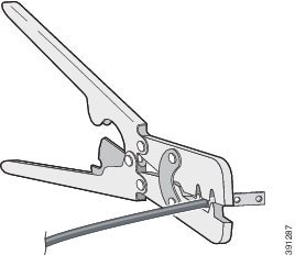 |
||
|
Step 2 |
Connect the supplied ground lug to the access point ground connection point using the supplied screws. Apply supplied oxide inhibitor between the ground lug and the access point ground connection. |
||
|
Step 3 |
Tighten the screws to 20-25 inch-lbs of torque. 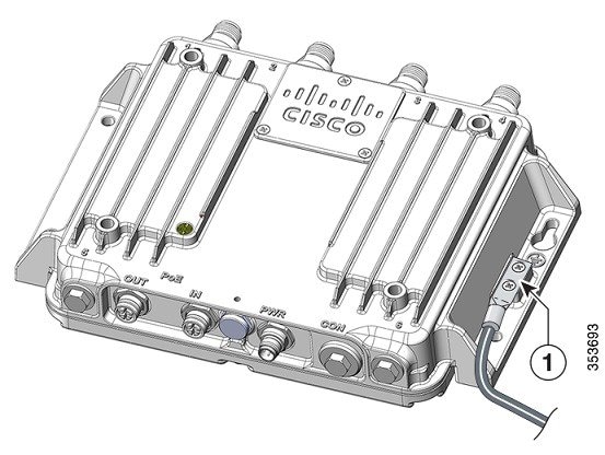
|
||
|
Step 4 |
If necessary, strip the other end of the ground wire and connect it to a reliable earth ground such as a grounding rod or appropriate ground point on a grounded pole. Length of the ground cable should not exceed 1 meter, and 0.5 meter is preferred. Use supplied oxide inhibitor on the grounded interface. |
Wiring the Access Point DC Power
To wire the access point to a DC power source:
SUMMARY STEPS
- Verify that the access point is grounded (see Grounding the Access Point).
- Connect the power lead to the PWR connector by turning the cable clockwise, as shown in the following figure.
- Connect the other end of the power cable to the DC power source using the power source wiring instructions. The PWR connector pinout descriptions are in Power Port.
DETAILED STEPS
|
Step 1 |
Verify that the access point is grounded (see Grounding the Access Point). |
||
|
Step 2 |
Connect the power lead to the PWR connector by turning the cable clockwise, as shown in the following figure. 
|
||
|
Step 3 |
Connect the other end of the power cable to the DC power source using the power source wiring instructions. The PWR connector pinout descriptions are in Power Port. |
Connecting the Antennas
Connect each antenna based on:
-
Antenna arrangement, cabling, lightning arrestor, and adapter information in Examples of Access Point and Antenna Deployment Configurations.
-
Installation information in Antenna Types and Models.
Connecting to Access Point Ports
This section describes connecting the access point to PoE.
DANGER |
For connections outside the building where the equipment is installed, the following ports must be connected through an approved network termination unit with integral circuit protection.10/100/1000 Ethernet Statement 1044 |
Connecting to the PoE IN or PoE OUT Port
SUMMARY STEPS
- Use shielded cables with a M12 X-Code plug to connect to the PoE IN or PoE OUT ports.
- Connect the PoE IN cable to the PoE IN port, or the PoE OUT cable to the PoE OUT port by turning the cable clockwise, as shown in the following figure.
DETAILED STEPS
|
Step 1 |
Use shielded cables with a M12 X-Code plug to connect to the PoE IN or PoE OUT ports.
|
||||||
|
Step 2 |
Connect the PoE IN cable to the PoE IN port, or the PoE OUT cable to the PoE OUT port by turning the cable clockwise, as shown in the following figure. 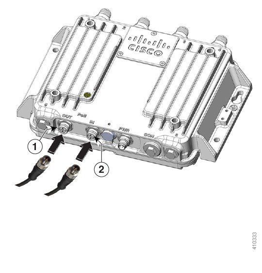
|
Antennas and RF Accessories
This section describes antennas, RF Accessories, and their configuration for the access point.
Cisco recommends using a coax seal (such as CoaxSeal) for outdoor connections, to prevent moisture and other weathering elements from affecting performance. For more information on using coax seal on the N connector to cable or antenna interface, see the instructions on your antenna documents.
Antenna Types and Models
The antennas used in these configurations are:
-
Cisco Aironet Dual-Band Omnidirectional Antenna (White model—Cisco PID AIR-ANT2547V-N)
Cisco Aironet Dual-Band Omnidirectional Antenna (Cisco PID AIR-ANT2547VG-N)
These are the related models:
-
White model (Cisco PID AIR-ANT2547V-N=)
-
Grey Model (Cisco PID AIR-ANT2547VG-N=)
-
-
Cisco Aironet Four-Port Dual-Band Polarization-Diverse Array Antenna (Cisco PID AIR-ANT2513P4M-N)
-
Cisco Aironet Dual-Band MIMO Wall-Mounted Omnidirectional Antenna (Cisco PID AIR-ANT2544V4M-R)
-
Cisco Aironet 2.4 GHz/5 GHz MIMO 4-Element Patch Antenna (Cisco PID AIR-ANT2566P4W-R)
-
Cisco Aironet 2.4-GHz 13-dBi Directional Antenna (Cisco PID AIR-ANT2413P2M-N)
-
Cisco Aironet 5-GHz 13-dBi Directional Antenna (Cisco PID AIR-ANT5114P2M-N)
RF Accessories
This section contains the IW3702 RF accessories: cables, adapters, and lightning arrestors.
The following table defines the cables available for interconnecting the antennas and the access point.
|
Cisco PID |
Description2
|
Loss at 2.4 GHz |
Loss at 5.8 GHz |
|---|---|---|---|
|
N(m) to N(m) RF cables: |
|||
|
AIR-CAB002L240-N |
N(m)-R/A to N(m)-STR, LMR-240 , 2ft RF cable Type: Indoor Interconnect. Not DB, CMR or CMP |
0.5 dB |
0.8 dB |
|
CAB-L400-5-N-N |
N(m)-R/A to N(m)-STR, LMR-400-DB , 5ft RF cable Type: outdoor DB (direct burial) |
0.5 dB |
0.8 dB |
|
CAB-L400-5-N-NS |
N(m)-STR to N(m)-STR, LMR-400-DB , 5ft RF cable Type: outdoor DB (direct burial) |
0.5 dB |
0.8 dB |
|
AIR-CAB010LL-N |
N(m)-R/A to N(m)-STR, LMR-400-DB , 10ft RF cable Type: outdoor DB (direct burial) |
0.9 dB |
1.5 dB |
|
CAB-L400-20-N-N |
N(m)-R/A to N(m)-STR, LMR-400-DB, 20ft RF cable Type: outdoor DB (direct burial) |
1.6 dB |
2.5 dB |
|
CAB-L600-30-N-N |
N(m)-R/A to N(m)-STR, LMR-600-DB, 30ft RF cable Type: outdoor DB (direct burial) |
1.6 dB |
2.5 dB |
|
AIR-CAB025HZ-N |
N(m)-STR to N(m)-STR, LMR-400, 25ft RF cable with ruggedised jacket to offer petrochemical resistance and oils resistance Type: outdoor DB (direct burial) with additional resistance to petrochemicals and oils |
2.0 dB |
3.5 dB |
|
N(m) to RP-TNC(jack) RF cables: |
|||
|
CAB-L240-10-N-R |
N(m)-R/A to RP-TNC(jack), LMR-240-DB, 10 ft RF cable Type: outdoor DB (direct burial) |
1.5 dB |
2.5 dB |
|
CAB-L400-20-N-R |
N(m)-R/A to RP-TNC(jack), LMR-400-DB, 20 ft RF cable Type: outdoor DB (direct burial) |
1.6 dB |
2.5 dB |
N(m)-R/A = N(male) right angle connector
N(m)-STR = N(male) straight connector
RP-TNC connectors used on cables specified in the table are straight.
The following table shows the RF coaxial adapters.
|
Cisco PID |
Description |
|---|---|
|
AIR-ACC370-NF-NF |
N(f) to N(f) RF adapter DC-11 GHz Typical use is adapting between two N(m) cables. |
|
AIR-ACC370-NM-RF |
N(m) to RP-TNC (jack) RF adapter DC-6 GHz |
The following table shows the lightning arrestors.
|
Cisco PID |
Description |
|---|---|
|
CGR-LA-NF-NF |
N(f)-N(f) lightning arrestor, GDT type, DC-6GHz. Supports both 2.4 GHz and 5 GHz operation and has two N(f) connectors. Provides lightning and related energy surges at the antenna from reaching the radio circuitry. A ground ring is included. |
|
CGR-LA-NM-NF |
N(m)-N(f) lightning arrestor, GDT type, DC-6GHz Supports both 2.4 GHz and 5 GHz operation and has N(m) and N(f) connectors. Provides lightning and related energy surges at the antenna from reaching the radio circuitry. A ground ring is included. For more information, see http://www.cisco.com/c/en/us/td/docs/routers/connectedgrid/lightning_arrestor/Lightning_Arrestor_for_the_Cisco_1240_Connected_Grid_Router.html |
Examples of Access Point and Antenna Deployment Configurations
The section provides examples of antenna installation configurations, including applicable accessories such as cables, lighting arrestors, and adapters.
Indoor or Outdoor Cisco Aironet Dual-Band Omnidirectional Antenna and Access Point
|
Item |
Description |
||
|---|---|---|---|
|
Antenna Arrangement |
4 x Cisco Aironet dual-band AIR-ANT2547V-N or AIR-ANT2547VG-N omnidirectional antennas directly connected to access point antenna connectors. |
||
|
Access Point |
IW3702-2E-UXK9 or IW3702-2E-x-K9
|
||
|
Indoor Cable |
N/A |
||
|
Adapter and/or Lightning Arrestor |
N/A |
||
|
Outdoor Cable |
N/A |
||
|
Antenna |
Select from:
4 x Cisco Aironet dual-band omnidirectional antennas are required. The antenna specifications are:
|
Outdoor Cisco Aironet Dual-Band Omnidirectional Antenna and Access Point for Remote and Indoor Use Scenario
|
Item |
Description |
||
|---|---|---|---|
|
Antenna Arrangement |
4 x Cisco Aironet dual-band AIR-ANT2547V-N or AIR-ANT2547VG-N omnidirectional antennas mounted remotely outdoors, with the access point located remotely, indoors, or enclosed. |
||
|
Access Point |
IW3702-2E-x-K9, IW3702-4E-x-K9, IW3702-2E-UXK9, IW3702-4E-UXK9 |
||
|
Adapter and/or Lightning Arrestor |
You need:
|
||
|
Indoor Cable |
This configuration assumes that there is an N(m) to N(m) cable connected between the lightning arrestor and the Access Point. For indoor cable routing, the deployment must balance the requirements of Fire Code, Electrical Code, and any other applicable regulations, versus RF cable type, cost, RF cable length, and RF cable insertion loss. |
||
|
Outdoor Cable |
Select from:
|
||
|
Antenna |
Select from:
4 x Cisco Aironet dual-band omnidirectional antennas are required. The antenna specifications are:
|
Indoor Cisco Aironet Dual-Band Omnidirectional Antenna Directly and Cable Connected to Access Point
|
Item |
Description |
||
|---|---|---|---|
|
Antenna Arrangement |
4 x indoor Cisco Aironet dual-band AIR-ANT2547V-N or AIR-ANT2547VG-N omnidirectional antennas connected to the IW3702-2E-UXK9 or IW3702-2E-x-K9 model:
|
||
|
Access Point |
IW3702-2E-UXK9 or IW3702-2E-x-K9 |
||
|
Adapter and/or Lightning Arrestor |
You need:
|
||
|
Indoor Cable |
For indoor cable routing, the deployment must balance the requirements of Fire Code, Electrical Code, and any other applicable regulations, versus RF cable type, cost, RF cable length, and RF cable insertion loss. |
||
|
Outdoor Cable |
Select from:
|
||
|
Antenna |
Select from:
4 x Cisco Aironet dual-band omnidirectional antennas are required. The antenna specifications are:
|
Indoor Only Dual-Band Omnidirectional Articulating Joint Antenna and Access Point
|
Item |
Description |
||
|---|---|---|---|
|
Antenna Arrangement |
4 x Cisco Aironet dual-band AIR-ANT2524DW-R omnidirectional articulating joint indoor antennas connected to access point with adapters in between. This configuration is for indoor applications where swivel mount is desirable to control dipole antenna tilt/polarization. |
||
|
Access Point |
IW3702-2E-UXK9 or IW3702-2E-x-K9
|
||
|
Indoor Cable |
N/A |
||
|
Adapter and/or Lightning Arrestor |
You need:
|
||
|
Outdoor Cable |
N/A |
||
|
Antenna |
4 x Cisco Aironet dual-band AIR-ANT2524DW-R indoor articulating joint omnidirectional antennas are required. The antenna specifications are:
|
Outdoor Cisco Aironet Four-Port Dual-Band Polarization-Diverse Array Antenna and Access Point
|
Item |
Description |
||
|---|---|---|---|
|
Antenna Arrangement |
1 x Cisco Aironet AIR-ANT2513P4M-N four-port dual-band polarization-diverse array antenna located outdoors, connected by external cable to the access point antenna connector. |
||
|
Access Point |
IW3702-2E-x-K9, IW3702-4E-x-K9, IW3702-2E-UXK9, or IW3702-4E-UXK9 |
||
|
Adapter and/or Lightning Arrestor |
4 x DC pass, N(m)-N(f) lightning arrestors. Cisco PID CGR-LA-NM-NF.
|
||
|
Indoor Cable |
N/A |
||
|
Outdoor Cable |
Select from:
|
||
|
Antenna |
1 x Cisco Aironet AIR-ANT2513P4M-N four-port dual-band polarization-diverse array antenna is required. The antenna specifications are:
|
Outdoor Cisco Aironet Four-Port Dual-Band Polarization-Diverse Array Antenna and Access Point for Remote or Indoor Use Scenario
|
Item |
Description |
||
|---|---|---|---|
|
Antenna Arrangement |
1 x Cisco Aironet AIR-ANT2513P4M-N four-port dual-band polarization-diverse array antenna mounted remotely outdoors, with access point indoors or enclosed. |
||
|
Access Point |
IW3702-2E-x-K9, IW3702-4E-x-K9, IW3702-2E-UXK9 or IW3702-4E-UXK9 |
||
|
Adapter and/or Lightning Arrestor |
4 x DC pass, N(f)-N(f) lightning arrestors. Cisco PID CGR-LA-NF-NF.
|
||
|
Indoor Cable |
This configuration assumes that there is an N(m) to N(m) cable connected between the lightning arrestor and the Access Point. For indoor cable routing, the deployment must balance the requirements of Fire Code, Electrical Code, and any other applicable regulations, versus RF cable type, cost, RF cable length, and RF cable insertion loss. |
||
|
Outdoor Cable |
Select from:
|
||
|
Antenna |
1 x Cisco Aironet AIR-ANT2513P4M-N four-port dual-band polarization-diverse array antenna is required. The antenna specifications are:
|
Indoor Cisco Aironet Four-Element MIMO Dual-Band Ceiling Mount Omnidirectional Antenna and Access Point
|
Item |
Description |
||
|---|---|---|---|
|
Antenna Arrangement |
1 x Cisco Aironet AIR-ANT2524V4C-R indoor four-element MIMO dual-band ceiling mount omnidirectional antenna directly connected to the access point. Antennas are indoor only. |
||
|
Access Point |
IW3702-2E-x-K9, IW3702-4E-x-K9, IW3702-2E-UXK9, or IW3702-4E-UXK9 |
||
|
Adapter and/or Lightning Arrestor |
You need:
|
||
|
Indoor Cable |
For indoor cable routing, the deployment must balance the requirements of Fire Code, Electrical Code, and any other applicable regulations, versus RF cable type, cost, RF cable length, and RF cable insertion loss. |
||
|
Outdoor Cable |
N/A |
||
|
Antenna |
1 x Cisco Aironet AIR-ANT2524V4C-R indoor four-element, MIMO, dual-band ceiling mount omnidirectional antennas are required. The antenna specifications are:
|
Indoor or Outdoor Cisco Aironet Dual-Band MIMO Wall-Mounted Omnidirectional Antenna and Access Point
|
Item |
Description |
||
|---|---|---|---|
|
Antenna Arrangement |
1 x Cisco Aironet AIR-ANT2544V4M-R dual-band MIMO wall-mounted omnidirectional antenna directly connected to the access point antenna connector. |
||
|
Access Point |
IW3702-2E-x-K9, IW3702-4E-x-K9, IW3702-2E-UXK9 or IW3702-4E-UXK9 |
||
|
Adapter and/or Lightning Arrestor |
You need:
|
||
|
Indoor Cable |
N/A |
||
|
Outdoor Cable |
N/A |
||
|
Antenna |
1 x Cisco Aironet AIR-ANT2544V4M-R dual-band MIMO wall-mounted omnidirectional antennas are required. The antenna specifications are:
|
Outdoor Cisco Aironet Dual-Band MIMO Wall-Mounted Omnidirectional Antenna and Access Point for Indoor Use Scenario
|
Item |
Description |
||
|---|---|---|---|
|
Antenna Arrangement |
1 x Cisco Aironet AIR-ANT2544V4M-R dual-band MIMO wall-mounted omnidirectional antenna mounted remotely outdoors. |
||
|
Access Point |
IW3702-2E-x-K9, IW3702-4E-x-K9, IW3702-2E-UXK9 or IW3702-4E-UXK9 |
||
|
Adapter and/or Lightning Arrestor |
4 x DC pass, N(f)-N(f) lightning arrestors, Cisco PID CGR-LA-NF-NF.
|
||
|
Indoor Cable |
This configuration assumes that there is an N(m) to N(m) cable connected between the lightning arrestor and the Access Point. For indoor cable routing, the deployment must balance the requirements of Fire Code, Electrical Code, and any other applicable regulations, versus RF cable type, cost, RF cable length, and RF cable insertion loss. |
||
|
Outdoor Cable |
Select from:
|
||
|
Antenna |
1 x Cisco Aironet AIR-ANT2544V4M-R dual-band MIMO wall-mounted omnidirectional antenna is required. The antenna specifications are:
|
Indoor or Outdoor Cisco Aironet Dual-Band MIMO 4-Element Patch Antenna and Access Point
|
Item |
Description |
||
|---|---|---|---|
|
Antenna Arrangement |
1 x Cisco Aironet AIR-ANT2566P4W-R dual-band WiFi MIMO 4-element patch antenna directly connected to the access point. |
||
|
Access Point |
IW3702-2E-x-K9, IW3702-4E-x-K9, IW3702-2E-UXK9 or IW3702-4E-UXK9 |
||
|
Adapter and/or Lightning Arrestor |
You need:
|
||
|
Indoor Cable |
N/A |
||
|
Outdoor Cable |
N/A |
||
|
Antenna |
1 x Cisco Aironet AIR-ANT2566P4W-R dual-band WiFi MIMO 4-element patch antenna is required. The antenna specifications are:
|
Outdoor Cisco Aironet Dual-Band MIMO 4-Element Patch Antenna and Access Point for Indoor or Enclosed Use Scenario
|
Item |
Description |
||
|---|---|---|---|
|
Antenna Arrangement |
1 x Cisco Aironet AIR-ANT2566P4W-R dual-band WiFi MIMO 4-element patch antenna mounted remotely outdoors, access point is indoors. |
||
|
Access Point |
IW3702-2E-x-K9, IW3702-4E-x-K9, IW3702-2E-UXK9 or IW3702-4E-UXK9 |
||
|
Adapter and/or Lightning Arrestor |
4 x DC pass, N(f)-N(f), lightning arrestors. Cisco PID CGR-LA-NF-NF.
|
||
|
Indoor Cable |
This configuration assumes that there is an N(m) to N(m) cable connected between the lightning arrestor and the Access Point. For indoor cable routing, the deployment must balance the requirements of Fire Code, Electrical Code, and any other applicable regulations, versus RF cable type, cost, RF cable length, and RF cable insertion loss. |
||
|
Outdoor Cable |
Select from:
|
||
|
Antenna |
1 x Cisco Aironet AIR-ANT2566P4W-R dual-band WiFi MIMO 4-element patch antenna is required. The antenna specifications are:
|
Indoor or Outdoor Cisco Aironet Dual-Band Polarization-Diverse Directional Array Antenna and Access Point
|
Item |
Description |
||
|---|---|---|---|
|
Antenna Arrangement |
1 x Cisco Aironet AIR-ANT2566D4M-R Dual-Band Polarization-Diverse Directional Array antennas directly connected to the access point. |
||
|
Access Point |
IW3702-2E-x-K9, IW3702-4E-x-K9, IW3702-2E-UXK9 or IW3702-4E-UXK9 |
||
|
Adapter and/or Lightning Arrestor |
You need:
|
||
|
Indoor Cable |
N/A |
||
|
Outdoor Cable |
N/A |
||
|
Antenna |
1 x Cisco Aironet AIR-ANT2566D4M-R Dual-Band Polarization-Diverse Directional Array antenna is required. The antenna specifications are:
|
Outdoor Cisco Aironet Dual-Band Polarization-Diverse Directional Array Antenna and Access Point for Indoor or Enclosed AP Use Scenario
|
Item |
Description |
||
|---|---|---|---|
|
Antenna Arrangement |
1 x Cisco Aironet AIR-ANT2566D4M-R Dual-Band Polarization-Diverse Directional Array antenna mounted remotely outdoors, access point is indoors. |
||
|
Access Point |
IW3702-2E-x-K9, IW3702-4E-x-K9, IW3702-2E-UXK9 or IW3702-4E-UXK9 |
||
|
Adapter and/or Lightning Arrestor |
4 x DC pass, N(f)-N(f), lightning arrestors. Cisco PID CGR-LA-NF-NF.
|
||
|
Indoor Cable |
This configuration assumes that there is an N(m) to N(m) cable connected between the lightning arrestor and the Access Point. For indoor cable routing, the deployment must balance the requirements of Fire Code, Electrical Code, and any other applicable regulations, versus RF cable type, cost, RF cable length, and RF cable insertion loss. |
||
|
Outdoor Cable |
Select from:
|
||
|
Antenna |
1 x Cisco Aironet AIR-ANT2566D4M-R Dual-Band Polarization-Diverse Directional Array antenna is required. The antenna specifications are:
|
Outdoor Single Band Antennas in Flexible Antenna Port (Flex Port) Configuration and Access Point
|
Item |
Description |
||
|---|---|---|---|
|
Antenna Arrangement |
1 x Cisco Aironet 2.4 GHz 13-dBi Directional Antenna AIR-ANT2413P2M-N dual port antenna connected to IW3702 ports “A” and “B” together with 1 x Cisco Aironet 5 GHz 13-dBi Directional Antenna AIR-ANT5114P2M-N dual port antenna connected to IW3702 ports “C” and “D”. Access point can be located outdoors, indoors, or located in an enclosure. Extension cables may be needed depending on distance between antennas and the access point. |
||
|
Access Point |
IW3702-2E-x-K9, IW3702-4E-x-K9, IW3702-2E-UXK9 or IW3702-4E-UXK9 |
||
|
Adapter and/or Lightning Arrestor |
4 x DC pass, N(m)-N(f) lightning arrestors. Cisco PID CGR-LA-NM-NF. Adapters: 2 x AIR-ACC370-NF-NF per antenna, if using extension cables. Description: In addition to lightning arrestors, select from these cables and adapters:
|
||
|
For example, if AIR-ANT2413P2M-N needs to be extended by 5ft, and AIR-ANT5114P2M-N needs to be extended by 20ft, then choose: 2 x AIR-ACC370-NF-NF adapters, plus 2 x CAB-L400-5-N-N for the AIR-ANT2413P2M-N dual port antenna, 2 x AIR-ACC370-NF-NF adapters, plus 2 x CAB-L400-20-N-N for the AIR-ANT5114P2M-N dual port antenna. Selection:
|
|||
|
Indoor Cable |
For indoor cable routing, the deployment must balance the requirements of Fire Code, Electrical Code, and any other applicable regulations, versus RF cable type, cost, RF cable length, and RF cable insertion loss. |
||
|
Outdoor Cable |
Select from the following list, and choose appropriate quantity according to the descriptions above.
|
||
|
Antenna |
1 x Cisco Aironet 2.4 GHz 13-dBi Directional Antenna AIR-ANT2413P2M-N dual port antenna connected to IW3702 ports “A” and “B”, together with: 1 x Cisco Aironet 5 GHz 13-dBi Directional Antenna AIR-ANT5114P2M-N dual port antenna connected to IW3702 ports “C” and “D”. AIR-ANT2413P2M-N antenna specifications: 2.4 GHz 13-dBi Directional Antenna, dual port, dual polarization. AIR-ANT5114P2M-N antenna specifications: 5-GHz 13-dBi Directional Antenna, dual port, dual polarization.
|
IW3702 Flexible Antenna Port
-
Supports either dual-band or single band antennas on the same platform.
-
Configurable via a software command.
-
In single band mode, 2.4GHz radio uses antenna ports A and B, and 5GHz radio uses antenna ports C and D.
-
Configuring Antenna Band Mode for autonomous mode:
ap(config)# dot11 ant-band-mode {dual |single } -
Configuring Antenna Band Mode from the WLC CLI:
(Cisco Controller)> config ap antenna-band-mode <single |dual > <ap_name >
Configuration
This section contains the following topics:
Management Options
You can manage the access point using the following options:
Using the Command Line Interface
Use either of the following methods to access the CLI:
-
Telnet—This protocol allows TCP/IP connections to a host. Telnet allows a user at one site to establish a TCP connection to a login server at another site, and then pass the keystrokes from one device to the other. Telnet can accept either an IP address or domain name as the remote device address.
-
Secure Shell (SSH)—This protocol provides a secure, remote connection to networking devices. The SSH software package provides secure login sessions by encrypting the entire session. SSH features strong cryptographic authentication, strong encryption, and integrity protection.
For more information about using the CLI, see the “Using the Command-Line Interface” chapter of the Cisco IOS Configuration Guide for Autonomous Aironet Access Points.
Using the Web Browser Interface
The web browser interface contains management pages you can use to change the wireless device settings, upgrade firmware, and monitor and configure other wireless devices on the network.
You use the wireless device IP address of the access point to access the web browser interface. Prior to using the web browser interface for the first time, you must assign an IP address to the access point (see Configuring the Access Point).
To use the web browser interface:
SUMMARY STEPS
- Open your browser and enter the IP address of the access point in the address field.
- Enter the user name Cisco and password Cisco.
- Use the system management pages to define the access point configuration settings.
DETAILED STEPS
|
Step 1 |
Open your browser and enter the IP address of the access point in the address field. The login screen appears. |
||
|
Step 2 |
Enter the user name Cisco and password Cisco. The username and password are case-sensitive.
|
||
|
Step 3 |
Use the system management pages to define the access point configuration settings. |
What to do next
For more information about using the web browser interface, see the “Using the Web Browser Interface” chapter of the Cisco IOS Configuration Guide for Autonomous Aironet Access Points.
Configuring the Access Point
Note |
Refer to Installation Guidelines for details on registering your access point with the Wireless Internet Service Providers Association (WISPA) database. |
Obtaining an IP Address
Your access point requires an IP address to operate. The access point is not shipped with a default IP address. It obtains an IP address from the DHCP server in your network when you make the connection. If your network does not have a DHCP server, the access point continues to request an IP address until you assign it one. You must configure the IP address by opening the CLI from a terminal session established through the console port on the access point.
You must know the IP address assigned to the access before you can use the browser-based management GUI. If your access point obtained its IP address the network DHCP server, you or your network administrator can obtain it by querying the DHCP server using the MAC address of the access point.
For more information, see the “Obtaining and Assigning an IP Address” section of the “Configuring the Access Point for the First Time” chapter of the Cisco IOS Configuration Guide for Autonomous Aironet Access Points.
Connecting to the Access Point Console Port
You can connect to the console port and open the CLI from a terminal session to begin configuring the device.
To connect to the access point:
SUMMARY STEPS
- Use a 0.5 in. (13 mm) socket wrench to remove the console (CON) port cover by turning it counterclockwise.
- Connect the RJ-45-to-DB-9 adapter cable to the 9-pin serial port on the PC.
- Connect the other end of the cable to the access point console port.
- Set up a terminal emulator (for example, puTTy or SSH) on your PC to communicate with the access point, using the following connection settings:
- When connected, press enter or type en to access the command prompt.
- Use a small flat-blade screwdriver to depress the tab on the RJ45 connector and disconnect the cable from the CON port.
- Replace the CON port cover.
- Use a 0.5 in. (13 mm) socket wrench to torque the CON port cover to 6-7 ft-lbs (8.13-9.49 N-m).
DETAILED STEPS
|
Step 1 |
Use a 0.5 in. (13 mm) socket wrench to remove the console (CON) port cover by turning it counterclockwise. 
|
||||||
|
Step 2 |
Connect the RJ-45-to-DB-9 adapter cable to the 9-pin serial port on the PC. |
||||||
|
Step 3 |
Connect the other end of the cable to the access point console port. 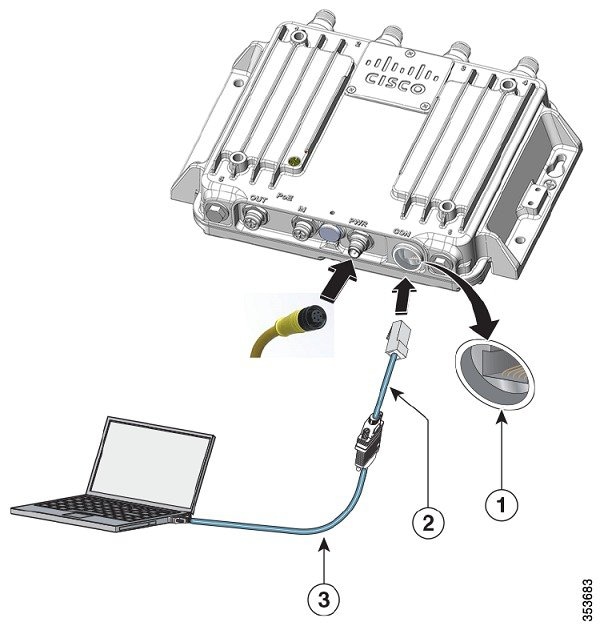
|
||||||
|
Step 4 |
Set up a terminal emulator (for example, puTTy or SSH) on your PC to communicate with the access point, using the following connection settings:
|
||||||
|
Step 5 |
When connected, press enter or type en to access the command prompt. Entering en prompts you for a password, and then enters privileged exec mode. The default password is Cisco and is case-sensitive. When you finish configuring the access point: |
||||||
|
Step 6 |
Use a small flat-blade screwdriver to depress the tab on the RJ45 connector and disconnect the cable from the CON port. |
||||||
|
Step 7 |
Replace the CON port cover. |
||||||
|
Step 8 |
Use a 0.5 in. (13 mm) socket wrench to torque the CON port cover to 6-7 ft-lbs (8.13-9.49 N-m).
|
Setting Access Point Settings
Use the system management pages in the web browser interface to set the access point settings. For information on how to access the web browser interface, see Configuring the Access Point for Autonomous Operation.
Use the system management pages to define configuration settings. A navigation bar appears on the left side of the page; the configuration action buttons appear at the bottom. Use the navigation bar to access the various management pages. Use the configuration action buttons to save or cancel setting changes.
Configuring the Access Point for Autonomous Operation
For information about configuring the access point for autonomous operations, see the Cisco IOS Configuration Guide for Autonomous Aironet Access Points.
Connecting the Access Point to a Wireless LAN Controller
This section describes how to connect the access point to a wireless LAN controller. Because the configuration process occurs on the controller, see the Cisco Wireless LAN Controller Configuration Guide for additional information.
The Controller Discovery Process
The access point uses standard Control and Provisioning of Wireless Access Points Protocol (CAPWAP) to communicate between the controller and other wireless access points on the network. CAPWAP is a standard, interoperable protocol that allows an access controller to manage a collection of wireless termination points. The discovery process using CAPWAP is identical to the Lightweight Access Point Protocol (LWAPP) used with Cisco IW3702 access points. LWAPP-enabled access points are compatible with CAPWAP, and conversion to a CAPWAP controller is seamless. Deployments can combine CAPWAP and LWAPP software on the controllers.
The functionality provided by the controller does not change, except for customers who have Layer 2 deployments, which CAPWAP does not support.
In a CAPWAP environment, the wireless access point discovers a controller by using CAPWAP discovery mechanisms and then sends it a CAPWAP join request. The controller sends the access point a CAPWAP join response to allow the access point to join the controller. When the access point joins the controller, the controller manages its configuration, firmware, control transactions, and data transactions.
For additional information about the discovery process and CAPWAP, see the Cisco Wireless LAN Controller Software Configuration Guide .
Note |
Refer to the Release Notes for the minimum required Cisco Wireless LAN Controller software release for the Cisco IW3702 access points. |
-
You cannot edit or query any access point using the controller CLI if the name of the access point contains a space.
-
Ensure that the controller is set to the current time. If the controller is set to a time that has already occurred, the access point might not join the controller because its certificate may not yet be valid.
Access points must be discovered by a controller before they can become active in the network. The access point supports these controller discovery processes:
-
Layer 3 CAPWAP discovery—Can occur on different subnets than the access point and uses IP addresses and UDP packets rather than MAC addresses used by Layer 2 discovery.
-
Locally stored controller IP address discovery—If the access point was previously joined to a controller, the IP addresses of the primary, secondary, and tertiary controllers are stored in the access point’s non-volatile memory. This process of storing controller IP addresses on an access point for later deployment is called priming the access point . See Performing a Pre-Installation Configuration.
-
DHCP server discovery—This feature uses DHCP option 43 to provide controller IP addresses to access points. Cisco switches support a DHCP server option that is typically used for this capability. See Configuring DHCP Option 43 and DHCP Option 60.
-
DNS discovery—The access point can discover controllers through your domain name server (DNS). To use this discovery method, you must configure the DNS to return controller IP addresses in response to CISCO-CAPWAP-CONTROLLER.localdomain , where localdomain is the access point domain name. Configuring the CISCO-CAPWAP-CONTROLLER provides backward compatibility in an existing deployment. When an access point receives the IP address and DNS information from a DHCP server, it contacts the DNS to resolve CISCO-CAPWAP-CONTROLLER.localdomain. When the DNS sends a list of controller IP addresses, the access point sends discovery requests to the controllers.
Performing a Pre-Installation Configuration
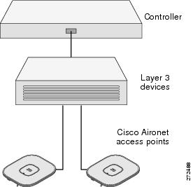
The following procedures ensure a successful access point installation and initial operational setup. Pre-installation configuration – priming the access point – is optional.
Note |
If your network controller already properly configured, you can skip priming and simply install your access point in its final location and connect it to the network. See Deploying in a Wireless Network. |
The following figure shows the pre-installation configuration setup.
To prime the access point:
SUMMARY STEPS
- Ensure that the Cisco Wireless LAN Controller Management DS Port is connected to the network. Use the CLI, browser-based interface, or Cisco WCS procedures described in the appropriate Cisco Wireless LAN Controller guide to perform the following:
- Apply power to the access point:
- (Optional) Configure the access point.
- Disconnect the access point and mount it in location.
DETAILED STEPS
|
Step 1 |
Ensure that the Cisco Wireless LAN Controller Management DS Port is connected to the network. Use the CLI, browser-based interface, or Cisco WCS procedures described in the appropriate Cisco Wireless LAN Controller guide to perform the following: |
||||
|
Step 2 |
Apply power to the access point: The access point is IEEE 802.3at (30 W) compliant and can be powered by a third-party DC power supply that you provide. The Cisco power injector option is AIR-PWRINJ1500-2=.
As the access point attempts to connect to the controller, the LEDs cycle through a green-red-amber sequence, which can take up to 5 minutes.
After a successful connection, the access point compares operating system code versions with the Cisco Wireless LAN Controller. If versions differ, it downloads the newest version. The Status LED blinks dark blue during this process. On a successful download, the access point reboots. |
||||
|
Step 3 |
(Optional) Configure the access point. Use the controller CLI, controller GUI, or Cisco Prime Infrastructure to customize access-point-specific IEEE 802.11ac network settings. On successful access point priming, the Status LED is green indicating normal operation. |
||||
|
Step 4 |
Disconnect the access point and mount it in location.
|
Using DHCP Option 43
You can use DHCP Option 43 to provide a list of controller IP addresses to the access points, enabling them to find and join a controller. For additional information, refer to Configuring DHCP Option 43 and DHCP Option 60.
Configuring DHCP Option 43 and DHCP Option 60
This section contains a DHCP Option 43 configuration example on a Windows 2003 Enterprise DHCP server for use with Cisco wireless access points. For other DHCP server implementations, consult the product documentation for configuring DHCP Option 43.
With DHCP Option 43, use the IP address of the controller management interface.
|
Notes: |
If you ordered an access point with the Service Provider Option (AIR-OPT60-DHCP) selected in the ordering tool, the VCI string for the access point contains -ServiceProvider . For example, an access point with this option returns this VCI string: |
The Cisco IW3702 access point uses the type-length-value (TLV) format for DHCP Option 43. The TLV block format is:
-
Type: 0xf1 (decimal 241)
-
Length: Number of controller IP addresses * 4
-
Value: List of Cisco Wireless LAN Controller management interfaces
To configure DHCP Option 43 in the embedded Cisco IOS DHCP server:
SUMMARY STEPS
- Enter configuration mode at the Cisco IOS CLI.
- Create the DHCP pool, including the necessary parameters such as default router and name server.
- Add the option 60 line using the following syntax:
- Add the option 43 line using the following syntax:
DETAILED STEPS
|
Step 1 |
Enter configuration mode at the Cisco IOS CLI. |
||
|
Step 2 |
Create the DHCP pool, including the necessary parameters such as default router and name server. Example DHCP scope commands: Example:where,
|
||
|
Step 3 |
Add the option 60 line using the following syntax: Example:where,
|
||
|
Step 4 |
Add the option 43 line using the following syntax: Example:The hex string is assembled by concatenating the TLV values: Type + Length + Value where,
TLV Example For two controllers with management interface IP addresses 10.126.126.2 and 10.127.127.2
The resultant IP addresses translate to 0a7e7e02 and 0a7f7f02. Assembling the string yields f1080a7e7e020a7f7f02. The resulting Cisco IOS command added to the DHCP scope is option 43 hex f1080a7e7e020a7f7f02. |
Deploying in a Wireless Network
To deploy the access point in a wireless network:
SUMMARY STEPS
- Connect and power up the access point.
- Observe the Status LED (see Status LED).
- Reconfigure the Cisco Wireless LAN Controller so that it is not the master .
DETAILED STEPS
|
Step 1 |
Connect and power up the access point. |
||
|
Step 2 |
Observe the Status LED (see Status LED). On successful power-up, the discovery and join process begins. During this process, the Status LED blinks green-red-off. On a successful join, the Status LED is green when no clients are associated, or blue when one or more clients are associated.
|
||
|
Step 3 |
Reconfigure the Cisco Wireless LAN Controller so that it is not the master . |
Configuring PoE Out Function
You can configure the PoE-Out port power function in autonomous mode for by using the following CLIs:
-
To disable the PSE function, use the power out-never command.
-
To turn on the PoE out function, use the no power out-never command.
ap(config)# power [inline | out-never]
  inline     Inline power configuration
  out-never  Never apply PoE out power
Note |
This command will not be effective if the AP is powered only by PoE/PoE+. |
Connecting Ethernet Daisy Chain
The Ethernet daisy chain feature is available on IW3702 autonomous mode.
IW3702 has two Ethernet ports: POE-IN (Gig0) and POE-OUT (Gig1). You can connect several IW3702 access points in daisy chain via Ethernet cables.
Note |
Make sure that you use 4-pair cables which support 1000 Mbps. This feature cannot work properly with 2-pair cables which support 100 Mbps. For the speed and duplex settings on the Ethernet port of the access point, it is recommended that you configure auto for both, which is the default setting. |
In daisy chain topology, each IW3702 can be powered either by DC input (through PWR connector) or POE inline (through POE IN port), but not both. To avoid inadvertently powering by dual sources, when connecting IW3702 to a device capable of PoE power sourcing (PSE, including another IW3702), see the following requirements:
-
Connection between two IW3702 access points:
-
POE-IN to POE-IN connection
-
POE-OUT to POE-OUT connection
-
-
Connection between other PSE (POE source) and IW3702:
-
Connect PSE to the POE-OUT port of IW3702
-
Connect non-PSE device to the POE-IN port of IW3702
-
Daisy Chain Connection Topologies
You can use the following connections for daisy chain topology:
-
Both IW3702-1 and IW3702-2 are powered by DC power source, with POE-IN to POE-IN connection between IW3702s. Make sure to configure power out-never on each IW3702 to disable the POE-OUT function.
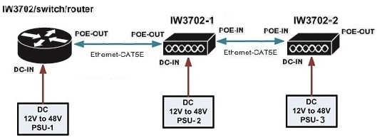
-
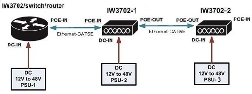
Both IW3702-1 and IW3702-2 are powered by DC power source, with POE-OUT to POE-OUT connection between IW3702s. Make sure to configure power out-never on each IW3702 to disable the POE-OUT function.
-
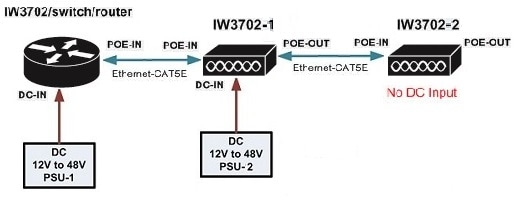
IW3702-1 is powered by DC power source, and IW3702-2 has no DC input. IW3702-2 can be powered on only when the POE-OUT port of IW3702-1 connects to the POE-IN port of IW3702.
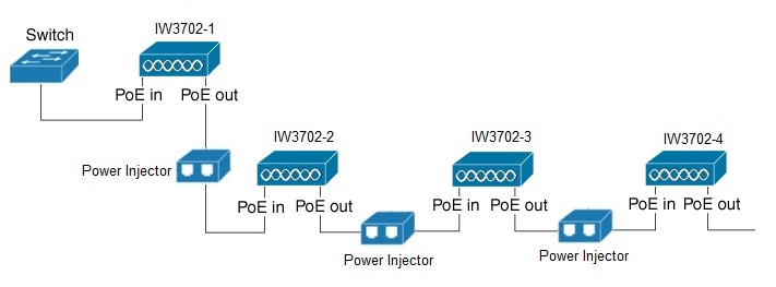
RAP Ethernet Daisy Chain on IW3702
The RAP Ethernet Daisy Chain feature is supported on Cisco Wireless LAN Controller Release 8.10.105.0.
In the daisy chain topology, if the link between RAP1 and RAP2 is broken, or RAP1 loses CAPWAP connectivity to the controller or switch, RAP2 will change its backhaul to wireless link. The Ethernet interfaces of RAP2 will be blocked and no child mesh AP will be allowed. Then, RAP3 and RAP4 will lose connection if they are far away from RAP1.
For the access point joining over wireless backhaul, it stays on wireless backhaul for 15 minutes and comes back to scan state every 15 minutes, until it finds a wired backhaul and joins the controller.
If the link between RAP1 and RAP2 is recovered, it takes up to 15 minutes for RAP2 to detect it and change back to Ethernet backhaul. Similarly, RAP3 and RAP4 will take additional time (maximum of 15 minutes at each hop) if they have joined over wireless backhaul.
The RAP Ethernet Daisy Chain feature enhances the existing Ethernet bridging functionality by introducing a new command to configure strict wired uplink on each access point. It forces the bridge AP to stick to the Ethernet link, and block the selecting of wireless link for uplink backhaul. Even the Ethernet link failure happens, the access point will never select a parent over wireless backhaul.
Note |
To support this Ethernet daisy chain topology, you MUST use power injector as the power supply for the access point. Supported power injectors are: AIR-PWRINJ1500-2=, AIR-PWRINJ-60RGD1=, and AIR-PWRINJ-60RGD2=. |
If there is a CAPWAP loss on the first access point (RAP1) connected to switch, the entire chain will lose uplink. It takes about 15 seconds for each access point to recovery the CAPWAP connection after the upstream RAP1 is recovered. The last RAP in N hop chain takes maximum 15xN seconds to recover the connection.
You can configure strict wired uplink only if the AP is configured as Bridge or Flex Bridge mode, Root AP role, and connected to WLC using wired connection. If it connects to WLC using radio link, the configuration is not allowed.
Note |
After the configuration, the AP may be in MAP role. It is required to prime all AP to RAP role before connecting all of them with the wired connection. Otherwise there may be loop issues if MAP uses wireless backhaul to connect to the other AP. |
WLC Configuration for RAP Ethernet Daisy Chain
Procedure
|
Step 1 |
Configure the AP in bridge/flex bridge mode. CLI: GUI: wireless -> All APs -> Details (General) page -> AP mode 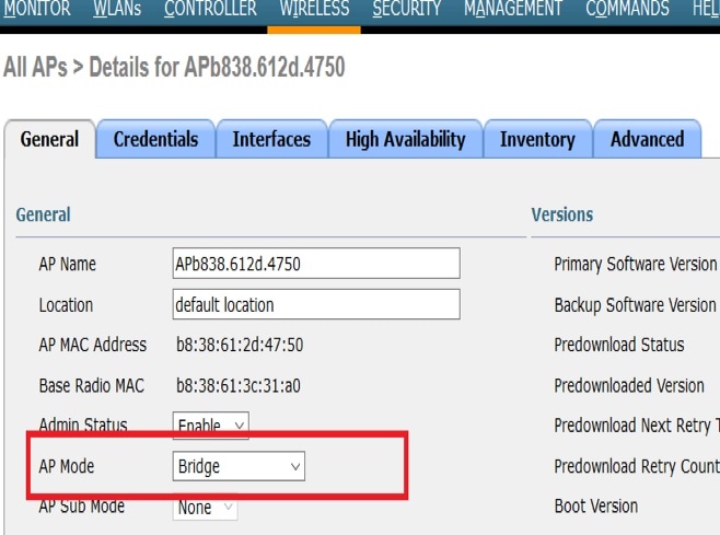
For more details, refer to: https://www.cisco.com/c/en/us/td/docs/wireless/controller/technotes/8-7/b_mesh_87/b_mesh_87_chapter_0110.html#ID4755 |
||
|
Step 2 |
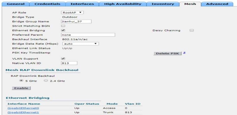
Change the AP role to Root. CLI: GUI: Wireless -> All APs -> Details (Mesh) page -> AP role 
|
||
|
Step 3 |
Enable Ethernet interface 1 for all the APs from the controller. CLI: |
||
|
Step 4 |
Configure Ethernet bridging. Ethernet bridging must be enabled on all APs in the Bridge mode.
CLI: GUI: Wireless > Access Point > (AP_NAME) > Mesh, and then check the Ethernet bridging check box 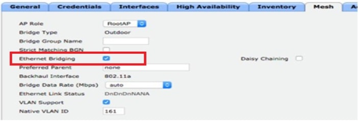
For more details, refer to the Connecting the Cisco 1500 Series Mesh Access Points to the Network chapter of the Cisco Wireless Mesh Access Points, Design and Deployment Guide. |
||
|
Step 5 |
Configure Strict Wired Uplink Use the following command to enabled or disable strict wired uplink on a specific AP: CLI: |
||
|
Step 6 |
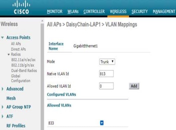
(Optional) For Multiple VLAN deployment, follow step 6 to 8. Disable VLAN transparency from the controller. CLI: GUI: Wireless--> Mesh ---> Ethernet Bridging 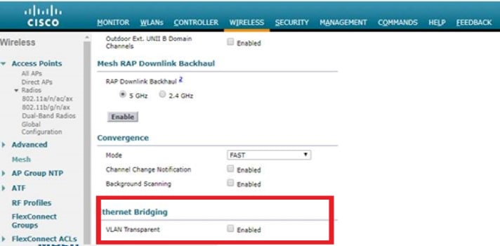
|
||
|
Step 7 |
If Multiple VLANs are used with one native VLAN and other as allowed VLAN, verify VLAN support is enabled in each RAP. CLI:
GUI:

|
||
|
Step 8 |
Configure the Ethernet interface of each RAP with native VLAN and add the other allowed VLAN. CLI:
GUI:
|
Verifying the Configuration
Use the following command to display the feature state for AP:
(Cisco Controller) >show ap config general <Cisco_AP>
AP Mode ......................................... Bridge
AP Role ......................................... RootAP
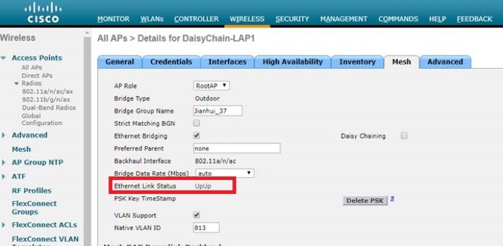
Ethernet Bridging ............................... Enabled
Strict Wired Uplink ............................. Enabled
Use the following command to ensure whether the admin status and line protocol of the Ethernet interfaces 0/1 are up.
AP#show interfaces gigabitEthernet 0
GigabitEthernet0 is up, line protocol is up
  Hardware is PowerPC Ethernet, address is 2cd0.2de8.ab80 (bia 2cd0.2de8.ab80)
  MTU 1500 bytes, BW 1000000 Kbit/sec, DLY 10 usec,
     reliability 255/255, txload 1/255, rxload 1/255
  Encapsulation 802.1Q Virtual LAN, Vlan ID  1., loopback not set
  Keepalive set (10 sec)
  Full Duplex, 1Gbps, media type is T
  output flow-control is unsupported, input flow-control is unsupported
  ARP type: ARPA, ARP Timeout 04:00:00
  Last input 00:00:00, output never, output hang never
  Last clearing of "show interface" counters never
  Input queue: 2/42878/649/0 (size/max/drops/flushes); Total output drops: 0
  Queueing strategy: fifo
WLC GUI: Wireless --> AP --> Mesh --> Ethernet link Status
Use the following command to display the feature status for all bridge RAP:
(Cisco Controller) >show mesh strict-wired-uplink summary
AP Name      AP Model             BVI MAC          Role  Bridge Group Name   Strict Wired Uplink
--------  -------------------  -----------------   ----  -----------------  --------------------
IW1       IW3702-2E-A-K9       00:a2:ee:59:4b:c0   RAP   Qia_37             Enable
IW37-3    IW3702-4E-A-K9       2c:d0:2d:e8:ab:80   RAP   Qia_37             Enable

Number of Mesh RAP Strict Wired Uplink Set....... 2
Use the following command to display strict wired uplink status on the access point:
Daisychain-AP#show mesh status
 show MESH Status
 RootAP in state Maint
 Uplink Backbone: GigabitEthernet0,  hw GigabitEthernet0
 Configured BGN: DSAP3702, Extended mode 0
 Children: Accept child
 No.of Children: 0
 Strict Wired Uplink: Enable
Configuration Guidelines
Note |
To make sure this feature works properly, the power injector MUST be used as power supply for the AP. |
-
Ethernet bridging on all RAPs in the chain should be enabled and secondary Ethernet interfaces needs to be configured according to the mesh deployment guidelines.
-
Strict wired uplink configuration needs to be done on each AP in order to enable this feature.
-
Strict wired uplink configuration is supported only on IOS-based IW3702 Access Points and applicable only when the AP is operating in Bridge or Flex Bridge mode in Root AP role.
-
For Flex bridge mode, if it is local switching WLAN, WGB multiple VLAN is not supported.
-
If this feature is enabled, the AP will keep scanning until at least one Ethernet adjacency is found. The Ethernet link will not be added to blacklist and continue being used as backhaul.
-
All the traffic will go through the RAP1 which is a bottleneck and the total network throughput is limited. There should be around 10% bandwidth reserved for CAPWAP management traffic in high traffic load case.
-
Make sure that you use 4-pair cables which support 1000 Mbps. This feature cannot work properly with 2-pair cables which support 100 Mbps.
-
Follow the Ethernet chaining guideline in the Connecting Ethernet Daisy Chain section to establish cable connections.
-
Connecting one IW3702’s G0 interface to another IW3702’s G1 interface directly may cause issues in the AP’s POE function and may damage the AP. To support this feature, the power injector MUST be used as power supply for the AP.
Deployment Option 1
Procedure
|
Step 1 |
Connect the mesh AP to WLC through wired connection. |
|
Step 2 |
Prime all APs to RAP role on the daisy chain topology. |
|
Step 3 |
Configure config ap bridging enable <Cisco_AP > to enable Ethernet bridging. This command allows the next AP to connect on its Secondary Ethernet interface. |
|
Step 4 |
Configure config ap strict-wired-uplink enable <Cisco_AP > to enable the feature. At this time, the AP can only connect to WLC through a wired connection. |
|
Step 5 |
Connect all APs using wired daisy chain topology. |
Deployment Option 2
Procedure
|
Step 1 |
Connect all the APs using wired daisy chain topology. Make sure all APs are powered off. |
|
Step 2 |
Power on the first AP which is closest to the switch or WLC. Make sure it can connect to WLC through a wired connection. |
|
Step 3 |
Set the AP role to RAP. |
|
Step 4 |
Configure config ap bridging enable <Cisco_AP > to enable Ethernet bridging. This command allows the next AP to connect on its Secondary Ethernet interface. |
|
Step 5 |
Configure config ap strict-wired-uplink enable <Cisco_AP > to enable the feature. At this time, the AP can only connect to WLC through a wired connection. |
|
Step 6 |
Power on the AP which is next to the previous AP. |
|
Step 7 |
Repeat Step3 to Step 5. |
Troubleshoot Guidelines
Debug to be enabled on AP:
-
debug capwap client event
-
debug capwap client payload—To ensure that strict-wired-uplink config payload from WLC to AP
-
debug mesh ethernet bridging—Debugs Ethernet bridging
Show commands on AP:
#show interfaces gigabitEthernet 0
GigabitEthernet0 is up, line protocol is up
  Hardware is PowerPC Ethernet, address is 2cd0.2de8.ab80 (bia 2cd0.2de8.ab80)
  MTU 1500 bytes, BW 1000000 Kbit/sec, DLY 10 usec,
     reliability 255/255, txload 1/255, rxload 1/255
  Encapsulation 802.1Q Virtual LAN, Vlan ID  1., loopback not set
  Keepalive set (10 sec)
  Full Duplex, 1Gbps, media type is T
  output flow-control is unsupported, input flow-control is unsupported
  ARP type: ARPA, ARP Timeout 04:00:00
  Last input 00:00:00, output never, output hang never
  Last clearing of "show interface" counters never
  Input queue: 2/42878/649/0 (size/max/drops/flushes); Total output drops: 0
  Queueing strategy: fifo
  Output queue: 0/40 (size/max)
  5 minute input rate 1000 bits/sec, 2 packets/sec
  5 minute output rate 7000 bits/sec, 3 packets/sec
     3382115 packets input, 390507998 bytes, 0 no buffer
     Received 1812139 broadcasts (0 IP multicasts)
     0 runts, 0 giants, 0 throttles
     0 input errors, 0 CRC, 0 frame, 0 overrun, 0 ignored
     0 watchdog, 0 multicast, 0 pause input
     4807536 packets output, 1258122159 bytes, 0 underruns
     0 output errors, 0 collisions, 4 interface resets
     0 unknown protocol drops
     0 babbles, 0 late collision, 0 deferred
     0 lost carrier, 0 no carrier, 0 pause output
     0 output buffer failures, 0 output buffers swapped out

#show capwap client rcb
AdminState                  :  ADMIN_ENABLED
Primary SwVer               :  8.10.118.37
Backup  SwVer               :  0.0.0.0
NumFilledSlots              :  2
Name                        :  AP00ee.abe3.6240
Location                    :  default location
MwarName                    :  Cisco-cc70.ed03.d3b2
MwarApMgrIp                 :  10.100.60.150
MwarHwVer                   :  0.0.0.0
ApMode             :  Bridge
ApSubMode                   :  Not Configured
OperationState              :  UP
CAPWAP Path MTU             :  1485
Link-Encryption (AP)        :  Disabled
Link-Encryption (MWAR)      :  Enabled
Prefer-mode                 :  IPv4
LinkAuditing                :  disabled
ApRole             :  RootAP
ApBackhaul                  :  802.11a
ApBackhaulChannel           :  0
ApBackhaulSlot              :  3
ApBackhaul11gEnabled        :  0
ApBackhaulTxRate            :  0
Ethernet Bridging State     :  1
Daisy Chaining State        :  Enabled
Public Safety State         :  disabled
AP Rogue Detection Mode     :  Enabled
AP Tcp MSS Adjust           :  Enabled
AP Tcp MSS size             :  1250
Predownload Status          :  None
Auto Immune Status          :  Disabled
RA Guard Status             :  Enabled
Efficient Upgrade State     :  Disabled
Efficient Upgrade Role      :  None
Antenna Band Mode           :  Dual Band
Universal AP Priming mode   :  Unprimed
802.11bg(0) Radio
ADMIN  State = DISABLE [2]
OPER   State =    DOWN [1]
CONFIG State =    DOWN [1]
HW     State =    DOWN [6]
Radio Mode                : Bridge
GPR Period                : 10
Beacon Period             : 100
DTIM Period               : 0
World Mode                : 1
VoceraFix                 : 0
Dfs peakdetect            : 0
Fragmentation Threshold   : 2346
Current Tx Power Level    : 1
Current Channel           : 1
Current Bandwidth         : 20
802.11a(1) Radio
ADMIN  State =  ENABLE [1]
OPER   State =      UP [2]
CONFIG State =      UP [2]
HW     State =      UP [4]
Radio Mode                : Bridge
GPR Period                : 10
Beacon Period             : 100
DTIM Period               : 0
World Mode                : 1
VoceraFix                 : 0
Dfs peakdetect            : 1
Fragmentation Threshold   : 2346
Current Tx Power Level    : 1
Current Channel           : 36
Current Bandwidth         : 20
Nexthop MAC Address         :  cc70.ed03.d3b8
HYPERLOCATION ADMIN STATE      : 0
WLC GATEWAY MAC               : 00:00:00:00:00:00
WLC HYPERLOCATION SRC PORT    : 0
Remote Machine's IP  : 0.0.0.0

#show mesh status
 RootAP in state Scan
No active links
 Configured BGN: , Extended mode 0
 Children: Not accept child
 No.of Children: 0
        rxNeighReq 0 rxNeighRsp 0 txNeighReq 0 txNeighRsp 0
        rxNeighRsp 211 txNeighUpd 0
        nextchan 0 nextant 0 downAnt 0 downChan 0 curAnts 0
        nextNeigh 0, malformedNeighPackets 0,poorNeighSnr 0
        excludedPackets 0,insufficientMemory 0, authenticationFailures 0
        Parent Changes 0, Neighbor Timeouts 0
        Auto Parent Switch 0

        Authentication Failure statistics
        Child MAC                 No.Of PSK Failures
Preferred Parent 0000.0000.0000
Block Child Status: Disable
Strict Wired Uplink: Disable
show mesh module adjacency
show mesh ethernet vlan config running

#show mesh module mesh-control
mesh lwapp module
skip cleanup: Not set
join timer: Set
boot timer: Set
capwap dhcp: Set
standalone: Not set
was standalone: Not set
abort standalone: Not set
joined once: Set

Mesh Capwap State: JOINED-UP

Lwapp link 00ee.abe3.6241

#show mesh forwarding interfaces
  GigabitEthernet0: GigabitEthernet0(state is OPEN)
  GigabitEthernet1: GigabitEthernet1(state is OPEN)
      Node 00ee.abe3.6241
  GigabitEthernet2: GigabitEthernet2(state is OPEN)
  GigabitEthernet3: GigabitEthernet3(state is OPEN)
  GigabitEthernet4: GigabitEthernet4(state is OPEN)

#show mesh ethernet vlan config running
 Running Ethernet VLAN Configuration

Ethernet Interface: 0  mode: TRUNK Native Vlan: 1
 Vlans: 4095
Ethernet Interface: 1  mode: TRUNK Native Vlan: 1
 Vlans: 4095
Ethernet Interface: 2  mode: TRUNK Native Vlan: 1
 Vlans: 4095
Ethernet Interface: 3  mode: TRUNK Native Vlan: 1
 Vlans: 4095
Ethernet Interface: 4  mode: TRUNK Native Vlan: 1
 Vlans: 4095

VLAN - root hwidb:GigabitEthernet1 global BVI:NULL

          VlanID   BrgGrp   Type    Routed   Active
        ---------------------------------------------


GigabitEthernet0 enabled: 1, active: 0, etherbridge 1, line-p: 0, state-up: 1
GigabitEthernet1 enabled: 1, active: 0, etherbridge 1, line-p: 1, state-up: 1
GigabitEthernet2 enabled: 1, active: 0, etherbridge 1, line-p: 0, state-up: 1
GigabitEthernet3 enabled: 1, active: 0, etherbridge 1, line-p: 0, state-up: 1
GigabitEthernet4 enabled: 1, active: 0, etherbridge 1, line-p: 0, state-up: 1
For more details on troubleshoot, refer to: https://www.cisco.com/c/en/us/td/docs/wireless/controller/8-3/config-guide/b_cg83/troubleshooting_mesh_access_points.html#ID9205
Configuring Indoor Support for Q Domain Models
Both indoor and outdoor use are supported for IW3702 Q domain models, for unified mode and autonomous mode. By default, outdoor mode is enable, and channel 36-64 are disabled. After enabling indoor support on the access point, channel 36-64 will be open for indoor use.
Note |
After factory reset, the indoor mode will be changed back to default outdoor mode. |
Enabling Indoor Support for Unified Mode AP
In WLC, use the following command to configure IW3702 in unified mode for indoor support:
(Cisco Controller)> config ap indoor {enable|disable} <AP-Name>
Example:
(Cisco Controller)> config ap indoor enable AP3
Changing the AP's indoor mode will cause the AP to reboot.
Are you sure you want to continue? (y/n) y
Use the following command to check the current mode of AP:
show ap env <AP-Name>
Example:
show ap env AP3
AP Name.......................................... AP3
AP Model......................................... IW3702-4E-Q-K9
AP Role.......................................... Normal

Temperature...................................... N/A
Backhaul......................................... N/A
Indoor Mode...................................... True

GigabitEthernet0 Status.......................... UP
    Duplex....................................... FULL
    Speed........................................ 1000
    Rx Unicast Packets........................... 13148
    Rx Non-Unicast Packets....................... 72406
    Tx Unicast Packets........................... 18423
    Tx Non-Unicast Packets....................... 4420
GigabitEthernet1 Status.......................... DOWN

Battery.......................................... N/A
Enabling Indoor Support for Autonomous Mode AP
Use the following command to configure indoor support for autonomous AP:
ap(config)# dot11 indoor {enable|disable}
Example:
ap(config)# dot11 indoor enable
Enable AP indoor support in the "Q" Regulatory Domain.
WARNING: The configed AP will reboot.

Begin to enable AP indoor support. Do you want to Continue ? (yes/[no]): yes
Use the following command to display the current status of indoor support:
show dot11 indoor
Configuring Heaters
There are two heaters for each IW3702 access point. By default, they are enabled and will start to work when the environment tempreature is under -20°C. If you determine that the environment tempreature where the IW3702 is deployed will never be under -20°C, you can turn off the heaters, which allows the IW3702 to request less power from the switch when the IW3702 is powered by PoE+.
Note |
You must be cautious to turn off the heaters. If the temperature is under -20°C while the heaters are turned off, IW3702 will not work properly, which might cause damage to the AP. |
Note |
Two heaters will be disabled or enabled together. |
Use the following command to enable or disable the heaters:
(config)#heater  {disable |enable }
  disable Disable AP heater
  enable  Enable AP heater
Note |
By default, the heaters are enabled. The execution of the heater enable or disable command will trigger the AP reload. |
-
If the heaters are disabled, AP requests maximum power of 21w. The heaters will never start to work even the environment tempreature is under -20°C.
-
If the heaters are enabled, AP requests maximum power of 30w. The heaters will be turned on automatically when the environment tempreature is under -20°C.
Use the following command to display the current status of the heaters:
#show heater_status
MCU Firmware Version = 7
Heater1 - OFF, Heater2 – OFF
Heaters admin disabled
Technical Specifications
This section provides the following technical specifications for the access point:
Environmental and Operational Specifications
|
Description |
Specification |
|---|---|
|
Operating temperature |
–40 to 158°F (–40 to +70°C) with solar load and still air |
|
Altitude |
15,000 ft. (4.5 m) |
|
Humidity |
5 to 95% (non-condensing) |
|
Extended operating temperature (DC power) |
–58 to 167°F (–50 to +75°C) without solar loading, still air, and cold start limited to –40°C |
|
Operating type test |
185°F (85°C) for 16 hours |
|
Storage temperature |
–40 to 185°F (–40 to +85°C) |
|
Vibration |
Per IEEE 1613, IEC 61850, EN50155, and AREMA |
|
Shock |
Per IEEE 1613, IEC 61850, EN50155, and AREMA |
|
Seismic |
Per IEC 61850-3 Class 2 |
Power Specifications
Power Requirements
|
Power Input Type |
Environment Condition/Heaters |
Wi-Fi Radio Mode |
PoE Out |
Power Budget (Watts) |
|---|---|---|---|---|
|
PoE 802.3af |
> -20°C No heaters active |
3x3:3 on 2.4/5 GHz |
N/A |
15.4 |
|
PoE+ 802.3at |
> -20°C No heaters active |
4x4:3 on 2.4/5 GHz |
N/A |
21 |
|
PoE+ 802.3at |
-50°C to -20°C Still air 1 heater active |
4x4:3 on 2.4/5 GHz |
N/A |
30 |
|
DC In |
> -20°C No heaters active |
4x4:3 on 2.4/5 GHz |
No |
20 |
|
DC In |
-50°C to -20°C Still air 1 heater active |
4x4:3 on 2.4/5 GHz |
No |
37 |
|
DC In |
-50°C to -20°C Wind cooling 2 heaters active |
4x4:3 on 2.4/5 GHz |
No |
53 |
|
DC In |
> -20°C No heaters active |
4x4:3 on 2.4/5 GHz |
Yes |
38 |
|
DC In |
-50°C to -20°C Still air 1 heater active |
4x4:3 on 2.4/5 GHz |
Yes |
55 |
|
DC In |
-50°C to -20°C Wind cooling 2 heaters active |
4x4:3 on 2.4/5 GHz |
Yes |
71 |
DC Input and PoE IN Specifications
The access point supports two power options:
-
DC input from the PWR connector.
-
PoE inline power from the PoE IN port.
Note |
The PoE OUT port is enabled only when the access point is powered over the PWR port. When powered over the PoE IN port, PoE OUT functionality is not supported. |
In relation to powering the access point:
-
Power can be supplied by the DC input (PWR port connection) or the PoE inline power (PoE IN port), but not both.
-
We recommend not using the two power options at the same time, but no harm results if both are present.
-
If both power inputs are present, the DC input (PWR port connection) takes precedence and PoE IN becomes idle and unused.
-
Power supply redundancy is not supported.
Supported Power Adapters
The following table shows the power adapters supported for the Cisco IW3702 access point.
|
PID |
Description |
|---|---|
|
AIR-PWRADPT3700NA= |
AC to DC power adapter, with North American plug |
|
AIR-PWRADPT3700IN= |
AC to DC power adapter, international version without AC plug |
Supported PoE Power Injectors
The following power injectors are supported for the Cisco IW3702 access point:
-
AIR-PWRINJ1500-2=: PoE+ power injector, for indoor environments
Note
The power injector AIR-PWRINJ1500-2= is not IP rated for outdoors. Use it in an indoor environment only or put it in an NEMA enclosure. For more information, see Cisco Aironet Series Power Injector AIR-PWRINJ1500-2= Installation Instructions.
-
AIR-PWRINJ-60RGD1=: PoE+ power injector, for outdoor environments, with North American plug
-
AIR-PWRINJ-60RGD2=: PoE+ power injector, for outdoor environments, international version without AC plug
Note
The power injectors AIR-PWRINJ-60RGD1= and AIR-PWRINJ-60RGD2= are IP66 rated. It does not meet all industrial specifications as supported by the IW3702. For more information, see Cisco Aironet Series Power Injectors AIR-PWRINJ-60RGD1= and AIR-PWRINJ-60RGD2= Installation Instructions.
The following table lists specifications for the available power inputs.
|
Power INPUT |
WiFi 4 x 4 MIMO |
GE-POE-OUT (POE PSE) |
GE-POE-OUT (10/100/1000) |
Operating Temperature Range4 |
Wire Thickness, Min Rating |
Length (Max)5 |
|---|---|---|---|---|---|---|
|
DC Input at +12V |
Yes |
Yes, 802.3af |
Yes |
-58 to 167°F (-50 to 75°C) |
16 AWG, 8 A |
20'/6.1m |
|
DC Input at +24V |
Yes |
Yes, 802.3af |
Yes |
-58 to 167°F (-50 to 75°C) |
20 AWG, 4 A |
30'/9.1m |
|
DC Input at +48V |
Yes |
Yes, 802.3af |
Yes |
-58 to 167°F (-50 to 75°C) |
20 AWG, 2 A |
60'/18.3m |
|
POE-IN, 802.3at (POE+, 25W) |
Yes |
No |
Yes |
-40 to 167°F (-40 to 75°C) |
CAT5e(24AWG), 0.6 A, shielded |
100m |
|
POE-IN, 802.3af (POE, 13W) |
No(3x3 only) |
No |
No |
-4 to 167°F (-20 to 75°C) |
CAT5e(24AWG), 0.6 A, shielded |
100m |
Mechanical Specifications
|
Description |
Specification |
|---|---|
|
Enclosure type |
IP67 Type 4X |
|
Dimensions (h x w x d) |
|
|
Weight |
6.7 lbs. (3.0 kg) |
Regulatory Compliance and Safety Information
For information about the international regulatory compliance and safety information for the Cisco IW3702 access point, see the Regulatory Compliance and Safety Information for Cisco IW3702 Access Point on Cisco.com.
Declaration of Conformity for RF Exposure
This section contains information on compliance with guidelines related to RF exposure.
Generic Discussion on RF Exposure
The Cisco products are designed to comply with the following national and international standards on human exposure to radio frequencies:
-
US 47 Code of Federal Regulations Part 2 Subpart J
-
American National Standards Institute (ANSI) / Institute of Electrical and Electronic Engineers / IEEE C 95.1 (99)
-
International Commission on Non Ionizing Radiation Protection (ICNIRP) 98
-
Ministry of Health (Canada) Safety Code 6. Limits on Human exposure to radio frequency fields in the range from 3kHz to 300 GHz
-
Australia Radiation Protection Standard
To ensure compliance with various national and international Electromagnetic Field (EMF) standards, the system should only be operated with Cisco approved antennas and accessories.
Declaration of Conformity for RF Exposure (ANSI)
United States
This system has been evaluated for RF exposure for humans in reference to ANSI C 95.1 (American National Standards Institute) limits. The evaluation was based on ANSI C 95.1 and FCC OET Bulletin 65C rev 01.01. The minimum separation distance from the antenna to general bystanders is 9 inches (23 cm) to maintain compliance.
Canada
This system has been evaluated for RF exposure for humans in reference to ANSI C 95.1 (American National Standards Institute) limits. The evaluation was based on RSS-102 Rev 2. The minimum separation distance from the antenna to general bystanders is 9 inches (23cm) to maintain compliance.
This Device Meets International Guidelines for Exposure to Radio Waves (ICNIRP)
The Cisco IW3702 access point includes a radio transmitter and receiver. It is designed not to exceed the limits for exposure to radio waves (radio frequency electromagnetic fields) recommended by international guidelines. The guidelines were developed by an independent scientific organization (ICNIRP) and include a substantial safety margin designed to ensure the safety of all persons, regardless of age and health. As such, the systems are designed to be operated to avoid contact with the antennas by the end user.
It is recommended to place the system in a location where the antennas can remain the minimum distance from the user specified in the regulatory guidelines, which are designed to reduce the overall exposure of the user or operator.
|
Separation Distance |
||
|---|---|---|
|
MPE |
Distance |
Limit |
|
0.63 mW/cm2 |
7.87 in. (20 cm) |
1.00 mW/cm2 |
The World Health Organization has stated that present scientific information does not indicate the need for any special precautions for the use of wireless devices. They recommend that if you are interested in further reducing your exposure, you can easily orient antennas away from users or place the antennas at a greater separation distance than recommended.
This Device Meets FCC Guidelines for Exposure to Radio Waves
The Cisco IW3702 access point includes a radio transmitter and receiver. It is designed not to exceed the limits for exposure to radio waves (radio frequency electromagnetic fields) as referenced in FCC Part 1.1310. The guidelines are based on IEEE ANSI C 95.1 (92) and include a substantial safety margin designed to ensure the safety of all persons, regardless of age and health. As such, the systems are designed to be operated to avoid contact with the antennas by the end user. We recommend that you place the system in a location where antennas remain a minimum distance from the user in accordance to the regulatory guidelines, which are designed to reduce the overall exposure of the user or operator.
The device has been tested and found compliant with the applicable regulations as part of the radio certification process.
|
Separation Distance |
||
|---|---|---|
|
MPE |
Distance |
Limit |
|
0.63 mW/cm2 |
20 cm (7.87 inches) |
1.00 mW/cm2 |
The US Food and Drug Administration has stated that present scientific information does not indicate the need for any special precautions for the use of wireless devices. The FCC recommends that if you are interested in further reducing your exposure, you can easily orient antennas away from the user or place the antennas at a greater separation distance than recommended, or lower the transmitter power output.
This Device Meets the Industry Canada Guidelines for Exposure to Radio Waves
The Cisco IW3702 access point includes a radio transmitter and receiver. It is designed not to exceed the limits for exposure to radio waves (radio frequency electromagnetic fields) as referenced in Health Canada Safety Code 6. The guidelines include a substantial safety margin designed into the limit to ensure the safety of all persons, regardless of age and health. As such, the systems are designed to be operated to avoid contact with the antennas by the end user. We recommend that you place the system in a location where antennas remain a minimum distance from the user in accordance to the regulatory guidelines, which are designed to reduce the overall exposure of the user or operator.
|
Separation Distance |
||
|---|---|---|
|
MPE |
Distance |
Limit |
|
0.63 mW/cm2 |
20 cm (7.87 inches) |
1.00 mW/cm2 |
Health Canada states that present scientific information does not indicate the need for any special precautions for the use of wireless devices. They recommend that if you are interested in further reducing your exposure, you can easily orient antennas away from the user or place the antennas at a greater separation distance than recommended, or lower the transmitter power output.
Additional Information on RF Exposure
You can find additional information on the subject at the following links:
-
Cisco Systems Spread Spectrum Radios and RF Safety white paper
-
FCC Bulletin 56: Questions and Answers about Biological Effects and Potential Hazards of Radio Frequency Electromagnetic Fields
-
FCC Bulletin 65: Evaluating Compliance with the FCC guidelines for Human Exposure to Radio Frequency Electromagnetic Fields
-
FCC Bulletin 65C (01-01): Evaluating Compliance with the FCC guidelines for Human Exposure to Radio Frequency Electromagnetic Fields: Additional Information for Evaluating Compliance for Mobile and Portable Devices with FCC limits for Human Exposure to Radio Frequency Emission
You can obtain additional information from the following organizations:
-
World Health Organization Internal Commission on Non-Ionizing Radiation Protection
-
United Kingdom, National Radiological Protection Board
-
Cellular Telecommunications Association at this URL:
-
The Mobile & Wireless Forum at this URL:
Guidelines for Operating Cisco IW3702 Access Points in Japan
This section provides guidelines for avoiding interference when operating Cisco IW3702 access points in Japan. These guidelines are provided in both Japanese and English.
Japanese
English
This equipment operates in the same frequency bandwidth as industrial, scientific, and medical devices such as microwave ovens and mobile object identification (RF-ID) systems (licensed premises radio stations and unlicensed specified low-power radio stations) used in factory production lines.
-
Before using this equipment, ensure that no premises radio stations or specified low-power radio stations of RF-ID are in the vicinity.
-
If this equipment causes RF interference to a premises radio station of RF-ID, promptly change the frequency or stop using the device; call the number below and ask for recommendations on avoiding radio interference such as setting partitions.
-
If this equipment causes RF interference to a specified low-power radio station of RF-ID, call the number below. Contact Number: 03-6434-6500
Administrative Rules for Cisco IW3702 Access Points in Taiwan
This section provides administrative rules for operating Cisco IW3702 access points in Taiwan. The rules for all access points are provided in both Chinese and English.
Chinese Translation Part 1
English Translation Part 1
Administrative Rules for Low-power Radio-Frequency Devices
Article 12: For those low-power radio-frequency devices that have already received a type-approval, companies, business units or users should not change its frequencies, increase its power or change its original features and functions.
Article 14: The operation of the low-power radio-frequency devices is subject to the conditions that no harmful interference is caused to aviation safety and authorized radio station; and if interference is caused, the user must stop operating the device immediately and can't re-operate it until the harmful interference is clear.
The authorized radio station means a radio-communication service operating in accordance with the Communication Act.
The operation of the low-power radio-frequency devices is subject to the interference caused by the operation of an authorized radio station, by another intentional or unintentional radiator, by industrial, scientific and medical (ISM) equipment, or by an incidental radiator.
Chinese Translation Part 2
English Translation Part 2
Low-power Radio-frequency Devices Technical Specifications:
|
4.7 |
Unlicensed National Information Infrastructure |
|
4.7.5 |
Within the 5.25-5.35 GHz band, U-NII devices will be restricted to indoor operations to reduce any potential for harmful interference to co-channel MSS operations. |
|
4.7.6 |
The U-NII devices shall accept any interference from legal communications and shall not interfere the legal communications. If interference is caused, the user must stop operating the device immediately and can't re-operate it until the harmful interference is clear. |
|
4.7.7 |
Manufacturers of U-NII devices are responsible for ensuring frequency stability such that an emission is maintained within the band of operation under all conditions of normal operation as specified in the user manual. |
Operation of Cisco IW3702 Access Points in Brazil
This section contains information for operating Cisco IW3702 access points in Brazil.
Regulatory Information
Portuguese Translation
Este equipamento opera em caráter secundário, isto é, não tem direito a proteção contra interferência prejudicial, mesmo de estações do mesmo tipo, e não pode causar interferência a sistemas operando em caráter primário.
English Translation
This equipment operates on a secondary basis and consequently must accept harmful interference, including interference from stations of the same kind. This equipment may not cause harmful interference to systems operating on a primary basis.
Declaration of Conformity Statements
All the Declaration of Conformity statements related to this product can be found at the following location:
Ports and Connectors
The port pinouts and connector details are described in this section.
Power Port
The power port is a 4-pin M12 A-code male connector.
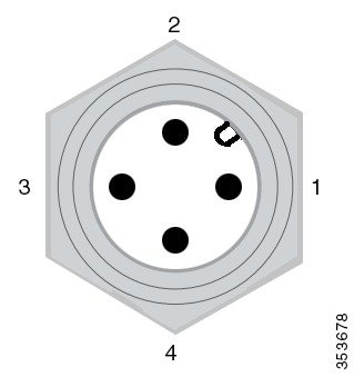
|
1 |
Positive DC power connection |
3 |
Negative DC power connection |
|
2 |
Positive DC power connection |
4 |
Negative DC power connection |
PoE OUT Port
The PoE OUT port is an 8-pin M12 X-code female connector.
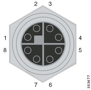
|
1 |
0_P signal |
5 |
3_P |
|
2 |
0_N signal |
6 |
3_N |
|
3 |
1_P signal |
7 |
2_N |
|
4 |
1_N signal |
8 |
2_P |
PoE IN Port
The PoE IN port is a 8-pin M12 X-code female connector.
|
1 |
0_P signal |
5 |
3_P |
|
2 |
0_N signal |
6 |
3_N |
|
3 |
1_P signal |
7 |
2_N |
|
4 |
1_N signal |
8 |
2_P |
Console Port
The console port is an RJ-45 connector.
|
Pin |
Signal |
|---|---|
|
1 |
RTS output |
|
2 |
DTR input |
|
3 |
TxD output |
|
4 |
GND |
|
5 |
GND |
|
6 |
RxD input |
|
7 |
DSR output |
|
8 |
CTS input |
Related Documentation
The following are other documents in the IW3700 Industrial Wireless Access Point Series:
Obtaining Documentation and Submitting a Service Request
For information on obtaining documentation, using the Cisco Bug Search Tool (BST), submitting a service request, and gathering additional information, see What’s New in Cisco Product Documentation .
To receive new and revised Cisco technical content directly to your desktop, you can subscribe to the What’s New in Cisco Product Documentation RSS feed . The RSS feeds are a free service.
 Feedback