Cisco Wireless Intrusion Prevention System Configuration Guide, Release 8.0
Bias-Free Language
The documentation set for this product strives to use bias-free language. For the purposes of this documentation set, bias-free is defined as language that does not imply discrimination based on age, disability, gender, racial identity, ethnic identity, sexual orientation, socioeconomic status, and intersectionality. Exceptions may be present in the documentation due to language that is hardcoded in the user interfaces of the product software, language used based on RFP documentation, or language that is used by a referenced third-party product. Learn more about how Cisco is using Inclusive Language.
- Updated:
- July 31, 2014
Chapter: Overview
Overview
This chapter describes the role of the Cisco Mobility Services Engine (MSE) and the Cisco Wireless Intrusion Prevention System (wIPS) within the overall Cisco Unified Wireless Network (CUWN).
Cisco wIPS protects the network from penetration attacks, rogue wireless devices, and denial-of-service (DoS) attacks to improve security and meet compliance objectives. It offers flexible and scalable wireless network security for dedicated monitoring and detection of wireless network anomalies, unauthorized access, and RF attacks. This solution delivers integrated visibility and control access across the network, without the need for an overlay solution.
This chapter contains the following sections:
- Information About wIPS
- wIPS in a Cisco Unified Wireless Network
- Differences Between Controller IDS and wIPS
Information About wIPS
The Cisco Wireless Intrusion Prevention System performs rogue access point, rogue client, and ad hoc connection detection and mitigation, over-the-air wireless hacking and threat detection, security vulnerability monitoring, performance monitoring and self-optimization, network hardening for proactive prevention of threats, and complete wireless security management and reporting.
Built on the CUWN and leveraging the efficiencies of Cisco Motion, wIPS is deployment-hardened and enterprise-ready. The wIPS is made up of the following components that work together to provide a unified security monitoring solution:
-
A Mobility Services Engine running wIPS software—Serves as the central point of alarm aggregation for all controllers and their respective wIPS monitor mode access points. Alarm information and forensic files are stored on the Mobility Services Engine for archival purposes.
-
A wIPS monitor mode access point—Provides constant channel scanning with attack detection and forensic (packet capture) capabilities. 
Note
Access Point with a third module needs a monitor mode wIPS license even if the AP is running in local mode.
-
Enhanced Local mode access point—Provides wireless service to clients in addition to time-sliced rogue scanning.
-
Cisco Wireless Security and Spectrum Intelligence (WSSI)—Helps you to avoid radio frequency (RF) interference so that you get better coverage and performance on your wireless network.
-
Wireless LAN Controller—Forwards attack information received from wIPS monitor mode access points to the Mobility Services Engine and distributes configuration parameters to access points.
-
Cisco Prime Infrastructure—Provides a centralized management platform for the administrator to configure the wIPS service on the Mobility Services Engine, push wIPS configurations to the controller, and configure access points in wIPS monitor mode. Prime Infrastructure is also used to view wIPS alarms, forensic, reporting, and to access the attack encyclopedia. This figure shows the wireless Intrusion Prevention System.
Figure 1. Wireless Intrusion Prevention System 
Communication among the system components involves the following protocols:
-
Control and Provisioning of Wireless Access Points (CAPWAP)—This protocol is the successor to LWAPP and is used for communication between access points and controllers. It provides a bi-directional tunnel in which alarm information is sent to the controller and configuration information is sent to the access point.
-
Network Mobility Services Protocol (NMSP)—The protocol handles communication between controllers and the Mobility Services Engine. In a wIPS deployment, this protocol provides a pathway for alarm information to be aggregated from controllers and forwarded to the Mobility Services Engine and for wIPS configuration information to be pushed to the controller. This protocol is encrypted.
-
Simple Object Access Protocol (SOAP/XML)—The method of communication between the Mobility Services Engine and the Prime Infrastructure. This protocol is used to distribute configuration parameters to the wIPS service running on the Mobility Services Engine.
-
Simple Network Management Protocol (SNMP)—This protocol is used to forward wIPS alarm information from the Mobility Services Engine to the Prime Infrastructure. It is also employed to communicate rogue access point information from the controller to the Prime Infrastructure.
wIPS in a Cisco Unified Wireless Network
You can integrate wIPS within the CUWN infrastructure or overlay wIPS on the CUWN or Cisco autonomous wireless network (or third-party wireless network).
This section contains the following topics:
- wIPS Integrated Within a Cisco Unified Wireless Network
- wIPS Overlay Deployment in a Cisco Unified Wireless Network
- wIPS Overlay in an Autonomous or Other Wireless Network
wIPS Integrated Within a Cisco Unified Wireless Network
An integrated wIPS deployment is a system design in which both local mode and wIPS monitor mode access points are intermixed on the same controller, and managed by the same Prime Infrastructure. We recommend this configuration because it allows the tightest integration between the client serving and monitoring infrastructure. This figure shows the integrated wIPS deployment within a Cisco wireless network.
wIPS Overlay Deployment in a Cisco Unified Wireless Network
In a wIPS Overlay deployment, the wIPS monitoring infrastructure is completely separate from the client-serving infrastructure. Each distinct system has its own set of controllers, access points and the Prime Infrastructure. The reason for selecting this deployment model often stems from business mandates that require distinct network infrastructure and security infrastructure systems with separate management consoles. This deployment model is also used when the total number of access points (wIPS monitor and local mode) exceed the 3000 access point limit contained in the Prime Infrastructure. The below figure shows wIPS overlay deployment in a wireless network.
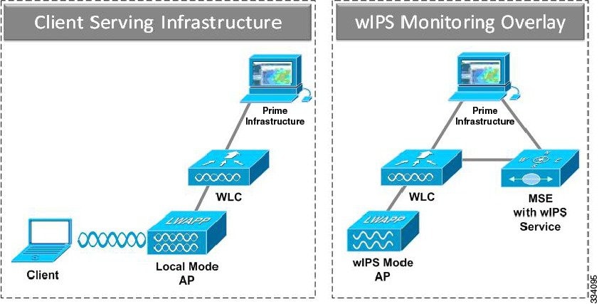
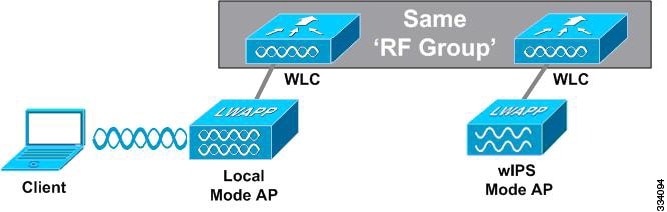
To configure the wIPS Overlay Monitoring network to provide security assessment of the client-serving infrastructure, specific configuration steps must be completed. The wIPS system operates on an assumption that only attacks against trusted devices must be logged. For an overlay system to view a separate Cisco Unified WLAN infrastructure as trusted, the controllers must be in the same RF Group.
As a result of separating the client-serving infrastructure from the wIPS Overlay Monitoring Network, several monitoring caveats arise:
-
wIPS alarms are only shown on the wIPS Overlay Prime Infrastructure instance.
-
Management Frame Protection (MFP) alarms are only shown on the client infrastructure Prime Infrastructure instance.
-
Rogue alarms are shown in both Prime Infrastructure instances.
-
Rogue location accuracy is greater on the client-serving infrastructure Prime Infrastructure because this deployment employs a greater density of access points than the wIPS overlay deployment.
-
Over-the-air rogue mitigation is more scalable in an integrated wIPS model, as the local-mode access points are employed in mitigation actions.
-
The security monitoring dashboard is incomplete on both Prime Infrastructure instances because some events such as wIPS only exist on the wIPS Overlay Prime Infrastructure. To monitor the comprehensive security of the wireless network, both security dashboard instances must be observed.
The below table summarizes some of the key differences between client-serving and overlay deployments.
Table 1 wIPS Client Serving and wIPS Monitoring Overlay Comparison Client-Serving Prime Infrastructure
wIPS Monitoring Overlay Prime Infrastructure
wIPS alarms No Yes MFP alarms Yes No Rogue alarms Yes Yes Rogue location High accuracy Low accuracy Rogue containment Yes Yes, but scalable
One challenge of the overlay solution is the possibility of lightweight access points on either the client-serving infrastructure or wIPS monitoring overlay associating to the wrong controller. Association with the wrong controller can be addressed by specifying the primary, secondary, and tertiary controller names for each access point (both local and wIPS monitor mode). In addition, we recommend that the controllers for each respective solution have separate management VLANs for communication with their respective access points and that access control lists (ACLs) are used to prevent CAPWAP traffic from crossing these VLAN boundaries.
wIPS Overlay in an Autonomous or Other Wireless Network
The wIPS solution is also capable of performing security monitoring over an existing WLAN infrastructure other than CUWN. The application for this deployment is security monitoring of either Cisco autonomous access points or third-party access points.
This figure shows the wIPS overlay in an autonomous network.

Differences Between Controller IDS and wIPS
This section contains the following topics:
- Guidelines and Limitations
- Reduction in False Positives
- Alarm Aggregation
- Forensics
- Rogue Detection
- Anomaly Detection
- Default Configuration Profiles
- Auto MAC Learning Of Valid Clients
Guidelines and Limitations
Forensics
We recommend that the forensics capability of the wIPS system be used sparingly and disabled after the desired information is captured. This is primarily because it places an intensive load on the access point as well as interrupts scheduled channel scanning. A wIPS access point cannot simultaneously perform channel scanning and produce a forensic file. While the forensic file is being dumped, channel scanning is delayed.
Reduction in False Positives
The wIPS facilitates a reduction in false positives with respect to security monitoring of the wireless network, and correlates attack signatures. wIPS triggers an alarm whenever it detects a number of management frames over the air that are causing damage to the wireless infrastructure network. This is a result of the wIPS system being able to dynamically identify the state and validity of access points and clients present in the wireless infrastructure.
Alarm Aggregation
One major difference between the existing Cisco controller-based IDS system and its wIPS system is that the unique attacks seen over the air are correlated and aggregated into a single alarm. This is accomplished by the wIPS system automatically assigning a unique hash key to each particular attack the first time it is identified. If the attack is received by multiple wIPS access points, it is forwarded to the Prime Infrastructure once because alarm aggregation takes place on the Mobility Services Engine. The existing controller-based IDS system does not aggregate alarms. This figure shows the alarm aggregation using Cisco controller-based IDS versus wIPS.

Another major difference between the controller-based IDS and wIPS is the number of attacks that each system can detect. As described in the subsections and shown in the below tables, wIPS can detect a multitude of attacks and attack tools. These attacks include both denial of service (DoS) attacks and security penetration attacks. This section contains the following topics:
- User Authentication and Encryption
- DoS Attacks
- Security Penetration Attacks
- wIPS Alarm Flow
- Performance Violation
User Authentication and Encryption
User authentication and wireless traffic encryption acts as a defense for WLAN security. User authentication blocks out unauthorized access to your wired and wireless resources. Traffic encryption prevents intruders from eavesdropping into the wireless traffic. Common security violations in the authentication and encryption category include misconfiguration, out-of-date software, and suboptimal choice of corporate security policy.
The following table shows the wIPS Security attacks detected by the controller-based IDS and wIPS service.
| Alarm Name | Detected By Controller IDS | Detected By wIPS |
|---|---|---|
|
Static WEP encryption |
||
|
AP with encryption disabled |
X | |
|
Client with encryption disabled |
X | |
|
Crackable WEP IV key used |
X | |
|
Device using open authentication |
X | |
|
Device using shared key authentication |
X | |
|
WEP IV key reused |
X | |
|
WPA and 802.11i |
||
|
802.1x rekey timeout too long |
X | |
|
802.1x unencrypted broadcast or multicast |
X | |
|
AP not protected by EAP-TLS |
X | |
|
Device unprotected by Selected Authentication Methods |
X | |
|
Device not using EAP -TTLS |
X | |
|
Device unprotected by 802.11i/AES |
X | |
|
Device unprotected by 802.1x |
X | |
|
Device unprotected by EAP-FAST |
X | |
|
Device unprotected by PEAP |
X | |
|
Device unprotected by TKIP |
X | |
|
WPA or 802.11i pre-shared key used |
X | |
DoS Attacks
A DoS attack involves mechanisms that are designed to prohibit or slow successful communication within a wireless network. These often incorporate a number of spoofed frames which are designed to drop or falter legitimate connections within the wireless network. Although a DoS attack can be devastating to the ability of a wireless network to deliver reliable services, it does not result in a data breach and its negative consequences are often over once the attack has stopped.
The following table compares the DoS attacks detected by the controller-based IDS and wIPS service.
| Alarm Name | Detected By Controller IDS | Detected By wIPS |
|---|---|---|
|
DoS Attack Against AP |
||
|
Association flood |
X | X |
|
Association table overflow |
X | |
|
Authentication flood |
X | X |
|
EAPOL-Start attack |
X | X |
|
PS-Poll flood |
X | |
|
Probe request flood |
X | |
|
Re-association request flood |
X | |
|
Unauthenticated Association |
X | |
|
DoS Attack Against Infrastructure |
||
|
Beacon flood |
X | |
|
CTS flood |
X | |
|
MDK3-Destruction attack |
X | |
|
Queensland University of Technology Exploit |
X | |
|
RF jamming attack |
X | |
|
RTS flood |
X | |
|
Virtual carrier attack |
X | X |
|
DoS Attack Against Station |
||
|
Authentication-failure attack |
X | |
|
Block ACK flood |
X | |
|
De-Auth broadcast flood |
X | X |
|
De-Auth flood |
X | X |
|
Dis-Assoc broadcast flood |
X | |
|
Dis-Assoc flood |
X | X |
|
EAPOL-Logoff attack |
X | X |
|
FATA-Jack tool |
X | |
|
Premature EAP-Failure |
X | |
|
Premature EAP-Success |
X | |
|
Probe response flood |
X | |
Security Penetration Attacks
Arguably, the more harmful of the two attack types threatening wireless networks, a security penetration is designed to capture or expose information such as sensitive data or encryption keys that can later be used for exposing confidential data. A security penetration attack can involve targeted queries against the infrastructure or replay attacks that aim to break cryptographic keys. Security penetration attacks can also be harmful to the client by which an attempt to lure the client onto a fake access point such as a Honeypot.
The below table compares the security penetration attacks detected by the controller-based IDS and wIPS service
| Alarm Name | Detected by Controller IDS | Detected by wIPS |
|---|---|---|
|
ASLEAP tool detected |
X | X |
|
AirDrop Session dected |
X | |
|
AirPwn |
X | |
|
Airsnarf attack |
X | |
|
Bad EAP-TLS frames |
X | |
|
Beacon Fuzzed Frame Detected |
X | |
|
Brute Force Hidden SSID |
X | X |
|
ChopChop Attack |
X | |
|
DHCP Starvation Attack detected |
X | |
|
Day-Zero attack by WLAN security anomaly |
X | X |
|
Day-zero attack by device security anomaly |
X | |
|
Device Broadcasting XSS SSID |
X | |
|
Device probing for APs |
X | |
|
Dictionary attack on EAP methods |
X | |
|
EAP attack against 802.1x authentication |
X | |
|
Fake APs detected |
X | X |
|
Fake DHCP server detected |
X | |
|
Fast WEP crack tool detected |
X | |
|
Fragmentation Attack |
X | |
|
HT-Intolerant degradation of service |
X | |
|
Honeypot AP detected |
X | X |
|
Hotspotter tool detected |
X | |
|
Identical send and receive address |
X | |
|
Improper broadcast frames |
X | |
|
Karma tool detected |
X | |
|
Malformed 802.11 packets detected |
X | |
|
Man in the middle attack detected |
X | |
|
NetStumbler detected |
X | X |
|
Netstumbler victim detected |
X | X |
|
PSPF violation detected |
X | |
|
Probe Request Fuzzed Frame Detected |
X | |
|
Probe Response Fuzzed Frame Detected |
X | |
|
Soft AP or Host AP detected |
X | |
|
Spoofed MAC address detected |
X | |
|
Suspicious after-hours traffic detected |
X | |
|
Unauthorized association by vendor list |
X | |
|
Unauthorized association detected |
X | |
|
Wellenreiter detected |
X | X |
|
WiFi Protected Setup Pin brute force |
X | |
|
WiFiTap tool detected |
X | |
|
Channel or Device Overload |
||
|
AP Association Capacity full |
X | |
|
AP overloaded by stations |
X | |
|
AP overloaded by utilization |
X | |
|
Excessive Bandwidth usage |
X | |
|
Excessive multicast/broadcast on channel |
X | |
|
Excessive multicast/broadcast on node |
X | |
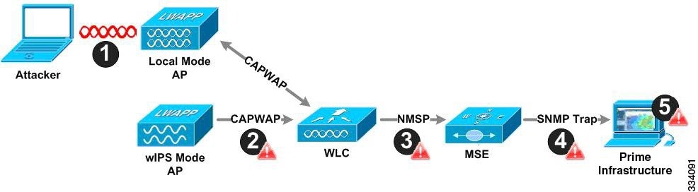
wIPS Alarm Flow
The wIPS system follows a linear chain of communication to propagate attack information obtained from initially scanning the airwaves to forwarding information to the Prime Infrastructure. This figure shows the alarm flow within the wireless network.
-
For an alarm to be triggered on the wIPS system, an attack must be launched against a legitimate access point or client. Legitimate access points and clients are discovered automatically in a CUWN by trusting devices broadcasting the same RF Group name. In this configuration, the system dynamically maintains a list of local-mode access points and their associated clients. The system can also be configured to trust devices by SSID using the SSID Groups feature. Only attacks which are considered harmful to the WLAN infrastructure are propagated upwards to the rest of the system.
-
Once an attack is identified by the wIPS monitor mode access point, an alarm update is sent to the controller and is encapsulated inside the CAPWAP control tunnel.
-
The controller transparently forwards the alarm update from the access point to the wIPS service running on the Mobility Services Engine. The protocol used for this communication is NMSP.
-
Once received by the wIPS service on the Mobility Services Engine, the alarm update is added to the alarm database for archival and attack tracking. An SNMP trap is forwarded to the Prime Infrastructure. The SNMP trap contains the attack information. If multiple alarm updates are received referencing the same attack (for example, if multiple access points hear the same attack), only one SNMP trap is sent to the Prime Infrastructure.
-
The SNMP trap containing the alarm information is received and displayed by the Prime Infrastructure.
Performance Violation
WLAN performance efficiency is challenged by the dynamics of the RF environment and the mobility of the client devices. WLAN performance and efficiency is ensured by the wIPS by monitoring the WLAN and alerting the wireless administrator on early warning signs for trouble. To maximize the use of wIPS, performance alarms can be customized to match the WLAN deployment specification.
The following table shows the Performance Violation detected by the controller-based IDS and wIPS service.
| Alarm Name | Detected By Controller IDS | Detected By wIPS |
|---|---|---|
|
Channel or Device Overload |
||
|
AP association capacity full |
X | |
|
AP overloaded by stations |
X | |
|
AP overloaded by utilization |
X | |
|
Excessive Bandwidth usage |
X | |
|
Excessive multicast/broadcast on channel |
X | |
|
Excessive multicast/broadcast on node |
X | |
Forensics
The Cisco wIPS system provides the ability to capture forensic attacks for further investigation and troubleshooting purposes. At a base level, the forensics capability is a toggle-based packet capture facility which logs and retrieves a set of wireless frames. This feature is enabled on a per-attack basis within a wIPS profile. wIPS profiles are configured on the Prime Infrastructure.
Once enabled, the forensics feature is triggered when a specific attack alarm is seen over the airwaves. The forensic file created is based on the packets contained within the buffer of the wIPS monitor mode access point that triggered the original alarm. This file is transferred to the controller through CAPWAP, which then forwards the forensic file through NMSP to wIPS running on the Mobility Services Engine. The file is stored within the forensic archive on the Mobility Services Engine until the user configured disk space limit for forensics is reached. By default, this limit is 20 Gigabytes, which when reached, causes the oldest forensic files to be removed. Access to the forensic file is obtained by opening the alarm in the Prime Infrastructure which contains a hyperlink to the forensic file. The files are stored in a .CAP file format, which is accessed by either WildPacket Omnipeek, AirMagnet WiFi Analyzer, Wireshark, or any other packet capture program that supports this format. Wireshark is available at http://www.wireshark.org
Rogue Detection
An access point in wIPS-optimized monitor mode performs rogue threat assessment and mitigation using the same logic as current CUWN implementations. This allows a wIPS mode access point to scan, detect and contain rogue access points and ad-hoc networks. Once discovered, this information regarding rogue wireless devices is reported to the Prime Infrastructure where rogue alarm aggregation takes place.
However, with this functionality comes the caveat that if a containment attack is launched using a wIPS mode access point, its ability to perform methodical attack-focused channel scanning is interrupted for the duration of the containment.
Anomaly Detection
wIPS includes specific alarms pertaining to anomalies in attack patterns or device characteristics captured. The anomaly detection system takes into account the historic attack log and device history contained within the Mobility Services Engine to baseline the typical characteristics of the wireless network. The anomaly detection engine is triggered when events or attacks on the system undergo a measurable change as compared to historical data kept on the Mobility Services Engine. For example, if the system regularly captures a few MAC spoofing events each day, and then on another day MAC spoofing events are up 200 percent, an anomaly alarm is triggered on the Mobility Services Engine. This alarm is then sent to the Prime Infrastructure to inform the administrator that something else is happening in the wireless network beyond traditional attacks that the system may encounter. The anomaly detection alarm can also be employed to detect day zero attacks that might not have a pre-existing signature in the wIPS system.
Default Configuration Profiles
To simplify the configuration tuning for each specific WLAN security deployment, wIPS includes a number of default profiles tailored to meet the security needs of specific industries or deployments. The templates summarize the differing risk profiles and requirements for security monitoring of varying deployments. The specific profiles include Education, Enterprise (Best), Enterprise (Rogue), Financial, Healthcare, Hotspot (Open Security), Hotspot (802.1x Security), Military, Retail, Tradeshow, and Warehouse. The profiles can be further customized to address the specific needs of the prospective deployment.
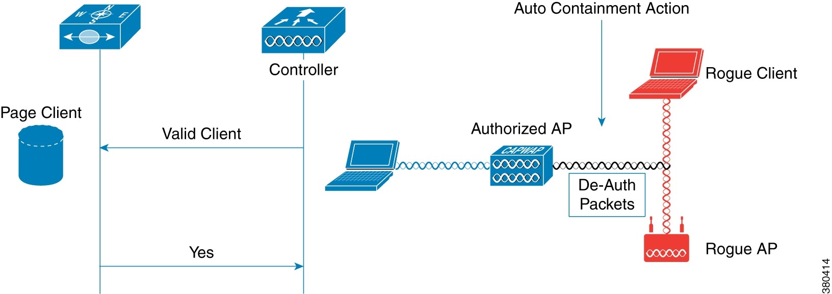
Auto MAC Learning Of Valid Clients
The Auto MAC learning feature is introduced in Release 7.5. This feature protects valid clients on your network from connecting to rogue APs. The MSE is used to validate the clients without any pre-configuration on the MSE.
Whenever a client is connecting to Rogue AP, the controller validates whether the client is valid or not with the MSE. If the client is valid, then controller auto contains the client from connecting to the rogue AP. Controller uses the MSE auto MAC learning database to check each re-association request MAC address.
Note | You need to enable the Auto MAC learning of valid clients feature from the Cisco Controller UI. |
 Feedback