Overview
Cisco Hyperlocation is an enhanced location solution that takes advantage of the specialized hardware that is available on the Cisco Aironet 4800 Series wireless Access Points. It uses Angle-of-Arrival of Wi-Fi signals to determine the location of connected mobile devices. While other technologies are using RSSI to get location within 10 meters of accuracy, Cisco Hyperlocation can track locations to within three meters in an optimized deployment. You can integrate Cisco Hyperlocation with other Cisco wireless location solutions for additional uses. Combining it with Cisco Workplace Analytics, for instance, can result in more precise utilization analytics that helps you better understand your workplace usage.
This document outlines the best practices to follow when deploying the AP4800 Hyperlocation solution. It outlines specific areas to keep in mind to ensure that the technology produces accurate and precise location measurements as expected by the end user.
Hyperlocation in Cisco Connected Mobile Experiences: The Hyperlocation Solution substantially increases the location accuracy for connected clients of the Connected Mobile Experiences. The FastLocate technology boosts the refresh rate so CMX captures more location data points. And the Angle-of-Arrival capabilities increases location accuracy to as close as one meter (50% Error Distance). The improved accuracy provides more granular analytics data compared to RSSI based location.
Bluetooth Low Energy "BLE" support for CMX: In addition to the Hyperlocation Solution, the AP4800 includes and integrated BLE radio that can can detect BLE beacons installed in the venue and transmit BLE Beacons in iBeacon or Eddystone format.
How does Hyperlocation work ?
Hyperlocation radios and antennas are programmed with which MAC addresses they should report for, this is based on the associated clients of “surrounding” AP’s. Surrounding APs are based on which AP can hear the packets from the client serving AP/radio that has the Hyperlocation AP (L1 List). When clients are “quiet” the serving radio is interrupted to send BAR (Block Acknowledgement Request) packets to the client to awake it up. Location is a “FUSION” of the RSSI calculated location and AoA calculated location if both are available.
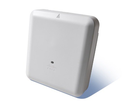
AP 4800 Antenna System
The Hyperlocation (circular antenna array) is a 16-element antenna design that provides 360-degree coverage around the access point. It is designed to provide precise RF Angle-of-Arrival (AoA) information providing the embedded software the data required to calculate location using a more granular approach.
If you could take the cover off the product, here is how it would break down: 4 macro- and 4 micro-cell elements for client connectivity, 16 element circular antenna array for Hyperlocation, 4 elements of the array are used as an omnidirectional antenna for monitoring and the BLE antenna in the center.

Hyperlocation Deployment
Before installing Hyperlocation it would be good for the installer/operator to become familiar with the operation of Cisco Prime Infrastructure, CMX and current methods of performing Real Time Location Systems (RTLS) using conventional signal strength (RSSI) if possible. Refer to the Chapter: Best Practices—Location-Aware WLAN Design Consideration of the Wi-Fi Location-Based Services 4.1 Design Guide at https://www.cisco.com/c/en/us/td/docs/solutions/Enterprise/Mobility/WiFiLBS-DG/wifich5.html for AP placement and more site survey details.
Preparing the Site for Hyperlocation
It is very important that the installer and network administrator work together to determine proper AP placement from both a physical installation and a software location placement onto the Prime Infrastructure (PI) map. It is critical that the administrator properly and accurately document the X, Y position, height and antenna orientation of the APs on the map.
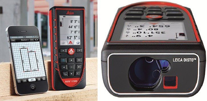
Tools that can assist with this job would be:
-
A plumb bob (weighted string) to can mark the location of the ceiling mounted AP on the floor
-
Laser range finder or measurement wheel (to measure distances accurately)
-
Tri-Pod or other leveling device for use with laser
-
Laser pointer
Physical Placement of the Hyperlocation Access Point
Some basic guidelines on Site Surveys or deployments are:
-
Try to maintain consistent -65 dBm RSSI for data, voice, video, location
-
In order to achieve the best accuracy results, a site survey is required
-
20% cell overlap for optimized roaming and location calculations
-
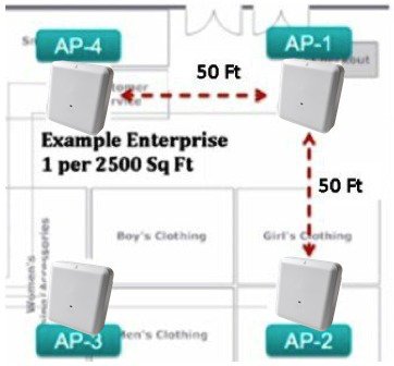
A good rule of thumb is 1 Access Point per 2,500 square feet / 250m2 (best performance) or more, but site specific. AP density should be determined through a site survey
-
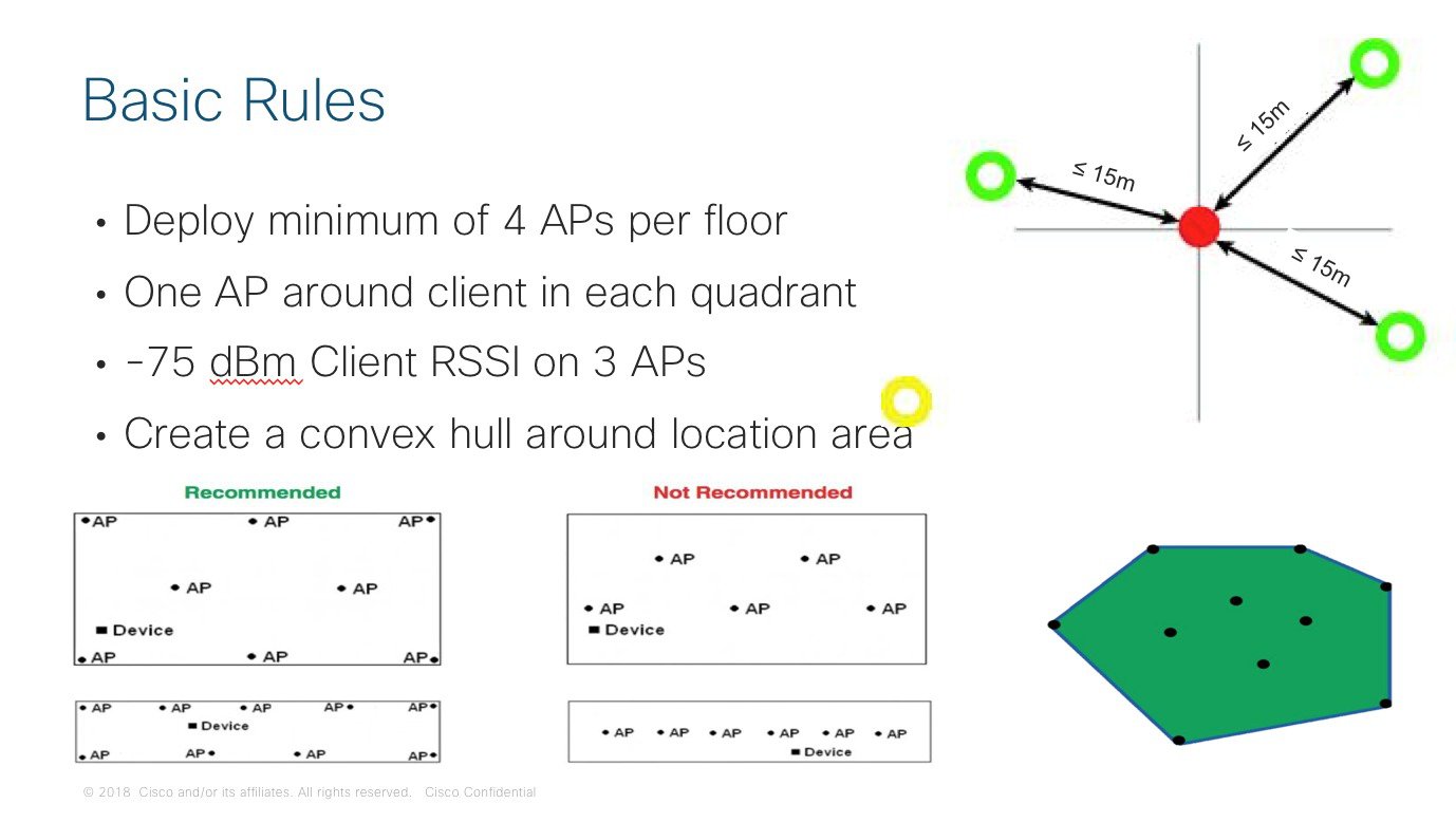
Keep AP to AP distance below 50ft / 15m
-
Keep AP height below 15ft / 4.5m
-
For location create a convex hull around the coverage area, start with AP’s placed on the perimeter
-
For high density applications, it is recommended to add an additional AP in the middle of dense areas
-
Additionally, try to stagger the APs so you cover the perimeter and try to design so that at least four APs are within line of sight of the clients
-
Do not mount APs for Hyperlocation above ceiling tiles. Obstruction and metal elements will dramatically degrade the Hyperlocation performance
-
If there is a requirement to mount the AP4800 access point on a wall, in-ceiling, hide or change the color. Mounting kit for optimal AP positioning are available from Cisco partners and third-party solution providers
Importance for Hyperlocation
For optimal performance unobstructed line of sight between the client and four Hyperlocation APs is important. Location is only good inside the convex hull formed by the APs. Even with using AoA the performance of Hyperlocation suffers when the clients are outside the convex hull.
You should capture the following after mounting the AP:
-
AP name and AP MAC address
-
Map location of the AP
-
Exact position with an accuracy of 1ft / 30cm. You can capture the exact distance to two walls or three points. This can be used in Prime Infrastructure to exactly position the AP on the map
-
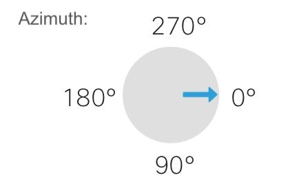
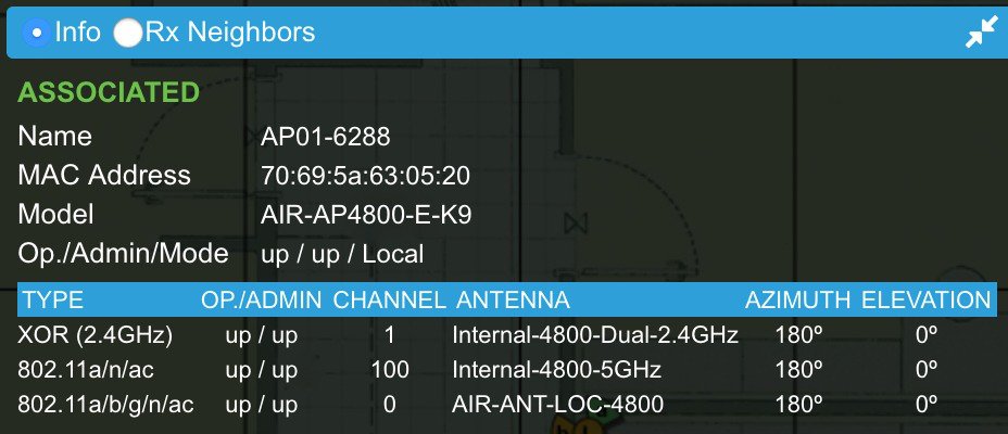
Orientation of the AP: Azimuth with an accuracy of 5 degrees. Hyperlocation APs should be mounted horizontally, so elevation is always 0 degrees. The AP has an arrow, which helps you identifying the antenna orientation. You will save a lot of time if you can align all APs on a floor to point in the same direction.
In Prime Infrastructure 0° is pointing to the right, 90° down, 180° to the left and 270° to the top of the map
 Note |
In Prime Infrastructure the default azimuth of an AP when added to a map is 90°. Mounting the APs with the arrow pointing to 90° would save time when positioning the APs on the floorplan in Prime Infrastructure. |
Location errors are compounded when the locations of Hyperlocation APs are not properly documented.
If you are mounting the units to the ceiling grid, it is recommended that you orientate all of the Access Points in the same direction. This will make it easier when recording them. If you are not mounting to the ceiling rails, use a laser pointer or other device to try and align them in the same direction.
Oftentimes, it is difficult to measure and map the location when the AP4800 unit is mounted high on a ceiling. In these cases, it is suggested that the use of a plumb bob dropped from the center of the AP or a laser pointer be used to mark the exact location on the floor so that a tape measure or laser range finder can be used.
Mixed Mode
Mixing of AP4800 Hyperlocation APs and Non-Hyperlocation APs on the same map a feature included in CMX 10.5. This is meant for areas where higher accuracy is needed. High accuracy areas then will be covered with AP4800 while in other areas on the map Non-Hyperlocation APs can be used. Hyperlocation APs have to create a convex hull around this zone and all additional APs inside the zone also have to support Hyperlocation. A salt-and-pepper design is not supported.
Installation and Configuration
Prerequisites
Cisco Wireless LAN Controller
The following Wireless LAN Controllers are supported:
-
Cisco 3504 Wireless Controller
-
Cisco 5520 Wireless Controller
-
Cisco 8540 Wireless Controller
Virtual Wireless LAN Controller and Mobility Express are not supported for Hyperlocation.
Minimum WLC Software Version for AP4800 with Hyperlocation is AireOS 8.7.106.
CMX needs a read-write SNMPv2 community or a SNMPv3 user with read-write access on the WLC.
Prime Infrastructure
PI is needed to create the necessary floor plans, position APs on the map and create GPS markers.
Minimum Prime Infrastructure is PI 3.4.
After adding the WLCs to PI joined APs will be added automatically to the device list. See next chapter for adding and placing APs on the floorplans.
Networking and Firewall
If any firewalls exist between WLC and the CMX server the following ports need to be open:
-
16113 NMSP
-
2003 Fastpath for AoA and FastLocate data
-
443 HTTPS
-
161, 162 SNMP
-
ICMP
Network Time Protocol (NTP)
Hyperlocation requires exact clock synchronization for Access Points, Wireless Controller and CMX. NTP is a hard requirement and operation without working NTP is not supported. NTP settings on the WLC can be fount at: Wireless > Access Points > Global Configuration > Hyperlocation provides the NTP configuration for the APs. This NTP needs to be reachable from the AP subnets. See the Enable Hyperlocation section for configuration details.
AP placement in Prime Infrastructure
The following steps are necessary before you can start adding APs to the map:
-
Create your map hierarchy: Campus – Buildings–Floors
-
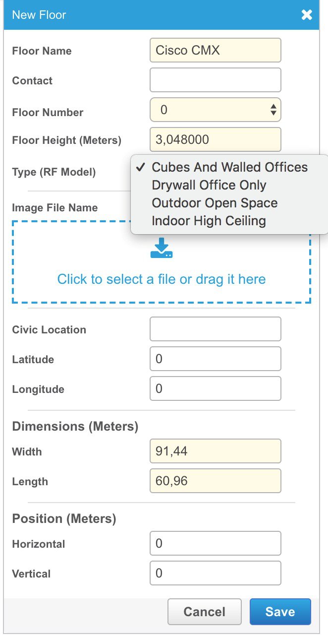
Properly size the floors. The height should match your highest AP mounting position on that floor. The AP height will default to your ceiling height
-
Select the Floor Type RF model which is the closest match to your environment: Cubes and Walled Offices, Drywall Office Only, Outdoor Open Space, Indoor High Ceiling (Figure 7 Select the correct Type (RF Model))
-
Add the floorplan image and scale it correctly
-
Add the APs to the floors and position them. (Figure 8 AP position and orientation)
-
Drag the APs to the correct location or use Position by 3 points / 2 walls to position the AP (Figure 8 AP position and orientation)
-
Orientation of the Hyperlocation Antenna must be entered correctly.

Note |
AP templates can help applying antenna orientation to a bulk of APs |
For more details on how to work with Wireless Site Maps in PI see the PI User Guide at https://www.cisco.com/c/en/us/td/docs/net_mgmt/prime/infrastructure/3-4/user/guide/bk_CiscoPrimeInfrastructure_3_4_0_UserGuide/bk_CiscoPrimeInfrastructure_3_4_0_UserGuide_chapter_01010.html
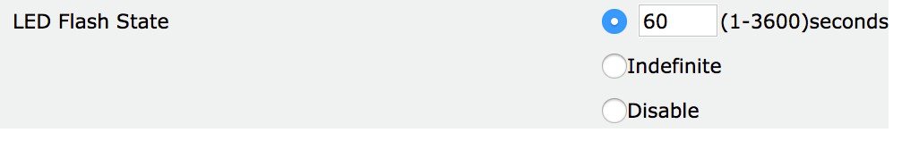
One common error is APs are at the right position, but swapped. i.e. AP has been installed on a location for another AP. To verify on site the right AP is at the right location you can use the blink LED feature of the AP. On the WLC go to Wireless > Access Points > All APs > select the AP in question > go to advanced tab > select the LED flash state. The LED will start blinking blue – red – green.
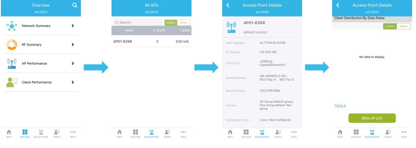
The Cisco Wireless mobile application for iOS and Android can also be used to blink the AP LED. Use the app to connect to your WLC, in the app select Access Points > select the AP in question > scroll down to the bottom of the page > click “Blink AP LED”.
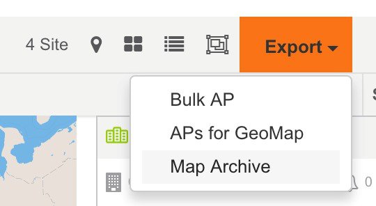
After you have finished and verified the maps you need to export them following these steps:
-
Go to Maps > Site Maps and select Export Map Archive from the drop down
-
Select the sites you want to export to CMX, leave Map Information and Calibration information ON and include the calibration information for selected maps
-
Select “Generate Map Archive”, this will initiate the download to your PC.
CMX Installation
Hyperlocation with AP4800 requires CMX 10.5. Hyperlocation is only supported on CMX hardware appliance and high-end virtual appliances. See Appendix URL #4 and URL #5 for installation instructions.
-
CMX virtual appliance Installation Guide https://www.cisco.com/c/en/us/td/docs/wireless/mse/10-4/installation/guide/installation_guide_104.html
-
Cisco MSE 3365 Installation Guide: https://www.cisco.com/c/en/us/td/docs/wireless/mse/3365/installation/guide/mse3365-installation-guide.html
Before turning on the VM the first time it is recommended to increase the disk size to 1 TB by editing the VM settings.
Make sure to have a proper network configuration:
-
Hostname should be changed from localhost to a FQDN
-
Valid NTP and time zone configuration
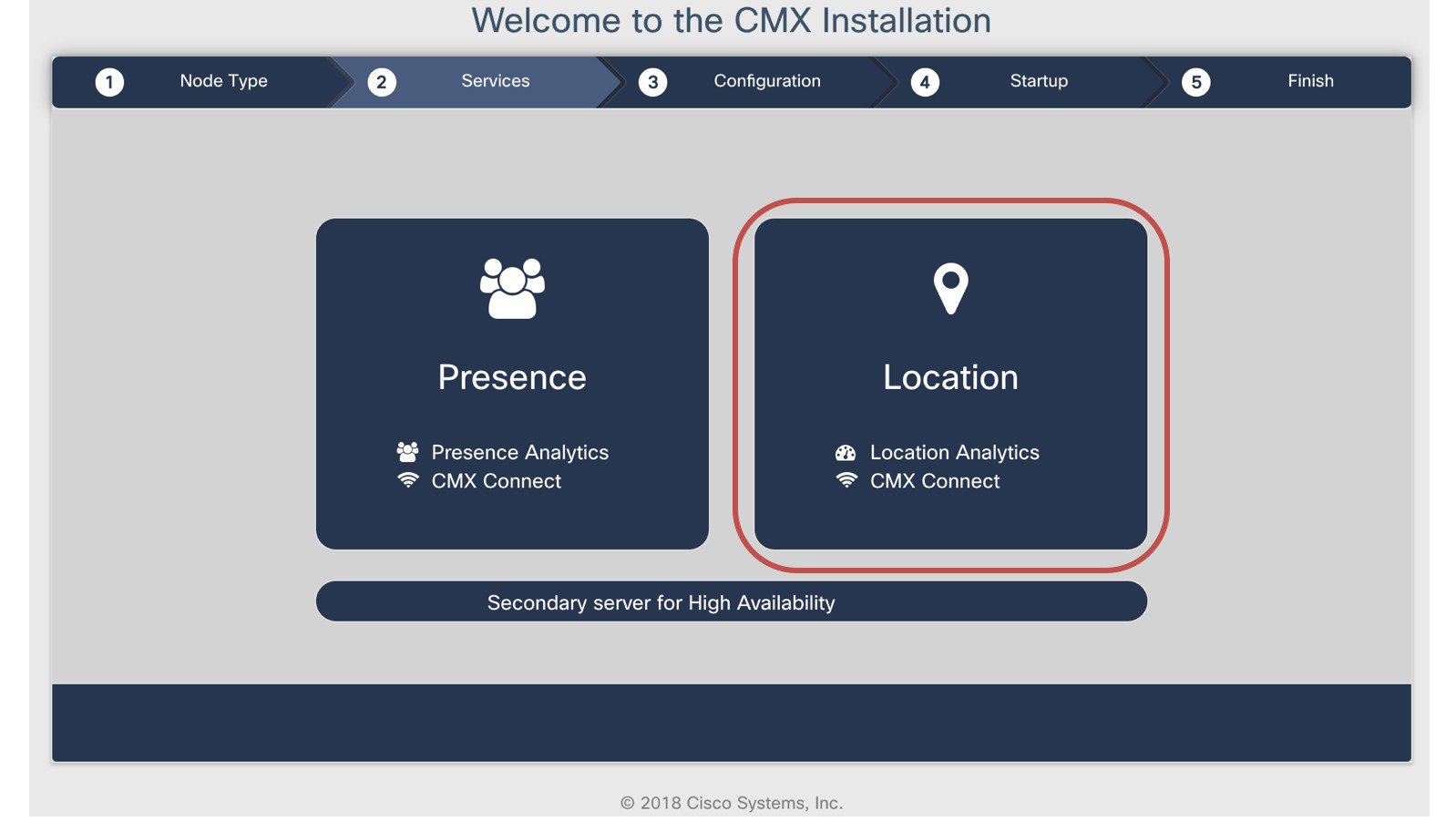
After OS configuration you will be asked to connect to CMX via HTTPS on port 1984. After login with username cmxadmin you will be prompted to select the installation type. Select: Location (Figure 11 Service Selection). Presence does not support Hyperlocation. You can add a secondary server for high availability at anytime later on.
After CMX has been installed for location you will be prompted to continue with the setup. Click the link.
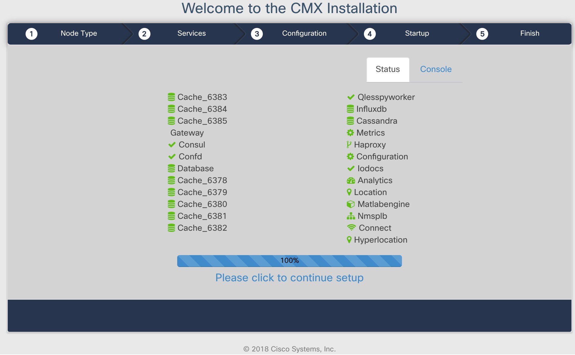
This will redirect you to the CMX setup assistant
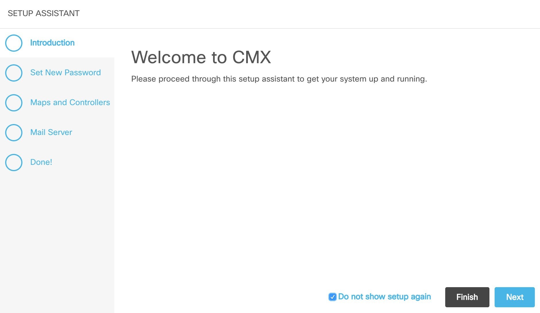
The setup assistant allows you only to import all maps and controllers from PI to CMX. If you want only to import selected maps and wireless controllers only cancel the assistant after setting the password for the GUI admin user and follow the steps below. Do not forget to finish the Mail Server configuration later.
Hyperlocation Configuration
After CMX installation has been finished, reboot the system and verify configuration and NTP. Login to the console or via SSH:
Use: cmxos verify to check VM configuration. For Hyperlocation you should meet the requirements for a high-end VM:
-
20 vCPUs, 64 GB Memory, 1 TB Disk space
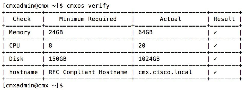
Use: ntpstat to check NTP is working correctly. IP of the NTP server should match your configuration. Output should say “synchronized to NTP server”.
-
Import maps to CMX by navigating to System > Settings > Controllers and Maps Setup > Advanced
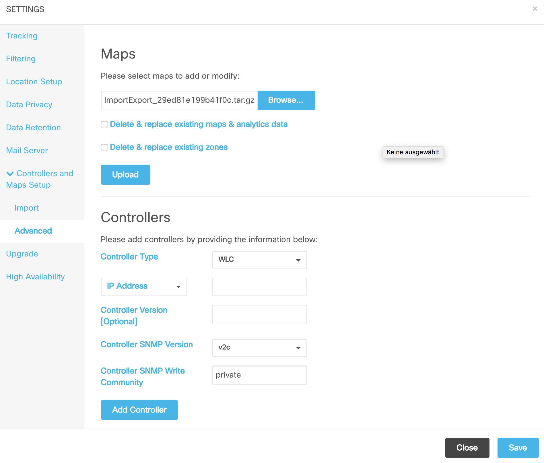
Browse to the map export file you created with PI and upload.
-
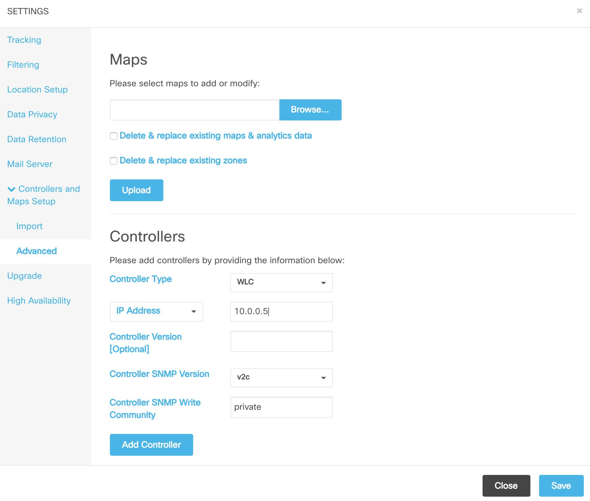
Add wireless controllers by navigating to System > Settings > Controllers and Maps Setup > Advanced
Enable Hyperlocation on WLC
First verify the NTP settings for the WLC.
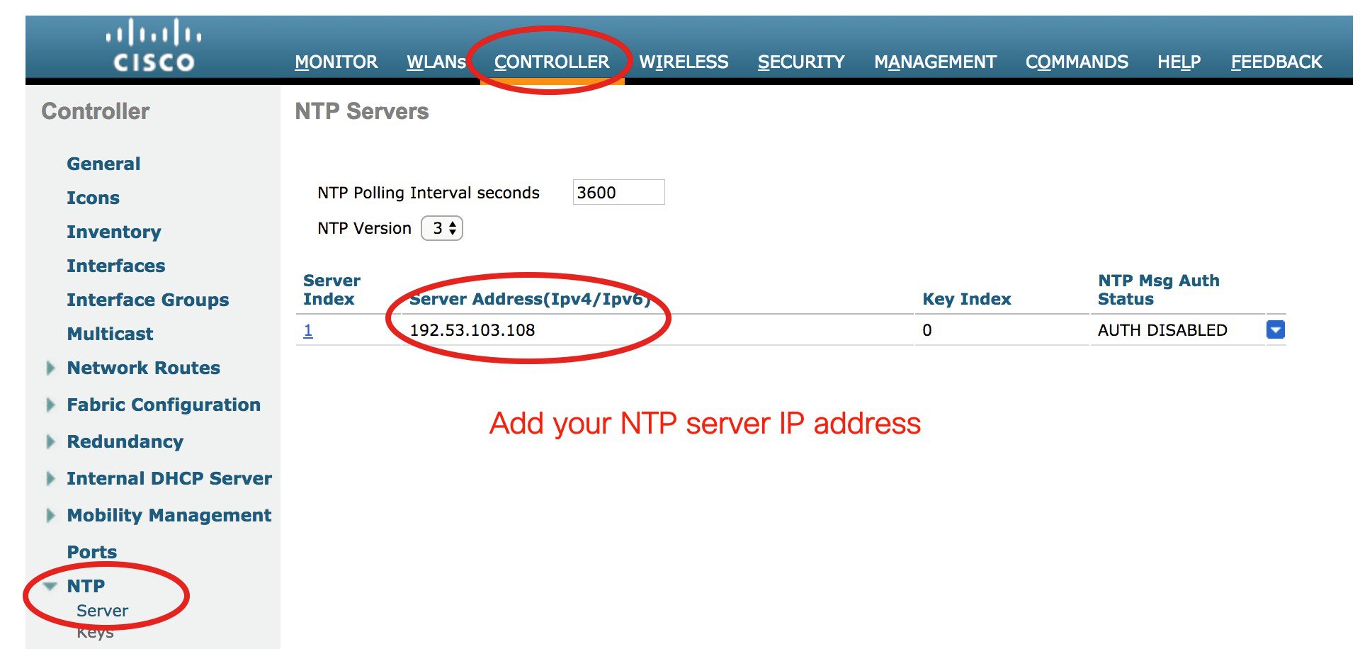
After configuring NTP for the WLC you can enable Hyperlocation for the APs. You also need to set a NTP server IP for the Access Points through the Hyperlocation setting. This NTP server must be reachable from the AP subnet.

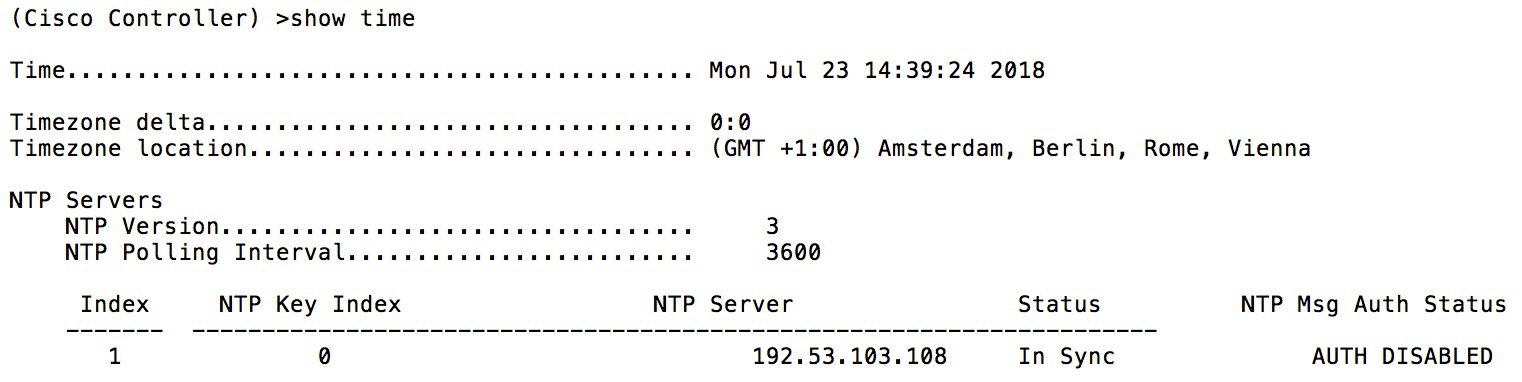
Login to WLC via SSH or console and check the NTP server is synced.
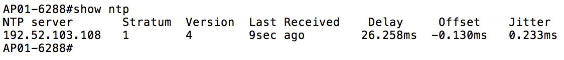
To verify proper NTP operation on the APs login to the AP via SSH or console.
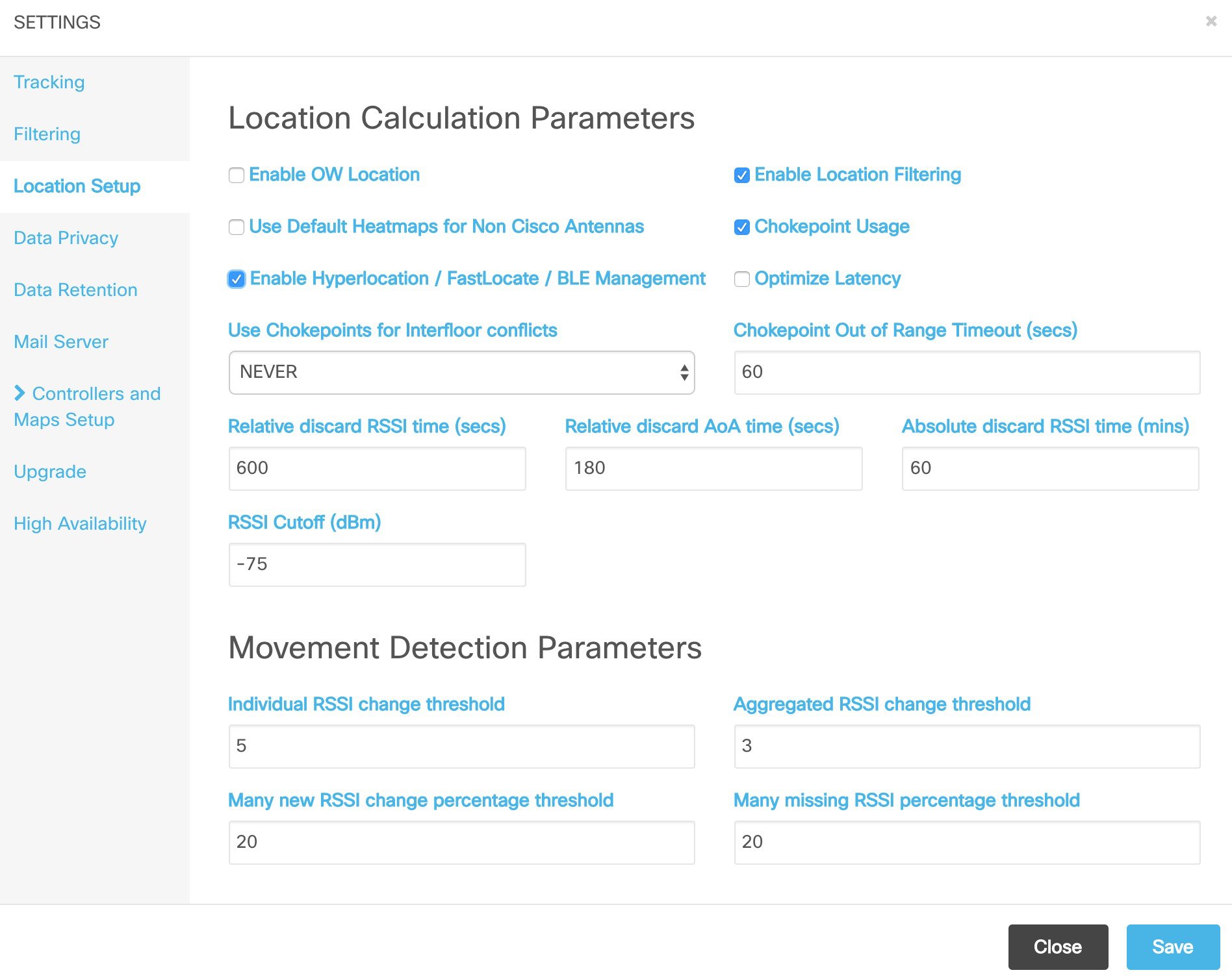
Enable Hyperlocation on CMX
Go to System > Settings > Location Setup and enable Hyperlocation.
Restart CMX services
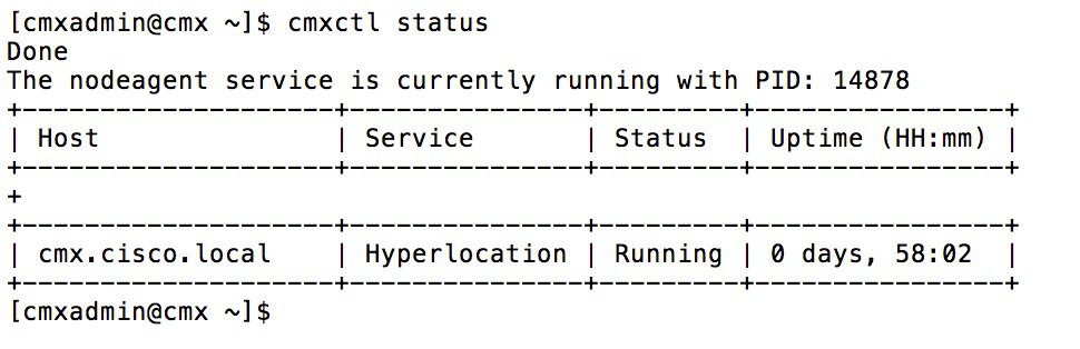
After enabling Hyperlocation on CMX it is required to restart the services. Login to the console or through SSH and use the cmxctl stop and cmxctl start command to stop and restart the services. Check with cmxctl status if Hyperlocation service is running.
Restart APs
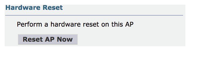
After enabling Hyperlocation on CMX it is also required to restart the APs. Use Prime Infrastructure, the WLC GUI or WLC CLI to restart APs. You can also power cycle the APs from the Switch.
Mixed Mode Deployment
If you have a deployment where only zones are covered with AP4800 and other APs on the same map do not support Hyperlocation you have to enable Mixmode for this floor. Mixmode needs to be enable per floor on the CMX CLI with the cmxctl config hyperlocation mixmode command. See the CMX Command Reference Guide at https://www.cisco.com/c/en/us/td/docs/wireless/mse/10-4/cmx_command/cmxcli104/cisco_cmx_commands.html
You have to restart CMX services after enabling mixmode.
Verify Hyperlocation settings
Before starting testing location accuracy, it is recommended to verify Hyperlocation is configured correctly.
Verify on WLC
On the WLC GUI navigate to Monitor > Cloud Service > CMX.
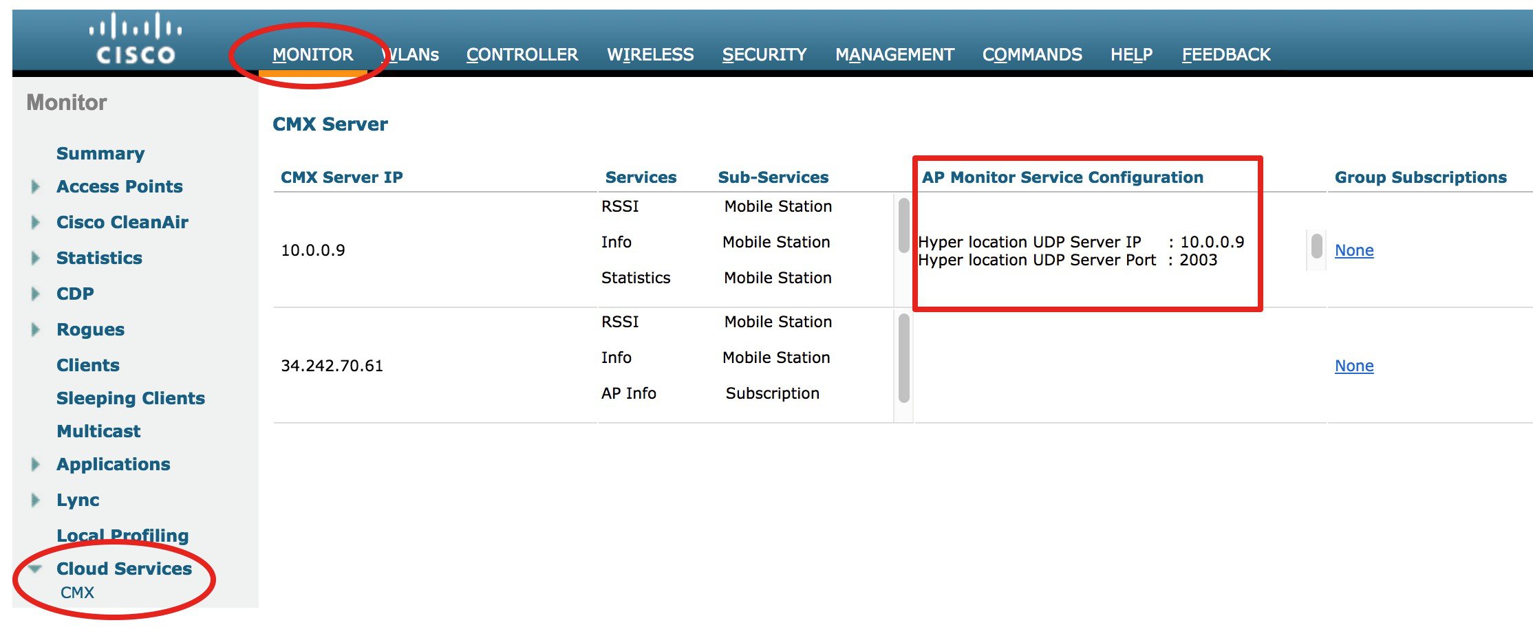
The AP Monitor Service Configuration should show the IP of your CMX. This is the Fastpath configuration of the APs for AoA data. If you have multiple APs connected with your WLC check the Group Subscription.
Verify using CLI
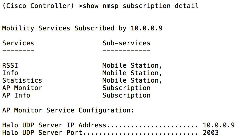
Login to your WLC via console or ssh. Use the command show nmsp subscription detail to show your CMX IP under Halo UDP Server IP Address:
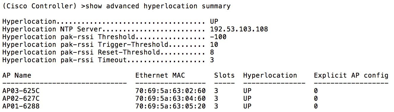
Use the command show advanced hyperlocation summary to check Hyperlocation is UP on all your AP4800.
Verify on CMX
Verify APs on maps
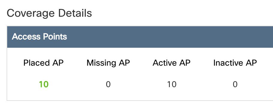
On CMX GUI navigate to the System dashboard and check coverage details for missing or inactive APs.
-
Placed AP: Number of APs placed on the imported maps
-
Missing AP: CMX is getting data from AP, but the AP is not placed on a map; check your maps
-
Active AP: Number of AP CMX is getting data and placed on map
-
Inactive AP: AP is placed on map, but CMX is not getting data, should be zero
Check for incoming AoA messages
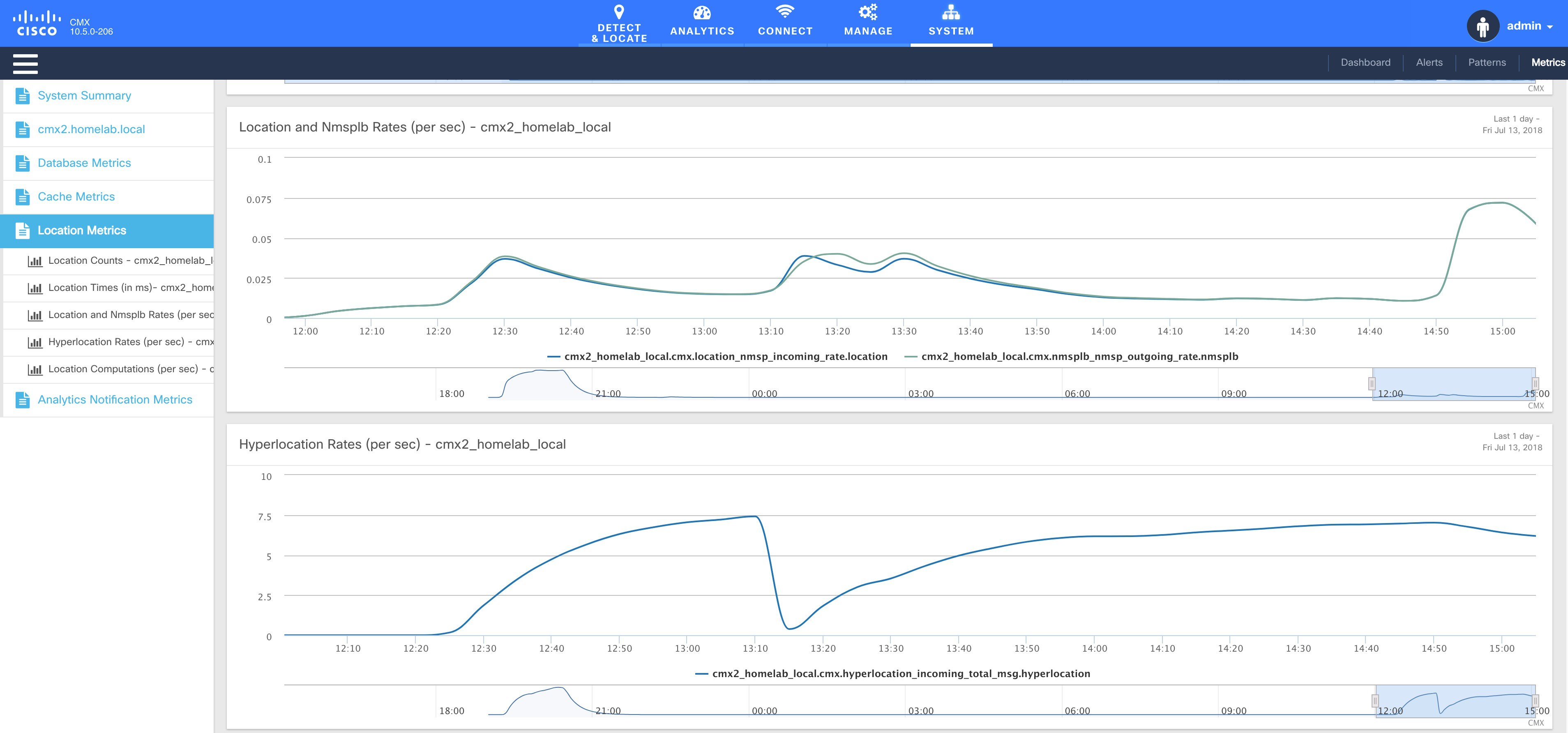
Make sure at least one client is connected to your wireless network and to one of your Hyperlocation APs. On CMX navigate to System > Metrics and select the Location Metrics. Hyperlocation Rate should be different from zero. The example screenshot shows a single client.
Accuracy Testing
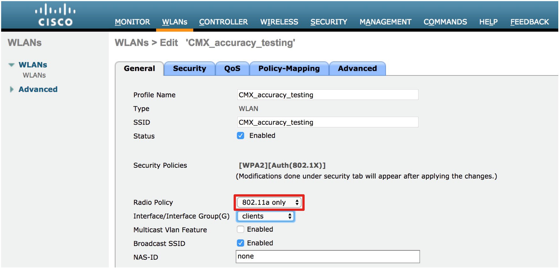
You need at least one connected client for accuracy testing. Creating a 5 GHz only WLAN SSID will ensure you have the most accurate location test.
Accuracy testing is done with a static device. Make sure your test points are inside the convex hull of your AP coverage. It is recommended to collect 25-50 samples per point. Repeat the test in multiple locations throughout your coverage area. Accuracy tests will not improve location accuracy as the results will not be used for any kind of calibration. You might want to use different clients at the same location to understand the client impact on accuracy.
-
Choose a client for your accuracy test
-
Pick multiple points across your venue, note the X, Y of your test points
-
Execute the test on each of the points and collect 25-50 measurements per point
-
Finish the test and review the test results
You can execute the tests using GUI or CLI. GUI is a bit more comfortable, while CLI gives you a few more details while the test is executed.
Testing accuracy using GUI
To execute accuracy tests, via the GUI on CMX navigate to the Detect & Locate tab. Selecting the client (green dot on the map) will expand the Client details pane on the left. Use the pin icon to start the test. The number of samples will be updated. After collecting enough sampled click pause and then finish to end the test.
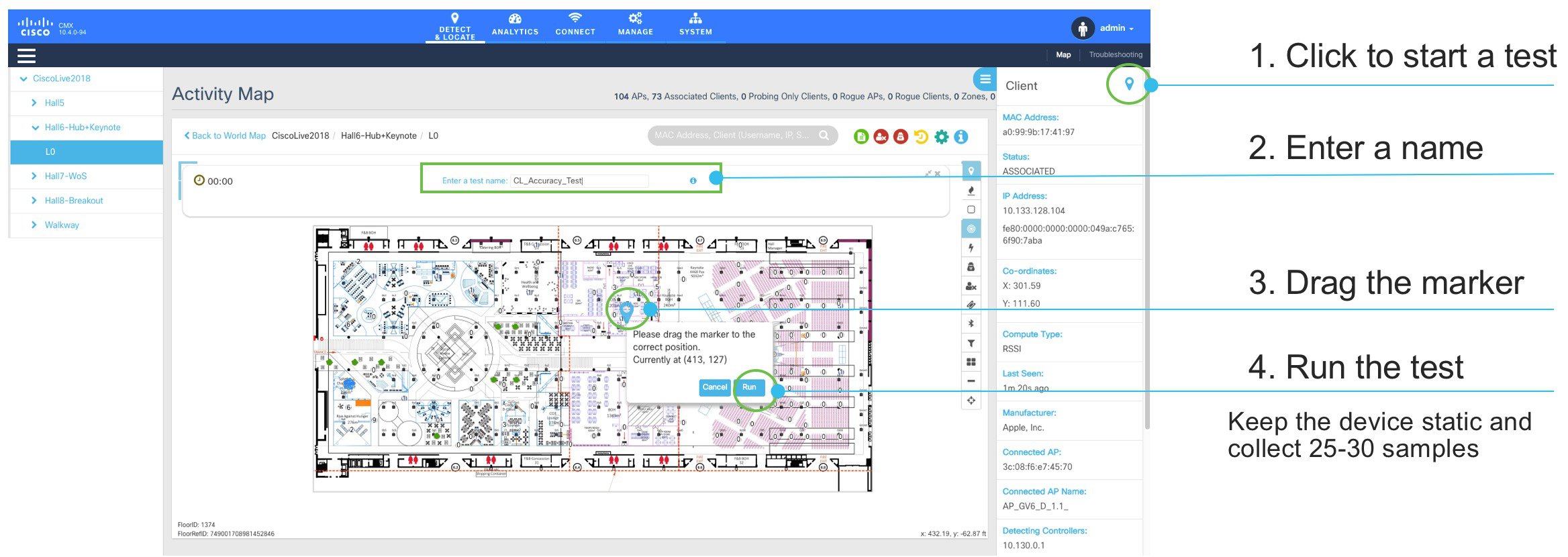
Test results can be viewed by clicking on the green icon .
Testing accuracy using CLI
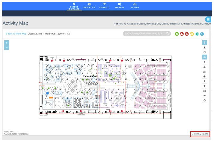
You need the X, Y of your test points. You can use the CMX GUI Detect & Locate tab, select the map and move your mouse pointer to the test point, you can read the X and Y coordinates on the bottom right of your map.
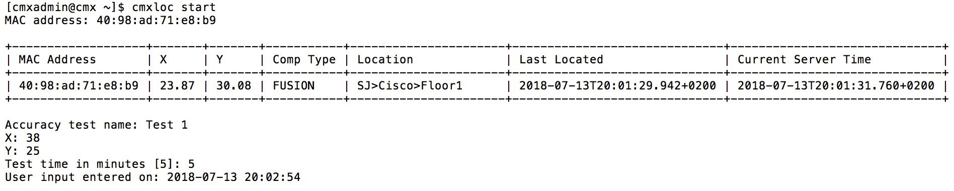
Login using console or SSH to your CMX. To start a location accuracy test, use the cmxloc start command. You will be prompted to enter the client MAC address, a test name and the X, Y of the real location. You can also select the duration of the test.
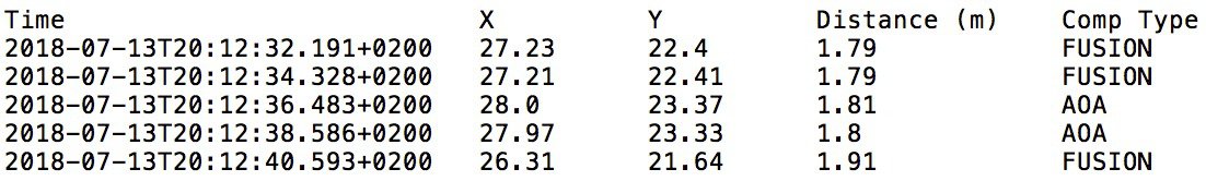
During the test you will see the computation method of each data point: RSSI, AoA or FUSION.
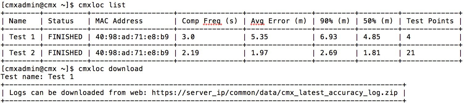
To view the test results, use the cmxloc list, cmxloc download can be used to prepare a zip file which is helpful for troubleshooting. Use the provided URL, replace the server_IP with the IP of your CMX server to download the zip file.
Understanding the test results
On CMX GUI navigate to Detect & Locate and click the green icon to view the test results table.
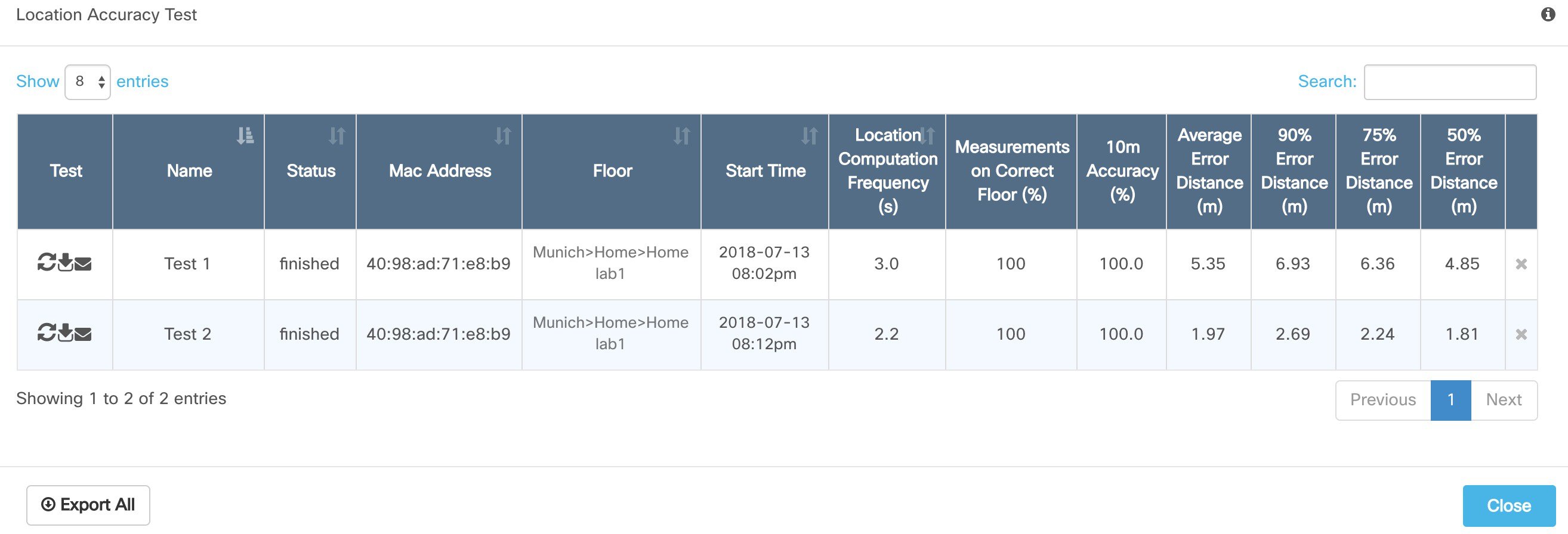
The table shows the following columns:
-
Test: allows you to relaunch, download and send an e-mail with the test results
-
Name: Name of the test
-
Status: running, paused or finished. You can pause and finish a running test from here.
-
Mac Address of the test device
-
Floor of the accuracy test
-
Start Time of the test
-
Location Computation Frequency: Average time between location updates / calculations during the test. Should be better than 10s for Hyperlocation
-
Measurements on Correct Floor in %: In some situation, especially when there are atriums / open ceilings the client will be detected from APs on other floors as well and the algorithm might choose the wrong floor
-
10m Accuracy in %: How many of the calculations are within 10 meters of the real location during the test.
-
Average distance error in meters: averaged location error during the test
-
90% / 75% / 50% error distance in meters: This indicates the radius of 90% / 75% and 50% of the calculated locations around the real location. Good deployments should be in the range of 1-3m for the 50% error distance
Appendix
-
Cisco Aironet Series 4800Access Point Deployment Guide: https://www.cisco.com/c/en/us/td/docs/wireless/controller/technotes/8-7/b_cisco_aiironet_series_4800_acces_point_deployment_guide.pdf
-
Cisco CMX Command Reference Guide: https://www.cisco.com/c/en/us/td/docs/wireless/mse/10-4/cmx_command/cmxcli104/cisco_cmx_commands.html
-
Cisco Prime Infrastructure User Guide:https://www.cisco.com/c/en/us/td/docs/net_mgmt/prime/infrastructure/3-4/user/guide/bk_CiscoPrimeInfrastructure_3_4_0_UserGuide.html
-
CMX virtual appliance Installation Guide: https://www.cisco.com/c/en/us/td/docs/wireless/mse/10-4/installation/guide/installation_guide_104.html
-
Cisco MSE 3365 Installation Guide: https://www.cisco.com/c/en/us/td/docs/wireless/mse/3365/installation/guide/mse3365-installation-guide.html
-
Wi-Fi Location-Based Services 4.1 Design Guide: https://www.cisco.com/c/en/us/td/docs/solutions/Enterprise/Mobility/WiFiLBS-DG.html
-
Cisco CMX Configuration Guide: https://www.cisco.com/c/en/us/td/docs/wireless/mse/10-3/cmx_config/b_cg_cmx103.html
 Feedback