Cisco 5760 IOS Wireless LAN Controller Configuration Best Practices
Available Languages
Table of Contents
Cisco 5760 IOS Wireless LAN Controller Configuration Best Practices
Enable Network Time Protocol (NTP) and Setup Time
Use PortFast on AP Connected Switch Ports
Link Aggregation and Port Redundancy
Dynamic Channel Assignment (DCA)
Dynamic Frequency Selection (DFS)
Identity Design Tip - Use AAA Override
Create SNMP Community and Users
SNMP Best Practices for Prime and IOS-XE Controllers
Application Visibility and Control (AVC)
Enable High Availability AP SSO
AP Stateful Switchover (AP SSO)
StackWise-480 Connectivity for HA
Enable Rogue Clients AAA Validation
Enable Rogue Clients MSE Validation
Introduction
Mobility has rapidly changed how we use, and what we expect of wireless network resources. Wireless has become the preferred option for users to access the network, and in a lot of cases the only practical one. This document offers short configuration tips that cover common best practices in a typical Wireless Unified Infrastructure. The objective is to provide important notes that you can apply on most wireless network implementations.
This document focuses on the 5760 Wireless LAN Controller (WLC), which uses the Cisco IOS-XE as its operating system.

Note![]() Not all networks are equal. Therefore, some tips might not be applicable on your installation. Always verify them before you perform any changes on a live network.
Not all networks are equal. Therefore, some tips might not be applicable on your installation. Always verify them before you perform any changes on a live network.
Prerequisites
Requirements
Cisco recommends that you have knowledge of these topics:
- Knowledge of how to configure the Wireless LAN Controller (WLC) and Lightweight Access Point (LAP) for basic operation
- Basic knowledge of Control And Provisioning of Wireless Access Points (CAPWAP) protocol and wireless security methods
- Cisco IOS Command Line Interface
- Cisco CT5760 Controller Deployment Guide
Components Used
The information in this document is based on these software and hardware versions:
- Cisco Series WLC 5760 that runs firmware Release 3.3 and later
- Cisco 802.11n/ac series Access Points
Note![]() Any reference to WLCs is based on firmware Release 3.3 and later.
Any reference to WLCs is based on firmware Release 3.3 and later.
The information in this document was created from the devices in a specific lab environment. All of the devices used in this document started with a cleared (default) configuration. If your network is live, ensure that you understand the potential impact of any command.
New Operating System
The CT5760 controllers use the Cisco IOS-XE software as its operating system. The CLI is different from the CLI used in the AireOS platforms. For a complete list of the wireless Cisco IOS-XE software CLI commands, refer to the Cisco 5700 Series Wireless LAN Controllers Command References document.
Best Practices
This is a summary table for best practices recommended in this document. Please refer to individual sections for additional details.
Software Version
The CT5760 currently ships with release 3.2.01 or release 3.3.0. You can check this using the following command:
Switch Ports Model SW Version SW Image Mode
------ ----- ----- ---------- ---------- ----
* 1 6 AIR-CT5760 03.03.01SE ct5760-ipservicesk9 INSTALL
It is recommended to upgrade to software release 3.3.2 and later. Latest software codes are available on cisco.com. It is best practice to go through the release notes before upgrading to that software code. Follow the steps in the Cisco IOS-XE software upgrade document.
GUI Usage
For the purpose of this document, CLI commands were used to make the configurations. However, most of the changes mentioned in this document can be done using the GUI.
You can access the GUI by configuring the out of band management port (GigE 0/0) or use existing reachable configured interfaces through the network, that is, create a VLAN and L3 interface to reach the controller.
For best GUI experience, it is best practice to follow the steps:
1.![]() Use the list of supported browsers:
Use the list of supported browsers:
2.![]() Upgrade the controller to the latest software version that has additional features and GUI support.
Upgrade the controller to the latest software version that has additional features and GUI support.
3.![]() You will need to create a user name and password to access the GUI. You can configure a local user name by issuing the CLI below or you can configure it to use credentials using an authentication server. Ensure that the user has privilege 15 as an access level.
You will need to create a user name and password to access the GUI. You can configure a local user name by issuing the CLI below or you can configure it to use credentials using an authentication server. Ensure that the user has privilege 15 as an access level.
4.![]() By default, https is enabled. You can access the web GUI through https but if you want to enable http access, you can do so by issuing the CLI below:
By default, https is enabled. You can access the web GUI through https but if you want to enable http access, you can do so by issuing the CLI below:
WLC5760(config)#username <username> privilege 15 password <password>
WLC5760(config)#ip http secure-server
WLC5760(config)#ip http authentication local
Note![]() The
The ip http authentication local CLI may not be configured by default in previous releases. However, it is configured by default in recent releases. Ensure it is configured once you upgrade to the latest release.
Enable SSHv2
If you need to SSH to your controller, use SSHv2. Ensure that the SSH protocol v2 is supported on your SSH client side. Most SSH clients support SSHv2.
AP Join
Before connecting your Access Points to the network, ensure licenses and the correct time is set on the controller.
Licenses
Licenses are based on the Right-To-Use license model (per AP license price for the CT5760).
You must add the AP licenses you have purchased and accept the EULA before connecting your APs. This is how you can do it:
WLC5760#license right-to-use activate apcount 510 slot 1 acceptEULA
Once you apply them, you can check the AP license information using:
WLC5760#show license right-to-use
Slot# License name Type Count Period left
----------------------------------------------------------
You can also add evaluation licenses for testing purposes:
WLC5760#license right-to-use activate apcount evaluation acceptEULA
For additional license information, refer to the Cisco Right to Use Licensing FAQ
Enable Network Time Protocol (NTP) and Setup Time
Network Time Protocol (NTP) is very important for several features. It is mandatory to use NTP synchronization on controllers if you use any of these features: Location, SNMPv3, access point authentication, or MFP. The WLC will support synchronization with NTP using authentication.
You can setup NTP during the Initial Wizard Config. The following CLI enables the NTP server:
Controller Time
It is important to setup the correct time on the controller so that AP can join the controller.
Wireless Management Interface
Configuring the Wireless management interface enables the APs to join the controller. Wireless management interface can be configured as part of the Startup Wizard or can be configured by issuing the following command:
WLC5760(config)#wireless management interface vlan 100
Note![]() You do not need to configure AP Manager or dynamic interfaces on the 5760 controller.
You do not need to configure AP Manager or dynamic interfaces on the 5760 controller.
Network Design
The following are the best practices for network design.
Use PortFast on AP Connected Switch Ports
For APs in local mode, configure the switch port with portfast. To do this, set the port to be connected as a “host” port (switchport host command) or directly with the portfast command. This allows a faster join process for an AP. There is no risk of loops because the CAPWAP APs never bridges between VLANs.
Default Gateway
The 5760 controller does not support routing. You need to define a default gateway on the controller pointing to the default gateway responsible for routing in the network.
Link Aggregation and Port Redundancy
The Cisco 5760 WLC has no restrictions on the number of APs per port, but Cisco recommends using LAG or EtherChannel on each 10GE port to automatically balance the load.
Link Aggregation (LAG) or Etherchannel can be configured on the 5760 Controller. It bundles all of the controller's distribution system ports into a single port channel. The Cisco 5760 Controller supports Cisco Port Aggregation Protocol (PAgP) and industry-standard IEEE 802.3ad Link Aggregation Control Protocol (LACP). When LAG is enabled, the system dynamically manages port redundancy and load balances APs transparently to the user.
LAG simplifies controller configuration because you no longer need to configure primary and secondary ports for each interface. If any of the controller ports fail, traffic is automatically migrated to one of the other ports. As long as at least one controller port is functioning, the system continues to operate, APs remain connected to the network, and wireless clients continue to send and receive data.
Port-Channel configuration example on the 5760 controller:
WLC5760(config)#interface port-channel 1
WLC5760(config-if)#switchport trunk allowed vlan 70,80,90,100
WLC5760(config-if)#switchport mode trunk
WLC5760(config)#interface tenGigabitEthernet 1/0/1
WLC5760(config-if)#switchport trunk allowed vlan 70,80,90,100
WLC5760(config-if)#switchport mode trunk
WLC5760(config-if)#channel-group 1 mode active
WLC5760(config)#interface tenGigabitEthernet 1/0/6
WLC5760(config-if)#switchport trunk allowed vlan 70,80,90,100
WLC5760(config-if)#switchport mode trunk
WLC5760(config-if)#channel-group 1 mode active
Note![]() You might be required to enable “
You might be required to enable “ip dhcp snooping trust” on the port-channel interface. Refer to the DHCP snooping section for additional details.
Port-Channel configuration should be done on the neighboring switch configuration to match the configuration on the controller.
- You can configure LAG or Multi-LAG between the controller and the distribution switches for port redundancy and load balancing.
- AP manager interfaces are supported on the CT5760 WLAN controller similar to the AireOs controller. However, Cisco recommends using LAG for redundancy and load balancing instead of AP manager.
Multicast Forwarding Mode
You should enable the CAPWAP multicast forwarding mode as multicast even if the multicast forwarding is not enabled. This mode is called Multicast Multicast (MCMC). To use this mode, you must configure a multicast group on your controller. Each AP connected to the controller subscribes to this multicast group, and can receive the multicast flow. You can enable MCMC and configure the multicast group with this command:
WLC5760(config)#ap capwap multicast 239.3.3.3
- The multicast address is used by the controller to forward traffic to access points. The multicast address must not match with another address in use on your network by other protocols. For example, if you use 224.0.0.251, it breaks mDNS used by some third party applications. It is recommended that the address be in the private range (239.0.0.0 - 239.255.255.255, which does not include 239.0.0.x and 239.128.0.x.). It is also important that the multicast IP address be set to a different value on each WLC. You do not want a WLC that speaks to its access points to reach the APs of another WLC.
- If the access points are on a different subnet than the one used on the management interface, your network infrastructure must provide multicast routing between the management interface subnet and the AP subnet.
Note![]() Do not enable wireless multicast unless it is needed. You might need to enable multicast forwarding in certain networks with heavy multicast application such as Video Streaming, or Bonjour without mDNS proxy and with large IPV6 client counts.
Do not enable wireless multicast unless it is needed. You might need to enable multicast forwarding in certain networks with heavy multicast application such as Video Streaming, or Bonjour without mDNS proxy and with large IPV6 client counts.
This is how to configure multicast forwarding on the WLC:
WLC5760(config)#wireless multicast
This is how to verify the multicast configuration:
WLC5760#show wireless multicast
AP Capwap Multicast : Multicast
AP Capwap Multicast group Address : 239.3.3.3
AP Capwap Multicast QoS Policy Name : unknown
AP Capwap Multicast QoS Policy State : None
Wireless Multicast non-ip-mcast : Disabled
Vlan Non-ip-mcast Broadcast MGID
DHCP
It is recommended to use external DHCP server instead of internal DHCP server.
DHCP Snooping Configuration
DHCP snooping configuration is required on the controller for proper client join functionality. DHCP snooping needs to be enabled on each client VLAN including the override VLAN if override is applied on the WLAN.
Here is an example how to configure DHCP snooping.
WLC5760(config)#ip dhcp snooping
WLC5760(config)#ip dhcp snooping vlan 100
Enable bootp-broadcast command. It is needed for clients that send the DHCP messages with broadcast addresses and broadcast bit is set in the DHCP message.
WLC5760(config)#ip dhcp snooping wireless bootp-broadcast enable
Note![]() This command should not be used on a Guest Anchor.
This command should not be used on a Guest Anchor.
Note![]() If upstream is via a port channel, the trust Config should be on the port channel interface as well.
If upstream is via a port channel, the trust Config should be on the port channel interface as well.
WLC5760(config)#interface TenGigabitEthernet1/0/1
WLC5760(config-if)#switchport trunk allowed vlan 100
WLC5760(config-if)#switchport mode trunk
WLC5760(config-if)#ip dhcp snooping trust
Note![]() DHCP snooping should be configured on the Guest Anchor controller for guest access similar to the Config above.
DHCP snooping should be configured on the Guest Anchor controller for guest access similar to the Config above.
WLAN (SSID)
Enable Band Selection
Band selection enables client radios that are capable of dual-band (2.4 GHz and 5 GHz) operation to move to a less congested 5 GHz access point. The 2.4 GHz band is often congested. Clients on this band typically experience interference from Bluetooth devices, microwave ovens, and cordless phones as well as co-channel interference from other APs because of the 802.11b/g limit of three non-overlapping channels. To prevent these sources of interference and improve overall network performance, you can configure band selection on the controller:
- Band selection is enabled/disabled globally by default.
- Band selection works by regulating probe responses to clients. It makes 5 GHz channels more attractive to clients by delaying probe responses to clients on 2.4 GHz channels.
- Do not use band selection for voice because it can slow down roaming.
- Some client types do not work well with band selection enabled.
- Most new clients prefer 5 GHz by default.
- Do not use band selection on high-density designs.
WLC5760#show wireless band-select
Band Select Probe Response : per WLAN enabling
Cycle Threshold (millisec) : 200
Age Out Suppression (sec) : 20
Enable Fast SSID Changing
When fast SSID changing is enabled, the controller allows clients to move faster between SSIDs. When fast SSID is enabled, the client entry is not cleared and the delay is not enforced. This is very important to have for supporting Apple IOS devices.
Note that the fast SSID change is enabled globally on the controller. To enable fast SSID change:
Lower the Number of SSIDs
It is recommended to limit the number of service set identifiers (SSIDs) configured at the controller. You can configure 16 simultaneous SSIDs (per radio on each access point (AP)), but as each WLAN/SSID needs separate probe responses and beaconing, the RF pollution increases as more SSIDs are added. Furthermore, some smaller wireless stations like PDA, Wi-Fi Phones, and bar code scanners cannot cope with a high number of basic SSID (BSSID) information. This results in lockups, reloads, or association failures. Also the more SSIDs, the more beaconing needed, so less RF time is available for real data transmits. For example, the recommendation is to have 1 to 3 SSIDs for corporate, and 1 SSID for high-density designs. AAA override can be leveraged for per user VLAN/ settings on a single SSID scenario.
WLAN Profile Name SSID VLAN Status
---------------------------------------------------------------------------
Voice WLAN
Here are the best practices for Voice WLAN configurations:
Enable Voice acm and sip CAC on both the 2.4 GHz and 5 GHz bands under global Config:
WLC5760(config)#ap dot11 24ghz shutdown
WLC5760(config)#ap dot11 24ghz cac voice acm
WLC5760(config)#ap dot11 24ghz cac voice sip
WLC5760(config)#no ap dot11 24ghz shutdown
WLC5760(config)#ap dot11 5ghz shutdown
WLC5760(config)#ap dot11 5ghz cac voice acm
WLC5760(config)#ap dot11 5ghz cac voice sip
Applying Policy to WLAN
WLC5760(config-wlan)##service-policy output platinum
WLC5760(config-wlan)##service-policy input platinum-up
Enable SIP Snooping under the WLAN if SIP calling is required:
WLC5760(config-wlan)#call-snoop
Note![]() Refer to CAC configuration Document if CAC is required in your network.
Refer to CAC configuration Document if CAC is required in your network.
Wireless/RF
For any wireless deployment, always do a proper site survey in order to ensure proper quality of service for your wireless clients. The requirements for voice or location deployments are stricter than for data services. Auto RF might help on channel and power settings management, but it cannot correct a bad RF design.
The site survey must be done with devices that match the power and propagation behavior of the devices to be used on the real network. For example, do not use an older 802.11b/g radio with omni antenna to study coverage if the final network uses more modern dual radios for 802.11a/b/g with n and 802.11ac data rates.
Disable Low Data Rates
You must carefully plan the process to disable or enable data rates. If your coverage is sufficient, it is a good idea to incrementally disable lower data rates one by one. Management frames like ACK or beacons will be sent at the lowest mandatory rate (typically 1 Mbps), which slows down the whole throughput (the lowest mandatory rate consumes the most airtime).
It is also good to try not to have too many supported data rates so that clients can downshift their rate faster when retransmitting. Typically, clients try to send at the fastest data rate they can and if the frame does not make it through, will retransmit at the next lowest data rate and so on until the frame goes through. The removal of some supported rates means that clients who retransmit a frame directly downshift several data rates, which increases the chance for the frame to go through at the second attempt.
- Beacons are sent at the lowest mandatory rate, defining roughly the cell size.
- Multicast is sent on the range between lowest and highest priority, depending on associated clients.
- If your design does not require low data rates, consider disabling the 802.11b data rates (1, 2, 5.5, and 11) and leave the rest enabled.
- You might make a conscious decision to not disable all rates below 11Mbps in order to not stop the support of 802.11b-only clients.
The following example serves only as an example as it should not be viewed as solely optimal for every design (do not use as a strict guideline). These changes are sensitive and heavily dependent on your RF coverage design.
- For example, if designing for hotspot, have the lowest data rate enabled, because the goal is to have coverage gain versus speed.
- Conversely, if you are designing for a high-speed network, with already good RF coverage, disable the lowest data rate.
Example to disable low data rates (5 GHz and 2.4 GHz):
WLC5760(config)#ap dot11 5ghz shutdown
WLC5760(config)#ap dot11 5ghz dot11n
WLC5760(config)#ap dot11 5ghz rate RATE_6M disable
WLC5760(config)#ap dot11 5ghz rate RATE_9M disable
WLC5760(config)#ap dot11 5ghz rate RATE_12M disable
WLC5760(config)#ap dot11 5ghz rate RATE_18M disable
WLC5760(config)#ap dot11 5ghz rate RATE_24M mandatory
WLC5760(config)#ap dot11 5ghz rate RATE_36M supported
WLC5760(config)#ap dot11 5ghz rate RATE_48M supported
WLC5760(config)#ap dot11 5ghz rate RATE_54M supported
WLC5760(config)#no ap dot11 5ghz shutdown
WLC5760(config)#ap dot11 24ghz shutdown
WLC5760(config)#ap dot11 24ghz dot11g
WLC5760(config)#ap dot11 24ghz dot11n
WLC5760(config)#ap dot11 24ghz rate RATE_24M mandatory
WLC5760(config)#ap dot11 24ghz rate RATE_1M disable
WLC5760(config)#ap dot11 24ghz rate RATE_2M disable
WLC5760(config)#ap dot11 24ghz rate RATE_5_5M disable
WLC5760(config)#ap dot11 24ghz rate RATE_6M disable
WLC5760(config)#ap dot11 24ghz rate RATE_9M disable
WLC5760(config)#ap dot11 24ghz rate RATE_11M disable
WLC5760(config)#ap dot11 24ghz rate RATE_12M supported
WLC5760(config)#ap dot11 24ghz rate RATE_18M supported
WLC5760(config)#ap dot11 24ghz rate RATE_36M supported
WLC5760(config)#ap dot11 24ghz rate RATE_48M supported
Enable CleanAir
To effectively detect and mitigate RF interference, enable CleanAir whenever possible. There are recommendations to various sources of interference to trigger security alerts, such as generic DECT phones, jammer, and so on.
CleanAir is disabled by default. To configure Cisco CleanAir functionality to receive spectrum data on the 802.11 network:
WLC5760(config)#ap dot11 24ghz cleanair
WLC5760(config)#ap dot11 5ghz cleanair
To enable interference detection specifically for jammer, for example:
WLC5760(config)#ap dot11 5ghz cleanair device jammer
To verify CleanAir is enabled on the 802.11 networks:
WLC5760#show ap dot11 24ghz cleanair config
CleanAir Solution................................ : Enabled
Air Quality Reporting........................ : Enabled
Air Quality Reporting Period (min)........... : 15
Air Quality Alarms........................... : Enabled
Air Quality Alarm Threshold.................. : 10
Interference Device Reporting................ : Enabled
Bluetooth Link........................... : Enabled
Microwave Oven........................... : Enabled
802.11 FH................................ : Enabled
Bluetooth Discovery...................... : Enabled
TDD Transmitter.......................... : Enabled
Jammer................................... : Enabled
Continuous Transmitter................... : Enabled
Dynamic Channel Assignment (DCA)
When a wireless network is first initialized, all radios participating require a channel assignment to operate interference free. Optimizing the channel assignments to allow for interference free operation is DCA’s job. It does this using over the air metrics reported by each radio on every possible channel and providing a solution that maximizes channel bandwidth and minimizes RF interference from all sources – Self (signal), other networks (foreign interference), and Noise (everything else).
DCA is enabled by default and provides a global solution to channel planning for your network.
- Let RRM automatically configure all 802.11a or 802.11b/g channels based on availability and interference:
Channel Widths
802.11n can operate in a 40 MHz channel by bonding two 20 MHz channels together and this significantly increases throughput. Not all 802.11n devices support 40 MHz bonded channels (clients). 802.11ac allows for bonding of 20 Mhz channels into an 80 MHz wide channel for 802.11ac usage – and all Clients must support 80 MHz. This is not practical for 2.4 GHz as there are a very limited number of non overlapping 20 MHz channels available. However, in 5 GHz, this can represent a significant increase in throughput and speed provided you have enough 20 MHz channels (see DFS below).
Use this command to set DCA assigned channel width to all capable radios:
WLC5760(config)#ap dot11 5ghz rrm channel dca chan-width <20 | 40 |80>
Enter this command to configure the channel width for a particular access point to 40 MHz or 80 MHz:
Channel Width Overview
- Channel width of 20 permits the radio to communicate using only 20 MHz channels.
- Choose this option for legacy 802.11a radios, 20 MHz 802.11n radios, or 40 MHz 802.11n radios that you want to operate using only 20 MHz channels. This is the default value.
- Channel width of 40 permits 40 MHz 802.11n radios to communicate using two adjacent 20 MHz channels bonded together. The radio uses the primary channel that you choose as the anchor channel (for beacons and so on.) as well as its extension channel for faster data throughput. Each channel has only one extension channel (36 and 40 are a pair, 44 and 48 are a pair, and so on). For example, if you choose a primary channel of 44, the Cisco WLC would use channel 48 as the extension channel. If you choose a primary channel of 48, the Cisco WLC would use channel 44 as the extension channel.
Note![]() This parameter can be configured only if the primary channel is statically assigned.
This parameter can be configured only if the primary channel is statically assigned.
Note![]() Statically configuring an AP’s radio for 20 MHz, 40 MHz, or 80 MHz mode overrides the globally configured DCA channel width setting (configured using the
Statically configuring an AP’s radio for 20 MHz, 40 MHz, or 80 MHz mode overrides the globally configured DCA channel width setting (configured using the WLC5760(config)#ap dot11 5ghz rrm channel dca chan-width <20 | 40 |80> command). If you ever change the static configuration back to global on the access point radio, the global DCA configuration overrides the channel width configuration that the access point was previously using. It can take up to 30 minutes (depending on how often DCA is configured to run) for the change to take effect.
Note![]() Channels 116,120, 124, and 128 are not available in the U.S. and Canada for 40 MHz channel bonding.
Channels 116,120, 124, and 128 are not available in the U.S. and Canada for 40 MHz channel bonding.
Dynamic Frequency Selection (DFS)
Not all channels are created equal. Dynamic Frequency Selection was created to increase the availability of more channels in the 5 GHz spectrum. Depending on regulatory domain this can mean from 4 to 12 additional channels. More channels = more capacity.
DFS detects radar signals and ensures that there is no interference with weather radar that may be operating on our frequency. The DFS specification also designates the Master (our AP) as the monitor for the group that will steer clients and the AP away from any signals that are detected. Traditionally there has been some misgivings in North America about using DFS channels – but then we have 8 that are not DFS. In the ETSI regulatory domain (Europe) – they have 4 non DFS channels and have been using DFS channels successfully for many years.
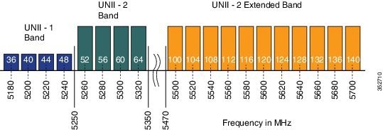
Although the 5 GHz band offers more channels, care should be given in the overall design as the 5 GHz channels have varying power and indoor/outdoor deployment restrictions. For example, in North America, the U-NII-1 can only be used indoors and it has power restriction of 50 mW maximum power, both U-NII-2 and U-NII-2e are subject to Dynamic Frequency Selection.
- By default U-NII-2e channels are disabled in the DCA channel list, check what channels are being used using this command:
WLC5760#show ap dot11 5ghz channel
802.11a 5 GHz Auto-RF Channel List
Allowed Channel List : 36,40,44,48,52,56,60,64,149,153,157,161
Unused Channel List : 100,104,108,112,116,132,136,140,165
WLC5760(config)#ap dot11 5ghz rrm channel dca add <channel>
Available channels in North America and Europe are 100 - 140 (8 additional channels). Channels 120, 124, and 128 are disabled in the US, and severely penalized in ETSI DFS rules and are not supported.
DCA Restart
Once you have made selections for channels and channel widths, or in the case of a new network, completed installing all APs, DCA will manage the channels dynamically and make adjustments as needed over time and changing conditions. However, if this is a new installation, or you have made major changes to DCA such as changing channel widths or adding new APs, then it is advisable to restart the DCA process which initializes an aggressive search mode (startup), and provides an optimized starting channel plan.
In order to determine which WLC is currently the group leader run this command:
WLC5760#show ap dot11 5ghz group
WLC5760#show ap dot11 24ghz group
From the identified group leader re-initialize DCA by running this command:
WLC5760#ap dot11 5ghz rrm dca restart
WLC5760#ap dot11 24ghz rrm dca restart
Verify the restart by running this command:
WLC5760#show ap dot11 5ghz channel
DCA Sensitivity Level : STARTUP (5 dB)
DCA 802.11n/ac Channel Width : 80 MHz
Note![]() Startup mode will run for 100 minutes – reaching a solution generally within 30 - 40 minutes. This can be disruptive to clients (lots of channel changes) if you have made significant changes (channel width, numbers of APs). Do this step last – as changes during the startup change the question you are asking.
Startup mode will run for 100 minutes – reaching a solution generally within 30 - 40 minutes. This can be disruptive to clients (lots of channel changes) if you have made significant changes (channel width, numbers of APs). Do this step last – as changes during the startup change the question you are asking.
WebAuth Best Practices
These are the best practices for Central (CWA) and Local (LWA) WebAuth configurations:
- Release 3.3.3 SE and later are the recommended release for any WebAuth network deployments.
- Configure the virtual-ip under the global parameter-map to drop the unauthenticated HTTPS traffic for the LWA scenario.
- Configure per user max HTTP connections (15) and WebAuth state time out (5 min) for LWA scenario.
This is how to make the changes:
WLC5760(config)#parameter-map type webauth global
WLC5760(config-params-parameter-map)#virtual-ip ipv4 <virtual-ip>
WLC5760(config-params-parameter-map)#timeout init-state sec 300
WLC5760(config-params-parameter-map)#max-http-conns 15
WLC5760(config)#ip access-list extended cwa_redirect_acl
WLC5760(config-ext-nacl)#permit tcp any any eq www
Note![]() For a complete webauth configuration, download the WebAuth Bundle available on cisco.com.
For a complete webauth configuration, download the WebAuth Bundle available on cisco.com.
Security
These are the best practices for security:
WPA2 + 802.1X WLAN
Although the controller and APs support WLAN with SSID using Wi-Fi Protected Access (WPA) and WPA2 simultaneously, it is very common that some wireless client drivers cannot handle complex SSID settings. Whenever possible, we recommend WPA2 only with Advanced Encryption Standard (AES), however due to standards and mandatory Wi-Fi Alliance certification process, TKIP support is required across future software versions. It is a good idea to keep the security policies simple for any SSID such as a separate WLAN/SSID with WPA and Temporal Key Integrity Protocol (TKIP), and a separated one with WPA2 and Advanced Encryption Standard (AES). Since TKIP is being deprecated, it is recommended to use TKIP together with WEP, or migrate out of TKIP completely and use PEAP if possible.
This is how to create a WLAN with WPA2 and 802.1X enabled:
WLC5760(config-wlan)#security wpa
Configure RADIUS authentication server on specified WPA2/802.1X WLAN:
WLC5760(config-wlan)#security dot1x authentication-list method_list_name
Configure RADIUS accounting server on specified WPA2/802.1X WLAN:
WLC5760(config-wlan)#accounting-list <name>
Note![]() For detailed security and AAA configuration, refer to the Security Configuration Guide, Cisco IOS XE Release 3SE (Cisco WLC 5700 Series).
For detailed security and AAA configuration, refer to the Security Configuration Guide, Cisco IOS XE Release 3SE (Cisco WLC 5700 Series).
Identity Design Tip - Use AAA Override
If designing for identity based networking services, where the wireless clients should be separated in several sub-networks for security reasons, such as each one with different security policies, it is a good idea to use one or two WLANs together with the AAA-Override feature. This feature allows you to assign per user settings. For example, move the user to either a specific dynamic interface in a separated VLAN or apply a per user Access Control List (ACL).
WLC5760(config-wlan)#aaa-override
WLC5760#show wlan name <WLAN id>
Max Associated Clients per WLAN : 0
Max Associated Clients per AP per WLAN : 0
Use Faster RADIUS Timeout
It is recommended to have the lowest configured RADIUS timeout as possible for a big or busy network. Since the longer the timeout is defined, the longer a frame re-transmission for the queue for RADIUS is held. Depending on the capacity of the network, and how busy the queue may be, a longer timeout may increase chance of retransmission failure rate. For most network deployment with high authentication count, a smaller timeout is better to improve capacity handling in the controller.
The timeout, retransmission, and encryption key values can be configured globally for all RADIUS servers, on a per-server basis, or in some combination of global and per-server settings.
This is how to configure globally for all radius servers:
WLC5760(config)#radius-server timeout 1 (in sec)
This is how to configure for a specific radius server:
EAP Identity Request Timeout
In the controllers, the default timeout for the EAP Identity request may need to increase for some situations similar to when implementing One Time Passwords (OTP) or Smart Card, where the user interaction is needed in answering the identity request.
WLC5760(config)#wireless security dot1x identity-request timeout <seconds>
TACACS+ Management Timeout
It is best practices to increase the retransmit timeout value for TACACS+ authentication, authorization, and accounting servers if you experience repeated re-authentication attempts or the controller falls back to the backup server when the primary server is active and reachable. This is especially true when implementing for use with One Time Password (OTP).
To configure TACACS+ retransmit timeout globally for all TACACS servers:
WLC5760(config)#tacacs-server timeout 1 <seconds>
To configure TACACS+ retransmit timeout for a specific TACACS Server:
SNMP and Prime Best Practices
Create SNMP Community and Users
By default, the controller does not have an SNMP user or community configured. Keep in mind that your SNMP settings must match between the controller and the Prime Infrastructure (PI). Also, you should use encryption and hash keys that match your security policies.
This is how to configure SNMP community:
WLC5760(config)#snmp-server community TEST ro | rw
This is how to configure SNMP users:
WLC5760(config)#snmp-server user admin IT v3 auth md5 password
SNMP Best Practices for Prime and IOS-XE Controllers
If you have controllers added to Prime and your network consists of more than 250 APs, then it is a best practice to reduce SNMP traffic between the controller and Prime.
The recommendations below are general guidelines for reducing SNMP traffic between Prime and IOS-XE controllers using Background Task settings in Prime. Consider the recommendations carefully based on your network size and needs before taking any action.
To disable or change Background Tasks Interval in Prime, go to the Administration tab and select Background Task under System Settings:
- Disable Mesh Stream Clients and Mesh Link Performance Background tasks because the IOS-XE controllers do not support MESH mode currently.
- Increase Clean Air Background Tasks Interval to 60 minutes.
- If Voice over WLAN is not used in your network, disable Radio Voice Performance and Traffic Stream Metrics Background Tasks.
- If unmanaged APs are not a concern in your network, disable the task.
- Under Wireless Configuration Audit Background Task, uncheck the RRM Audit Box check box, if it is not required.
- Increase the Rogue AP background task interval to 4 hours if Rogue APs are not a concern within the network.
- In Prime version 2.2, under the Radio Performance task details page, select the tasks that apply to your network to be included in the report.
Note![]() It is not recommended to change the timeout and retries values for SNMP Parameters in Prime for WLCs.
It is not recommended to change the timeout and retries values for SNMP Parameters in Prime for WLCs.
It is recommended to periodically monitor CPU utilization and check for spikes in some processes such as snmp_subagent. The following is an example of how to monitor CPU utilization:
Monitor the sorted CPU utilization of the processes to the thread level:
WLC5760#show processes cpu sorted detailed | exclude 0.00
Application Visibility and Control (AVC)
Enabling AVC, the controller can detect more than 1000 applications. AVC enables you to perform real-time analysis and create policies to reduce network congestion, costly network link usage, and infrastructure upgrades.
Application Visibility and Control (AVC) classifies applications using Cisco's Deep Packet Inspection (DPI) techniques with Network-Based Application Recognition (NBAR) engine and provides application-level visibility and control into Wi-Fi network. After recognizing the applications, the AVC feature allows you to either drop or mark the traffic.
The controller has a default AVC flow record and flow monitor called “wireless avc basic”. To check the details of the default flow record and flow monitor, issue this command:
WLC5760#show flow record wireless avc basic
WLC5760#show flow monitor wireless-avc-basic
To enable AVC visibility on a WLAN (e.g. for baseline application utilization):
WLC5760(config-wlan)#ip flow monitor wireless-avc-basic input
WLC5760(config-wlan)#ip flow monitor wireless-avc-basic output
To show AVC statistics on a WLAN (show application utilization per WLAN):
WLC5760#show avc wlan <WLAN id> top 10 application aggregate
Enable High Availability AP SSO
AP Stateful Switchover (AP SSO)
IOS XE 3.3 SE release for Cisco 5700 Series Wireless Controller introduces 1:1 Active-Standby redundancy model for High Availability (HA) with the CT5760 controllers using the StackWise-480 technology. HA in Cisco 5700 Series Wireless Controller is enabled using Cisco StackWise-480 technology. StackWise-480 identifies active and standby members in the stack as per the Cisco IOS Software SSO technology. All the control plane activities are centralized and synchronized between the active and standby units. The Active Controller centrally manages all the control and management communication. The network control data traffic is transparently switched from the standby unit to the active unit for centralized processing. The 12 ports of the CT5760 HA redundant pair can be connected to the infrastructure network either through a single switch or two switches.
Bulk and Incremental configuration is synced between the two controllers at run-time and both controllers share the same IP address on the management interface. The CAPWAP state of the Access Points that are in Run State is also synced from the active WLC to the Hot-Standby WLC allowing the APs to be state-fully switched over when the Active WLC fails. The APs do not go to the Discovery state when Active WLC fails, and Standby WLC takes over as the Active WLC to serve the network.
HA with AP SSO is supported in Cisco 5700 Series Wireless Controllers. IOS XE 3.3 release only supports AP SSO i.e. APs will not disconnect and continue to be associated to the controller after a switchover. However, all clients will be de-authenticated and forced to rejoin the new Active WLC because Client SSO is not supported with this release.
StackWise-480 Connectivity for HA
A CT5760 HA Pair is a special case of a switch stack that can have up to two CT5760 controllers connected through their StackWise-480 ports. The stack members work together as a unified system. A third CT5760 cannot join the switch stack or HA pair. A switch stack always has one active controller and one standby controller. If the active controller becomes unavailable, the standby assumes the role of the active, and continues to the keep the stack operational. The active controller controls the operation of the HA pair, and is the single point of stack-wide management. The term switch is loosely used in the document to refer to the CT5760 WLC for this reason.
StackWise-480 has a stack bandwidth of 480 Gbps and uses SSO to provide resiliency within the HA Pair. The Active CT5760 WLC creates and updates all the wireless information and constantly synchronizes that information with the standby controller. If the active WLC fails, the standby WLC assumes the role of the active WLC and continues to the keep the HA Pair operational. APs continue to remain connected during an active-to-standby switchover.
The StackWise-480 Cable is available in lengths of 50 cm, 1 m, and 3 m.
HA Configuration
There is no need for HA AP SSO configuration. All what you need to do is to connect the Stackwise HA cables between the two 5760 controllers and taking into consideration the best practices for HA pairing process outlined below:
- Adding a powered-on CT5760 WLC (merging) to an existing Active Controller causes both WLCs to reload and elect a new active controller from among themselves.
- Ensure that the controller to be paired is powered down before connecting it to the existing Active Controller by using Stack Cables. Once the Stack Cables are connected, power on the new controller. The newly introduced controller will take up its role as a Hot-Standby controller because an Active Controller already exists.
- Similarly, removing a powered-on WLC causes both WLCs to reload. Power down the controller that needs to be removed before disconnecting the Stack Cables to avoid this.
Once HA cable is connected and both controllers are up, one controller will be elected as Active and the other as Standby. Issue the following command to verify HA pairing:
Switch/Stack Mac Address : 44ad.d902.3500 - Local Mac Address
Mac persistency wait time: Indefinite
Switch# Role Mac Address Priority Version State
----------------------------------------------------------------------
*1 Active 44ad.d902.3500 1 A0 Ready
2 Standby 44ad.d902.3b00 1 A0 Ready
Initiate a manual switchover by entering this command to verify HA AP SSO functionality:
WLC5760#redundancy force-switchover
Run this command only when you require a manual switchover.
Note![]() Refer to the High Availability AP SSO Deployment Guide on cisco.com for more detailed explanation and configuration.
Refer to the High Availability AP SSO Deployment Guide on cisco.com for more detailed explanation and configuration.
Rogue Management
Rogue wireless devices are an ongoing threat to corporate wireless networks. Network owners need to do more than just scan for unknown devices; they must be able to detect, disable, locate, and manage rogue/intruder threats automatically and in real time.
Rogue APs can disrupt wireless LAN operations by hijacking legitimate clients and using plain text or other denial-of-service or man-in-the-middle attacks. That is, a hacker can use a rogue AP to capture sensitive information, such as passwords and user names. The hacker can then transmit a series of clear-to-send (CTS) frames, which mimics an AP informing a particular wireless LAN client adapter to transmit and instructing all others to wait. This scenario results in legitimate clients being unable to access the wireless LAN resources. Thus, wireless LAN service providers have a strong interest in banning rogue APs from the air space.
WLC5760#show wireless wps rogue ap summary
Rogue Location Discovery Protocol : Disabled
Rogue on wire Auto-Contain : Disabled
Rogue using our SSID Auto-Contain : Disabled
Valid client on rogue AP Auto-Contain : Disabled
Rogue Detection Report Interval : 10
Rogue AP minimum transient time : 0
Number of rogue APs detected : 282
MAC Address Classification # APs # Clients Last Heard
--------------------------------------------------------------------------------------
0005.9a3e.8a74 Unclassified 1 0 Tue Apr 29 08:13:16 2014
000d.6721.a410 Unclassified 1 0 Tue Apr 29 08:10:47 2014
000d.6721.a411 Pending 1 0 Tue Apr 29 08:19:46 2014
0011.9303.3c50 Unclassified 1 0 Tue Apr 29 08:22:16 2014
0012.0064.a050 Unclassified 1 0 Tue Apr 29 08:17:16 2014
0013.5f57.ac50 Unclassified 1 0 Tue Apr 29 08:16:46 2014
Rogue Detection
There are good reasons to use rogue detection to minimize security risks, such as in a corporate environment. Note that it is critical to evaluate (or avoid altogether) rogue auto-containment, as there are potential legal issues and liabilities if left to operate automatically.
To verify rogue detection on AP:
WLC5760#show ap config general
=================================================
Country Code : US - United States
Regulatory Domain Allowed by Country : 802.11bg:-A 802.11a:-A
AP Country Code : US - United States
Administrative State : Disabled
Min-RSSI
A rogue with a weak RSSI does not provide any valuable information to the network administrator other than it has been heard. A rogue with a weak RSSI also poses less threat to the wireless network than a rogue with a stronger signal. Too many weak signaled rogues could clutter the Prime Infrastructure GUI, making rogue mitigation difficult. This can be avoided by limiting the minimum RSSI value (Minimum RSSI for Rogue Classification) that the AP needs to report the rogue at.
To configure rogue detection based on minimum RSSI of -70dBm:
Rogue Rules
Create a rogue rule for additional conditions set, for example, rule1:
WLC5760(config)#wireless wps rogue rule rule1 priority 1
WLC5760(config-rule)#classify malicious
WLC5760#show wireless wps rogue rule summary
Priority Rule Name State Type Match Hit Count
------------------------------------------------------------------------
1 rule1 Enabled Malicious Any 0
Up to 6 conditions can be added to a Rogue Rule.
Adding condition-based rules can help to easily detect people spoofing on your network. To configure condition rule based on a managed SSID:
WLC5760(config-rule)#condition infrastructure ssid
Add condition based on specific SSID name:
WLC5760(config-rule)#condition ssid <SSID_name>
Add condition based on minimum RSSI, for example, -70dBm:
WLC5760(config-rule)#condition rssi -70
Add condition based on duration (in seconds) the rogue has been detected, for example, 120 seconds:
WLC5760(config-rule)#condition duration 120
Confirm rogue rule conditions:
Wi-Fi Direct
Wi-Fi Direct allows Wi-Fi devices to make direct connections to one another quickly and conveniently to perform action such as print, sync, and share content. A security concern can arise for the wireless network if the device is connected to both the infrastructure and a Personal Area Network (PAN) at the same time. It is recommended to disallow Wi-Fi direct clients to prevent a security hole.
To disallow Wi-Fi direct clients from associating with the WLAN:
Channels Scanning for Rogues
For a local/Monitor mode AP, there is an option under RRM configuration, which allows the user to choose which channel is scanned for rogues. Depending on the Config, the AP scans all channel/country channel/DCA channels for rogues. The following points are quick explanations on benefits of each:
- For higher security, choose all channel.
- Choose DCA channels for performance because system will scan as least as possible.
- For a balance of performance and security, choose country channel option.
This is an example to configure 5 GHz channel scanning for Rogue Detection for all channels:
WLC5760(config)#ap dot11 5ghz rrm monitor channel-list all
This is an example to configure 2.4 GHz monitor channel scanning in configured country code:
WLC5760(config)#ap dot11 24ghz rrm monitor channel-list country
Transient Rogue Interval
Using the transient interval values, you can control the time interval at which APs should scan for rogues. APs can also filter rogues based on their transient interval values.
This feature has the following advantages:
- Rogue reports from APs to the controller are shorter.
- Transient rogue entries are avoided in the controller.
- Unnecessary memory allocation for transient rogues is avoided.
Configure transient rogue interval of 2 min (120 seconds):
WLC5760(config)#wireless wps rogue detection min-transient-time 120
Enable Adhoc Rogue Detection
Similar to general rogue detection, adhoc rogue detection may be ideal in certain scenarios, such as corporates where security is justifiable. However, in scenarios such as open venues/stadiums, citywide, and public outdoors, it is not of value.
Enable ad hoc rogue detection and reporting by entering this command:
Enable Rogue Clients AAA Validation
A good reason to enable AAA validation for rogue clients is so that the WLC will reliably and continuously check for a client to exist on the AAA server, then marking it either valid or malicious.
Enable Rogue Clients MSE Validation
If there is a Mobility Services Engine (MSE) available and integrated, it can share information in its learned clients database to compliment the WLC in validating whether a client is valid or a threat.
To enable the use of MSE (if available) to check if rogue clients are valid,
 Feedback
Contact Cisco
- Open a Support Case

- (Requires a Cisco Service Contract)